Lei Zhao* | Yinhao Wang
© 2022 IIETA. This article is published by IIETA and is licensed under the CC BY 4.0 license (http://creativecommons.org/licenses/by/4.0/).
OPEN ACCESS
The purpose of this paper is to extract data features and denoise the interference excitation source in vehicle electromagnetic compatibility test. The lifting wavelet packet algorithm inherits the multi-resolution characteristics of the classic (first generation) wavelet transform. The transform is only carried out in the time domain, which can achieve in situ operation. It has the advantages of small space occupation, fast transformation speed, easy inversion, etc. It can use energy conservation criteria to extract characteristic energy to identify the conducted interference sources in the vehicle, and the obtained characteristic spectrum is used as the modulation array of the excitation source of the vehicle numerical simulation. In this paper, the collected interference signals are decomposed into lifting wavelet packets, and then the characteristic energy is extracted to identify the conducted interference sources in the vehicle. Signal to noise ratio (SNR), root mean square error (RMSE) and peak error (PE) are used to verify the consistency between the simulation signal and the original signal. The results show that the lifting wavelet packet algorithm has a strong ability to identify the conducted interference sources in the vehicle.
electromagnetic compatibility, second generation wavelet packet, interference source identification, characteristic energy extraction
The automotive electromagnetic compatibility technology involves many aspects such as the external radiation interference prevention and control technology of the whole vehicle, the prevention and control technology of conduction, coupling and radiation interference inside the vehicle, the anti-interference technology of automotive electronic components, the mutual compatibility technology of various electronic and electrical components, and the EMC technology of the whole vehicle and the environment. Many laboratories have conducted various electromagnetic compatibility tests for the safety and reliability of automobiles, and ECE, ISO, CISPR, etc. are also constantly studying and updating standards [1-4].
Computer simulation analysis of automobile electromagnetic compatibility is the only technology that can find electromagnetic compatibility problems in the development stage of automobile electrical system. At the same time, interference problems can be found in advance through numerical analysis before product finalization, and effective measures can be taken. It can be said that the computer simulation analysis of automotive electromagnetic compatibility is an engineering technology method with high economic benefits. This technology usually provides the basis for scheme modification and protection design in the automotive electronic design stage [5-7].
The engineering practice in recent years shows that wavelet analysis has many advantages in signal denoising. The essence of signal extraction is to find out that the measured signal contains the most relevant component of wavelet basis function [8]. Only by constructing the basis function most similar to the measured signal can the maximum wavelet coefficient be extracted in the wavelet transform process. Zhong et al. [9] uses Bior1.5 wavelet to verify its application effect in signal denoising from simulation analysis, experimental verification and field test. In recent years, the second generation wavelet has introduced splitting, prediction and updating steps, and its unique data in situ computing can effectively reduce the memory requirements. Grewenig et al. [10] applies the second generation wavelet to de-noising of cable partial discharge online monitoring signal, which proves that the second generation wavelet is superior to the first generation wavelet in terms of calculation efficiency and de-noising effect. In addition, the second generation wavelet transform directly constructs wavelets in the time domain, and the execution efficiency is correspondingly improved, which is more suitable for parallel processing [11-15]. In order to improve the signal-to-noise ratio of partial discharge signal and remove the excitation source, lifting wavelet packet decomposition is used to denoise the noisy excitation source.
The paper is organized as follows. In Section 1, the principle and calculation flow of lifting wavelet packet algorithm are introduced in detail. In Section 2, the lifting wavelet packet algorithm is used to denoise the actual interference excitation source in the vehicle electromagnetic compatibility test. Section 3 summarizes the contents of this article.
According to the definition of lifting algorithm and wavelet packet transform, the second generation wavelet packet transform algorithm based on interpolation subdivision wavelet is as follows [16-22].
2.1 Decomposition algorithm
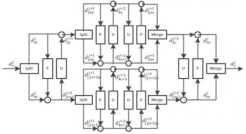
(1) Splitting: splitting the original signal or coefficients at the (j,n), n=1,2,...,2j node into $d_{n o}^j, d_{n e}^j$;
(2) Prediction: calculate the (j+1,2n) node coefficient (i.e., calculate the node coefficient of even nodes) according to Eq. (1):
$d_{2 n}^{j+1}[k]=d_{n o}^j[k]-\sum_{i=1}^N p[i] d_{n e}^j[k+i-N]$ (1)
where, p[i](i=1,2,…,N) is called predictor coefficient.
(3) Update: Calculate the node coefficient of the (j+1,2n) node (i.e. calculate the node coefficient of odd node) according to Eq. (2):
$d_{2 n+1}^{j+1}[k]=d_{n e}^j[k]+\sum_{i=1}^{\tilde{N}} u[i] d_{n e}^{j+1}[k+i-\tilde{N}]$ (2)
where, $u[i](i=1,2, \cdots, \widetilde{N})$ is referred to as the predictor coefficient.
2.2 Reconstruction algorithm
(1) Reverse update: calculate the even coefficient on the (j,n) node from the (j+1,2n), (j+1,2n+1) node coefficient according to Eq. (3):
$d_{n e}^j[k]=d_{2 n+1}^{j+1}[k]+\sum_{i=1}^{\tilde{N}} u[i] d_{2 n}^{j+1}[k+i-\tilde{N}]$ (3)
(2) Reverse prediction: calculate the odd coefficient on the (j,n) node from the coefficient of the (j+1,2n+1) node and the even coefficient on the (j,2n) node according to Eq. (4):
$d_{n o}^j[k]=d_{2 n}^{j+1}[k]+\sum_{i=1}^N p[i] d_{n e}^j[k+i-N]$ (4)
(3) Merge: combine the odd and even coefficients $d_{n o}^j, d_{n e}^j$ to get the coefficients of the (j,2n) node.
The process of the second generation wavelet packet transform is shown in Figure 1.
Figure 1. Generation wavelet packet diagram
2.3 Eigenvalue extraction
The wavelet packet decomposition noise reduction process of the interference excitation source signal is as follows:
(1) The number of decomposition layers is determined, and the original signal is decomposed into full binary tree to obtain the node coefficients of each node;
(2) The entropy function of each wavelet coefficient is calculated by eliminating the selected cost function;
(3) Select the best second generation wavelet packet basis;
(4) The coefficients of each node of the optimal second generation wavelet packet tree are quantized by threshold;
(5) Reconstruct the node coefficients after threshold processing;
(6) Analysis of noise removal effect.
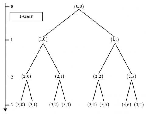
According to the lifting wavelet packet transform principle and interpolation subdivision wavelet construction algorithm, the second generation wavelet constructed above is used for full binary tree decomposition with three decomposition levels, as shown in Figure 2.
Figure 2. Wavelet packet decomposition schematic
2.3.1 Selection of cost function and optimal wavelet packet
The selection of wavelet packet basis directly affects the application effect of lifting wavelet packet transform. At present, the search algorithm of wavelet packet basis mainly adopts the wavelet packet basis selection method based on the minimum entropy standard. This algorithm uses the logarithmic energy entropy as the information cost function En, and defines the logarithmic energy entropy of the wavelet packet coefficients at the (j,n) node as $E=\sum \log \left(d_n^j[k]\right)^2$.
2.3.2 Threshold quantization
Soft threshold method is selected for denoising to retain the local features of the original signal:
$\tilde{d}(k)=\operatorname{sgn}(d(k))\left(|d(k)|-T_j\right)=\left\{\begin{array}{l}0,|d(k)| \leq T_j \\ d(k)-T_j, d(k)>T_j \\ d(k)+T_j, d(k)<T_j\end{array}\right.$ (5)
The thresholds of each scale are determined by the following formula:
$T_j=\frac{\sigma \sqrt{2 \log (N)}}{\log (j+1)}$ (6)
where, Tj is the threshold value corresponding to each decomposition scale, and j is the decomposition scale.
$\sigma=\frac{{median}\left(d_j(k)\right)}{0.6745}$ (7)
The noise variance in the signal is unknown and is estimated by Eq. (7), where median(•) is the median function. According to Eqns. (5)-(7), the wavelet packet coefficients of the optimal wavelet packet decomposition can be threshold quantized.
2.3.3 Analysis of noise removal effect
In order to quantitatively evaluate the signal-to-noise separation effect of the improved wavelet packet optimal basis decomposition algorithm, three evaluation indexes, namely, SNR, RMSE and PE, are adopted:
$S N R=10 \lg \left\{\sum_{n=1}^N s^2(n) / \sum_{n=1}^N[\hat{s}(n)-s(n)]^2\right\}$ (8)
$R M S E=\frac{1}{N} \sum_{n=1}^N[\hat{s}(n)-s(n)]^2$ (9)
$P E=\max _{n=1}^N(\hat{s}(n)-s(n))$ (10)
where, N is the number of sampling points of the signal, s(n) is the original signal, and $\hat{s}(n)$ is the signal after signal noise separation. After the original signal is denoised, the higher the signal-to-noise ratio is, the smaller the root mean square error and the peak error are, which indicates that the better the performance of the algorithm is.
Figure 3. Noise Removal Effect (Diesel ECU)
The measured data is decomposed into 3-layer second-generation wavelet packets, with M=4 and N=4. The denoised signal is obtained by threshold processing and reconstruction of the wavelet packet coefficients corresponding to the optimal second-generation wavelet packet basis. The conducted interference generated by ECU and left headlamp in diesel engine is studied. From the filtered signal of the second generation wavelet packet in the figure, it can be seen that the interference caused by the test system and environmental noise in the measured signal has been basically eliminated.
As shown in Figures 3 and 4, (a) the waveform curve after noise reduction is smoother than the waveform curve of the noisy signal in the figure. The vibration characteristics such as peak rise and decay are more clearly displayed in the vibration signal after noise reduction. The useful information figure objectively reflects the main components of the measured blasting vibration signal. (b) The figure shows the relative error analysis between the reconstructed signal and the measured signal before and after blasting vibration signal de-noising using the second generation wavelet packet. The noise reduction effects are: SNR=34.3046, RMSE=0.8279, PE=2.6798; SNR=33.9380、RMSE=0.4119、PE=1.6776。 It can be seen intuitively that the SNR of the second generation wavelet packet denoising based on SGW (4,4) is higher, the root mean square error (RMSE) is higher, and the peak error (PE) is lower, and the denoising effect is better.
Figure 4. Noise Removal Effect (Left headlamp)
The lifting wavelet packet decomposition based on the optimal basis decomposition is used to decompose the noise components in the vehicle electromagnetic compatibility test data. The logarithmic energy entropy is selected as the cost function, the soft threshold algorithm is used to filter the high-frequency wavelet coefficients, and the mean square error, signal to noise ratio and peak error are used as the evaluation indicators. The results show that the method has a strong ability to identify the main interference sources of the vehicle voltage fluctuations.
[1] Deng, Z.Y. (2005). Analysis of electromagnetic compatibility test technologies. Electric Power Automation Equipment, 25(8): 92-95.
[2] Abramovich, B.N., Kabanov, S.O., Krasavina, M.A., Polishchuk, V.V. (2003). Voltage limiters and electromagnetic compatibility. Russian Electrical Engineering, 74(5): 72-75.
[3] White, R.D., McCormack, L.M., Finlayson, A., Hooper, P.W. (2006). Electrical system integration, electromagnetic compatibility (EMC) interface management of railway electrification systems. HKIE Transactions, 13(1): 55-59. https://doi.org/10.1080/1023697X.2006.10668032
[4] Liang, Z., Xue, Z. (2004). Study on parameter measuring method of coupling transmission lines. Electrotechnical Journal, 196: 47-60.
[5] Cannas, B., Fanni, A., Maradei, F. (2002). Crosstalk prediction in twisted bundles by a neural approach. In 2002 3rd International Symposium on Electromagnetic Compatibility, pp. 638-641. https://doi.org/10.1109/ELMAGC.2002.1177512
[6] Zhao, Z.D. (2005). Wavelet shrinkage denoising by generalized threshold function. In 2005 International Conference on Machine Learning and Cybernetics, 9: 5501-5506. https://doi.org/10.1109/ICMLC.2005.1527916
[7] Buades, A., Coll, B., Morel, J.M. (2008). Nonlocal image and movie denoising. International Journal of Computer Vision, 76(2): 123-139. https://doi.org/10.1007/s11263-007-0052-1
[8] Zhou, R., Bao, W., Li, N., Huang, X., Yu, D. (2010). Mechanical equipment fault diagnosis based on redundant second generation wavelet packet transform. Digital Signal Processing, 20(1): 276-288. https://doi.org/10.1016/j.dsp.2009.04.005
[9] Zhong, H., Yang, C., Zhang, X. (2012). A new weight for nonlocal means denoising using method noise. IEEE Signal Processing Letters, 19(8): 535-538. https://doi.org/10.1109/LSP.2012.2205566
[10] Grewenig, S., Zimmer, S., Weickert, J. (2011). Rotationally invariant similarity measures for nonlocal image denoising. Journal of Visual Communication and Image Representation, 22(2): 117-130. https://doi.org/10.1016/j.jvcir.2010.11.001
[11] Guo, C.E., Zhu, S.C., Wu, Y.N. (2007). Primal sketch: Integrating structure and texture. Computer Vision and Image Understanding, 106(1): 5-19. https://doi.org/10.1016/j.cviu.2005.09.004
[12] Cheng, H.D., Xue, M., Shi, X.J. (2003). Contrast enhancement based on a novel homogeneity measurement. Pattern Recognition, 36(11): 2687-2697. https://doi.org/10.1016/S0031-3203(03)00054-2
[13] Ma, X., Zhou, C., Kemp, I.J. (2002). Interpretation of wavelet analysis and its application in partial discharge detection. IEEE Transactions on Dielectrics and Electrical Insulation, 9(3): 446-457. https://doi.org/10.1109/TDEI.2002.1007709
[14] Zhang, H., Blackburn, T.R., Phung, B.T., Sen, D. (2007). A novel wavelet transform technique for on-line partial discharge measurements. 1. WT de-noising algorithm. IEEE Transactions on Dielectrics and Electrical Insulation, 14(1): 3-14. https://doi.org/10.1109/TDEI.2007.302864
[15] Shim, I., Soraghan, J.J., Siew, W.H. (2000). Digital signal processing applied to the detection of partial discharge: An overview. IEEE Electrical Insulation Magazine, 16(3): 6-12. https://doi.org/10.1109/57.845021
[16] Shim, I., Soraghan, J.J., Siew, W.H. (2000). A noise reduction technique for on-line detection and location of partial discharges in high voltage cable networks. Measurement Science and Technology, 11(12): 1708. https://doi.org/10.1088/0957-0233/11/12/309
[17] Claypoole, R.L., Davis, G.M., Sweldens, W., Baraniuk, R.G. (2003). Nonlinear wavelet transforms for image coding via lifting. IEEE Transactions on Image Processing, 12(12): 1449-1459. https://doi.org/10.1109/TIP.2003.817237
[18] Dabov, K., Foi, A., Katkovnik, V., Egiazarian, K. (2007). Image denoising by sparse 3-D transform-domain collaborative filtering. IEEE Transactions on Image Processing, 16(8): 2080-2095. https://doi.org/10.1109/TIP.2007.901238
[19] Coppola, L., Buso, S., Liu, Q., Boroyevich, D., Bell, A. (2005). Application of Fourier and wavelet transforms to the identification of EMI noise sources in SMPSs. In 2005 International Symposium on Electromagnetic Compatibility, 2005. EMC 2005, 2: 584-589. https://doi.org/10.1109/ISEMC.2005.1513582
[20] Qu, J., Zhang, Z., Wen, J., Guo, T., Luo, X., Sun, C., Li, B. (2014). State recognition of the viscoelastic sandwich structure based on the adaptive redundant second generation wavelet packet transform, permutation entropy and the wavelet support vector machine. Smart Materials and Structures, 23(8): 085004. https://doi.org/10.1088/0964-1726/23/8/085004
[21] Xie, Q.M., Zhang, H.Z., Gao, Y., Cao, H.A., Guo, S.Q., Zhong, M.S., Liu, H.Q. (2015). Research on blasting vibration signal denoising based on lifting scheme. In Applied Mechanics and Materials, 713: 647-650. https://doi.org/10.4028/www.scientific.net/AMM.713-715.647
[22] Xu, X., Chen, T., Wang, S. (2011). Fault feature extraction based on optimal energy using lifting wavelet packet. In International Conference on Information Science and Technology, pp. 548-551. https://doi.org/10.1109/ICIST.2011.5765310