Junfei Han | Hua Li*
© 2021 IIETA. This article is published by IIETA and is licensed under the CC BY 4.0 license (http://creativecommons.org/licenses/by/4.0/).
OPEN ACCESS
The key technologies of self-regulating voltage control for wind farms are studied, and the technical indicators of the AVC main and sub-stations of wind farms in the field of large-scale wind power generation are defined. Wind farm voltage control (AVC) control strategy, developed a wind farm AVC simulation test platform, prepared a wind farm AVC field test and conducted a field test. According to the actual control effect of wind farm AVC, the dynamic response characteristics of wind farm AVC and the reactive power performance of wind farm AVC are evaluated according to relevant technical standards.
voltage control of wind farm (AVC), AVC reactive voltage control strategy, Reactive performance
With the continuous development of wind power in China at present, which the safe and stable operation of power grid has brought great challenges due to the inherent intermittent of wind power. The reactive voltage problem is becoming more and more attention. At present, wind power access power grid is mainly in two problems one is that the wind electric field is lacking in reactive power/voltage control strategy, the voltage fluctuation of the high voltage side bus (network point) of wind farm is too large to meet the voltage assessment requirements of the power grid, The other is that lack of coordination control within the wind power plant, in the case of high fan output, it causes the voltage of the terminal voltage of the fan machine to be limited. According to statistics, the rate of reactive/ voltage power in less wind farms reaches more than 90%. The AVC system plays a crucial role in ensuring reducing the reactive loss and improving the safety and stable operation of the unit, the voltage pass rate of the network node. Inner Mongolia is the most installed provincial power grid in China, and there have been a lot of wind and wind power in the wind power of the wind farm.
This project studied the key technology of self-regulation voltage control in wind electric field, and clarified the AVC main station and sub-station technical index of wind farm group in the area of large-scale wind power generation. By studying the AVC control strategy of wind farm, the AVC simulation test platform of wind farm was developed, and the actual control effect and dynamic response characteristics of wind farm AVC were evaluated.
2.1 The structure of AVC system
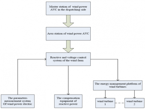
In accordance with the requirements for smart grid scheduling, the automatic voltage control system (AVC) of wind power should have the function of coordinating the reactive power of the wind farm. The bus voltage of the high and low voltage side of the main transformer of the wind farm should be controlled within the scope of dispatching requirements, so that the reactive power supply can run at the optimal power point. Wind farm AVC mode adopts hierarchical hierarchical control mode. The reactive power and voltage of each wind farm are coordinated and controlled through the regional station, and the coordination control between the regional stations is achieved through the scheduling side wind power AVC main station. The voltage control goal of the wind field is to control the voltage value of the public connection point (PCC) in the wind field. The principle is shown in Figure 1 [1-5].
2.2 The principle of SVC device
Static type dynamic reactive power compensation equipments SVC (static var compensator): a parallel connection of static reactive power generator or absorber, based on the inductive or capacitive current adjustment, to maintain or control it with some parameters of the grid connection point (a typical case for control of busbar voltage). SVC includes controlled saturable reactor (SR), thyristor (TSC/TSR), thyristor control reactor (TCR), and mechanical casting reactive power compensation device. The SVC main function indicator is the reactive compensation and harmonic filtering [6-9].
Figure 1. The principle block diagram of wind farm AVC system
3.1 AVC control principle
According to the operation status and reactive power regulation capacity of wind turbine, SVC/SVG and other reactive power regulation equipment, the local reactive power control system of wind farm can be based on the wind power network model, combined with the real-time operation conditions of wind turbine, reactive power compensation device and booster station, and consider various security constraints of power grid and equipment [10, 11]. The optimal control algorithm is used to optimize the calculation and determine the target value of reactive power output of single fan, the reactive power output index of reactive power compensation device, the up / down command of main transformer tap changer, and the implementation of forced draft fan monitoring system, reactive power compensation device and booster station automatic system to complete the automatic voltage regulation function of wind farm [12].
The AVC system, in accordance with requirements of the intelligent power grid scheduling, coordination of wind farm reactive power of the reactive power source, high and low voltage side bus voltage control to wind farms in the scope of scheduling requirements, make each reactive power source to run in the optimal electrical point. Wind farm AVC mode adopts hierarchical hierarchical control mode. The reactive power and voltage of each wind farm are coordinated and controlled through the regional station, and the coordination control between the regional stations is achieved through the scheduling side wind power AVC main station [13].
3.2 Reactive power/voltage control strategy for wind farms
Wind farm reactive power / voltage control is a multi-objective and multi system coordinated optimization control process, which is composed of local wind farm booster station, wind turbine automatic system monitoring system and reactive power compensation equipment. On the premise of system stability and equipment safety, the reactive power of various equipment can be optimized and balanced to meet the requirements of voltage safety control and improve the stability margin of the system. The control procedures and principles are as follows:
(1) through the control of the wind farm reactive power control system for the bus voltage and the voltage of the fan machine, within the wind farm equipment safety under the condition of real-time tracking and meet the requirement and node voltage (grid economic operation requirements) [14];
(2) modeling by wind farms, the comprehensive consideration in the calculation of pressure change, boxes, feeder, fan and other equipment of reactive power demand, real-time computing wind field overall reactive power margin, coordinate with SVC, fan and tap reactive power adjustment ability, keep the wind farm reactive power balance and voltage stability, and keep enough margin to abnormal situation, realize the risk control, realize coordinated control within the wind farm, shrink (wind farm economy operation requirements);
(3) The comprehensive monitoring, state estimation by wind farms, the realization of wind power at the same time to avoid invalid sampled data calculation, the influence of guarantee the overall reliability of the system, avoid the voltage fluctuation causes the fan to take off the net.
The research contents of wind power AVC control strategy mainly include: wind farm reactive power distribution strategy, wind turbine reactive power control and reactive power compensation device (SVC / SVG) control, wind power AVC system operation status analysis and so on [15].
Wind farm integration AVC is a by many the respective systems, this project use of typical centralized monitoring system for wind farm operation of the simulation of RTDS model (including active control and reactive power control), through the establishment of simulation model of wind farm reactive power compensation equipment AVC test platform model of wind farms, the analysis of wind farm AVC control performance. This project studies the interface technology specification of wind farm AVC, and regulates the AVC performance index and interface protocol of different manufacturers.
RTDS at 0-10 v analog output, AVC system required for electric parameters provide wind farms, the AVC system accept analog voltage instruction issued by the main, according to the running situation of the digital model of system voltage (reactive) instructions issued to the fan, SVC, or main transformer.
4.1 Example of simulation model
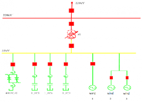
Wind power system model: booster station high side for 220 kv single busbar, low voltage side is 1 period of 35 kv bus bar, a total of 1 on-load voltage regulating transformer, 35 kv bus access 2 sets power lines and a set of reactive power compensation equipments SVC/G, one set of wires connected to the N turbine (equivalent to the fan capacity), another set of wires connected to the two fan, the fan type for doubly-fed induction generator, stand-alone capacity of 1.5 MW, the scope of the power factor of plus or minus 0.95, SVC/G capacity of continuous adjustable, system structure diagram shown in the Figure 2.
TCR parameter as follows: the rated voltage of system is 35 kv, which is the three-phase rated capacity: 38 mvar, which is the trigger Angle range: 110 ~ 165 degrees, phased reactor parameters: 2 x 88.22 mH, wind booster station main transformer: 120 MVA, 13.15%.
Figure 2. Schematic diagram of equivalent system structure of wind farm
4.2 Safety test
When voltage, reactive power and frequency are limited (the limit can be fixed), the pac-4000c wind AVC substation system can automatically block the corresponding reactive power adjustment device or exit the operation when the protective action and switch trip are switched off. The test results are shown in Table 1.
4.3 Field test study
The wind power AVC substation system realizes the reasonable distribution of reactive power among the regulating devices when the external system is stable, the output of the wind farm and the standard voltage of the busbar.
Table 1. Safety test results
|
No |
Inspection items |
Constant value |
The measured values |
|
1 |
The upper limit of wind field bus voltage |
246.4kV |
Wind field bus voltage >246.8 kV block AVC substation |
|
2 |
The lower the voltage threshold of the wind field bus |
235.4kV |
Wind field bus voltage <235 kV block AVC terminal |
|
3 |
The higher the frequency of the system |
50.2Hz |
System frequency >50.3 Hz, block AVC substation |
|
4 |
The lower the frequency of the system |
49.8Hz |
System frequency <49.8 Hz, block AVC sub station |
|
5 |
The upper limit of the fan has no work |
40MVar |
The fan has no work force, >40 MVar, and the corresponding fan has no work adjustment |
|
6 |
The lower limit of the fan |
-40MVar |
The fan has no work force <-40 MVar, and the corresponding fan can be adjusted without work |
|
7 |
SVC upper limit |
180 MVar |
SVC has no work force, >180 MVar, and the closed SVC is adjusted without work |
|
8 |
The lower limit of SVC |
-100 MVar |
SVC has no power output <-100 MVar, and SVC can be adjusted without work |
|
9 |
protect action |
/ |
Protect the action node and close the AVC station |
|
10 |
Main variable high voltage side circuit breaker disconnect |
/ |
The main variable high voltage side circuit breaker is disconnected and the corresponding equipment is locked |
|
11 |
Disconnection of booster station circuit breaker |
/ |
The boost station circuit breaker disconnects and locks AVC sub-station |
Directly from a site cannot test data of single fan or the plant, so choose 356 interval sets electric lines, 356 interval from ten of the fan, total station, a total of 7 of the same set of electrical lines, so the single fan data for one over ten of the 356 interval data, fan factory data for 356 interval of 6.6 times.
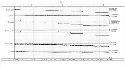
As shown in Figure 3: the wind field has the power to stabilize 50MW, 220 system voltage 222.3 kV, the overall power factor of the wind field is 1, and the AVC command is 222kV.356 power lines are active 6.7 MW, no work 1.7 MVar, power factor hysteresis 0.97; SVC has no work value of 5.2 MVar.
Figure 3. Reactive voltage device control performance
The AVC instruction was changed to 221kV, which was adjusted by AVC four times, and the system voltage was 221.1kv, and the difference of 356 was no work - 1.6mvar, the power factor was 0.97, and the SVC had no power of 10MVar, and the overall power factor of the wind field was 0.958.
The overall adjustment time is 30s, and the order of AVC is adjusted every time. The fan adjusts 500ms, the SVC starts after the adjustment, and the SVC after 18ms is completed. Each adjustment interval is 10s.
Figure 4. Test of reactive power control of wind turbine
Through the above analysis, it can be concluded that the AVC control precision meets the requirements, the fan and SVC control sequence is correct, and the reactive power distribution is reasonable.
As shown in Figure 4. The wind field has a power of 46MW, of which 356 sets of power lines are active 7MW, the pre-initial reactive power 1.6mvar, power factor 0.97, AVC is issued every 10s and no work is -2.9 MVar, and the power factor 0.92.
It can be seen that the power factor of the fan can be adjusted from 0.97 to the entering phase of 0.92. Considering the local box and the line capacitance, the actual power factor range of the fan is 0.95 to 0.95.
The SVC response to reactive voltage automatic control system voltage (reactive power) control command performance is good, and the SVC response time is about 15 milliseconds after the instruction is issued. SVG can meet the reactive voltage automatic control voltage (reactive) control target.
Wind farm AVC system control limit and safety test of security lock and alarm. When one of the following situations occurs, the wind power AVC substation system will automatically block the corresponding reactive power adjustment device or exit the operation, and then recover the regulation after normal.
In this paper, on the basis of a wind farm in Inner Mongolia AVC system digital simulation model is established, and the field experiment was carried out on the AVC system control performance analysis, solve the wind field and node voltage overrun, low reactive response speed for a long time. Results in this paper to improve the performance of the wind farm reactive voltage control system, reduce the wastage of the wind farm in the reactive power source, improving the efficiency of different reactive power source within the wind farm, avoid assessment of power caused by the voltage overrun, provide technical support to improve the wind power generation online, has good social and economic benefits.
[1] Zhao, H.R., Wu, Q.W., Wang, J.H. (2017). Combined active and reactive power control of wind farms based on model predictive control. IEEE Transactions on Energy Conversion, 32(3): 1117-1187. https://doi.org/10.1109/TEC.2017.2654271
[2] Nan, Q., Claus, L.B., Hans, A., Chen, Z. (2017). Multi-stage optimization-based automatic voltage control systems considering wind power forecasting errors. IEEE Transactions on Power Systems, 32(2): 1073-1088. https://doi.org/10.1109/TPWRS.2016.2569448
[3] Shahab, A., Zhu, R.W., Marco, L. (2020). Analysis of voltag control strategies for wind farms. EEE Transactions on Sustainable Energy, 11(2): 1102-1012. https://doi.org/11.1109/TSTE.2019. 2915667
[4] Lin, F.Y., Zhang, C.W., Wang, Y.X. (2021). Emotional deep learning programming controller for automatic voltage control of power systems. IEEE Access, 9: 31880-31891. https://doi.org/10.1109/ACCESS.2021.3060620
[5] Ouyang, J.X., Tang, T., Yao, J. (2019). Active Voltage Control for DFIG-based wind farm integrated power system by coordinating active and reactive powers under wind speed variations. IEEE Transactions on Energy Conversion, 34(3): 1504-1511. https://doi.org/10.1109/TEC.2019.2905673
[6] Liu, X.Y., Wu, G.F., Li, X.W. (2019) Study on voltage stability and control strategy of grid-connected wind farm. IEEE Access, 7: 148843-148852. https://doi.org/10.1109/ACCESS. 2019.2945195
[7] Ma, S.K., Hua, G., Liu, L. (2018). Grid-synchronization stability improvement of large scale wind farm during severe grid fault. IEEE Transactions on Power Systems, 33(1): 216-226. https://doi.org/10.1109/TPWRS.2017.2700050
[8] Ning, Z., Zhao, R., Zhang, B.B. (2021). Closed-loop test for AVC system of wind farm based on real-time simulation. 2021 6th Asia Conference on Power and Electrical Engineering (ACPEE). https://doi.org/10.1109/ACPEE51499.2021.9437079
[9] Yang, W.S., Zhang, B., Liang, L.Q. (2018). Adaptive zone-division AVC method based on reactive power margin evaluation for wind farm. 2018 IEEE International, Conference on Energy Internet (ICEI). https://doi.org/10.1109/ICEI.2018.00023
[10] Han, Y.F., Wang, Y.Q., Yu, C.Y. (2020). Performance evaluation and field test of automatic voltage control system for a wind farm. 2020 IEEE 9th International Power Electronics and Motion Control Conference (IPEMC2020-ECCE Asia). https://doi.org/10.1109/IPEMC-ECCEAsia48364.2020.9368021
[11] Sirine, E., Adel, B., Adel, K. (2019). Integration of automatic voltage regulator and power system stabilizer: Small signal stability in DFIG-based wind farms. Journal of Modern Power Systems and Clean Energy, 7(5): 1115-1128. https://doi.org/10.1007/s40565-019-0539-0
[12] Miao, Y.C., Cheng, H.Z. (2016). An optimal reactive power control strategy for UHVAC/DC hybrid system in east china grid. IEEE Transactions on Smart Grid, 7(1): 392-399. https://doi.org/10.1109/TSG.2014.2377191
[13] Sudipta, G., Younes J.I., Rojan, B. (2020). A dynamic coordination control architecture for reactive power capability enhancement of the DFIG-based wind power generation. IEEE Transactions on Power Systems, 35(4): 3051-3064. https://doi.org/10.1109/TPWRS.2020.2968483
[14] Mohammad, N.I.S., Lasantha, G.M., Manoj, D. (2018). Reactive power management in renewable rich power grids: A review of grid-codes, renewable generators, support devices, control strategies and optimization algorithms. IEEE Access, 6: 41458-41489. https://doi.org/10.1109/ACCESS.2018.2838563
[15] Zhang, X., Chen, Y.L., Wang, Y.X. (2020). Reactive voltage partitioning method for the power grid with comprehensive consideration of wind power fluctuati- on and uncertainty. IEEE Access, 8: 124514-124525. https://doi.org/10.1109/ACCESS.2020.3004484