OPEN ACCESS
Diesel with its high energy density, low fuel consumption, low pollution, is widely used in modern ships and vehicles engine. In this study, an open source software OpenFOAM (Open source Field Operation and Manipulation) was used to simulate the spray characteristics of marine diesel in a rectangular constant chamber. The influence of the computational grid, injection pressure and ambient pressure on the spray character was studied. The research results show in the simulation time period (0-1.6 ms), the grid have high influence on spray penetration, while the Sauter mean diameter (SMD) have little effect. The injection pressure and ambient pressure also have great influence on spray characteristics, the injection pressure increases, the spray penetration distance increases, while SMD decreases. The ambient pressure decreases, spray penetration distance increases, SMD decreases, which is in accordance with the many experimental results.
Marine diesel, Spray character, OpenFOAM, Numerical simulation
In recent years, with the rapid development of China’s economy, China’s ship and vehicle holdings rising year by year. In the present world, the trend of the marine and vehicle powered by diesel is gradually accelerated, and the future diesel demand will become increasingly large. Diesel is the main fuel for the current diesel engine, it is very important for us to study the dynamic process of diesel spray character in the future because it can help us find alternative diesel fuel [7, 8, 12, 13]. Diesel spray characters such as spray penetration distance, spray cone angle, Sauter mean diameter (SMD), spray shape can be very good to judge the quality of fuel atomization performance. In many simulation study, spray penetration and spray cone angle were studied, and compared with experimental data [4, 5]. Sibendu Som et al. [11] studied the effect of fuel evaporation on the spray characters, and compared the results using CONVERGE software and OpenFOAM software. Chen Hu et al. [13] compared the impact of different breakup models TAB model and Wave-KH model on the spray characters, using experimental and CFD method. The results showed Wave-KH breakup model is more suitable than TAB model. Mahdi et al. [7] studied biodiesel spray under ultra-high injection pressure (100MPa, 200MPa and 300MPa) using OpenFOAM, in this study, KH-RT breakup model was used. Most of these researches are not comprehensive, and most of the researches are only study the spray character such as the spray penetration and spray cone angle, but the spray velocity, turbulent kinetic energy and spray volume and so on are not studied.
Over the years, many scholars at home and abroad have carried out a lot of spray simulation and experimental study on diesel [1-5]. Most of the simulation is based on the commercial software such as star-CD, ALV-Fire and FLUENT [4, 8], there is a lot of limitations. In this paper, the numerical simulation of the spray process of the diesel engine is carried out by using the open source fluid dynamics simulation software OpenFOAM. Through numerical simulation, we can easily understand the details of the diesel spray field and spray character, and we can also lay the foundation of finding new alternative fuel.
In recent years, researchers have also used open source software such as OpenFOAM for modeling diesel spray [7, 11]. OpenFOAM is an open source software which takes advantage of its ability to simulate two phase flows using advanced sub-models.
The goal of the current study is study the influence of the computational grid on the spray penetration distance and SMD, and the influence of the injection pressure and ambient pressure on the spray penetration, SMD, spray velocity and turbulent kinetic energy is studied.
2.1 Computational grid
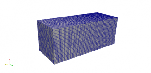
In this simulation, the spray nozzle diameter is 0.85mm, calculation area using rectangular grid (Figure. 1). The rectangle is 20×20×100mm, used two kinds of grid, The computational mesh is a structured hexahedral. One of the grid have a minimum grid 0.4×0.4×1.0mm, its grid number is 250, 000 and another minimum grid is 0.8×0.8×1.0mm, grid number is 62500. The nozzle is located in the center of the top.
Figure 1. The computational grid
2.2 Simulation model
In the simulation, turbulence model is the standard k-epsilon model and the other sub-models such as brokup model, evaporation model as shown in Table 1.These models were selected by many simulation and experiment data, so as to ensure the accuracy of simulation results.
Table 1. The computational models
|
Model type |
Name |
|
Breakup model |
ReitzKHRT |
|
Evaporation model |
Standard Evaporation Model |
|
Heat Transfer model |
RanzMarshall |
|
Drag model |
Standard Drag Model |
|
Injector model |
Hollow Cone Injector |
|
Turbulence model |
k-epsilon |
2.3 Character parameters of marine diesel
Table 2 gives the basic character parameters of marine 0# diesel. The effects of different injection pressure, ambient pressure and different mesh on the spray character were studied by using a single injection of diesel fuel.
Table 2. Character parameters of marine diesel
|
Character parameters |
0#diesel |
|
Density ($kg/{{m}^{3}}$) |
840 |
|
Viscosity ($m{{m}^{3}}/s$) |
3.4 |
|
Flash point (C) |
>60 |
|
Cetane ratio |
>45 |
|
Surface tension (N/m) |
0.0255 |
2.4 Boundary and initial conditions
(1) Orifice flow coefficient
Arcoumauis and Gavaises put forword Orifice flow coefficient formula ${{C}_{d}}$:
${{\text{C}}_{d}}=\frac{Q}{{{A}_{b}}\sqrt{\frac{2({{p}_{s}}-{{p}_{b}})}{{{\rho }_{1}}}}}$ (1)
Where Q denotes Diesel volume flow rate, ${{m}^{3}}/s$, ${{C}_{d}}$ represents Orifice flow coefficient and ${{A}_{b}}$ is Orifice sectional area, $m{{m}^{2}}$, ${{p}_{s}}$ denotes Nozzle chamber pressure, Mpa, ${{\rho }_{1}}$ is diesel density, $kg/{{m}^{3}}$ and ${{p}_{b}}$ is ambient pressure, Mpa.
(2) Cavitation number CN
Arcoumauis and Gavaisesput forword Cavitation number CN formula:
$CN\text{=}\frac{{{p}_{s}}-{{p}_{V}}}{{{p}_{b}}-{{p}_{V}}}$ (2)
Where ${{p}_{s}}$ and ${{p}_{b}}$ is same to formula (2-1), ${{p}_{v}}$ denotes diesel saturated vapor pressure with a default constant ${{p}_{v}}$=1.326Kpa.
(3) Exit speed
Arcoumauis and Gavaises also put forword actual nozzle exit velocity calculation formula:
${{u}_{c}}\text{=(1-}\frac{1}{{{C}_{d}}\times CN}\text{)}\sqrt{\frac{2({{p}_{s}}-{{p}_{b}})}{{{\rho }_{1}}}}$ (3)
Where ${{C}_{d}}$, ${{p}_{s}}$, ${{\rho }_{1}}$ and ${{p}_{b}}$ is the same to formula (2-1), CN denotes Cavitation number, gived by fomula (2-2).
(4) Orifice actual radius
Orifice actual radius is gived:
$r=\sqrt{\frac{Q}{\rho v\pi }}$ (4)
Where Q denotes diesel mass flow rate, kg/s. ρ is diesel density, $kg/{{m}^{3}}$, v is actual nozzle exit velocity, m/s.
(5) Combustion chamber air density
Combustion chamber air density formula is gived by:
$\rho =\frac{PM}{RT}$ (5)
Where P is ambient pressure, Kpa, R denotes ideal air coefficient with a constant R=8.314, M is air molar mass, with a default constant M=29, and T represents absolute temperature, with a constant T=300K.
(6) Initial spray cone angle θ
Guang’an Bo formula:
$\theta \text{=}83.5\frac{L}{D}{{}^{-0.22}}\frac{D}{{{D}_{0}}}{{}^{0.15}}\frac{{{\rho }_{\text{g}}}}{{{\rho }_{1}}}{{}^{0.26}}$ (6)
Where L is Orifice length, mm, D is orifice diameter, mm, ${{D}_{0}}$ denotes orifice inlet diameter, mm, ${{\rho }_{g}}$ is combustion chamber air density, $kg/{{m}^{3}}$. Table 3 is one of calculated spray initial parameters (${{p}_{inj}}=80MPa$, ${{p}_{amb}}=18MPa$, $T=400K$).
Table 3. Diesel spray initial parameters
|
Parameter name |
Parameter values |
|
Orifice flow coefficient |
0.765 |
|
Mass flow rate (kg/s) |
0.14 |
|
Spray cone angle (deg) |
18 |
|
Combustion chamber air density ($kg/{{m}^{3}}$) |
209.29. |
For the simulations the OpenFOAM (Open Field Operation and Manipulation) open-source code has been used. This is an object-orientated code written in C++ in which models can be easily implemented and the code can be readily changed to accommodate special cases and features of interest. Here, a modified version of theOpenFOAM-2.0.x solver dieselFOAM was used. The spray character calculated in this simulation is the spray penetration, Sauter mean diameter and spray velocity.
3.1 The influence of mesh on the marine diesel spray character
As we all know, the size of the grid directly affects the accuracy of the simulation results, this paper will study the impact of grid size on the spray character, and comparison using two kinds of grids (0.4×0.4×1.0 and 0.8×0.8×1.0 mm grid cells).
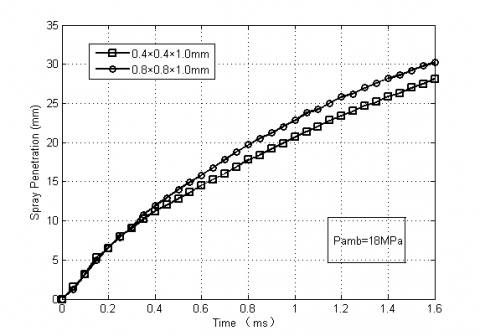
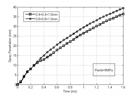
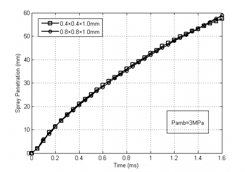
Figure 2, 3, 4 illustrate results of spray penetration obtained with the two different grids .Spray penetration was found to be slightly higher with the coarser grid (0.8×0.8×1.0 mm) in all three cases. In this study, the maximum distance from the injector where the fuel mass fraction is 5% defined as the spray penetration. As can be seen from the graph, the spray penetration distance increases with the increase of the mesh. Because in the cross section of the oil beam the increase of the number of the grid, the gas velocity gradient will increase, and the relative velocity of the liquid droplet decreases.
Figure 2. Comparison of spray penetration obtained with the two grids
Figure 3. Comparison of spray penetration obtained with the two grids
Figure 4. Comparison of spray penetration obtained with the two grids
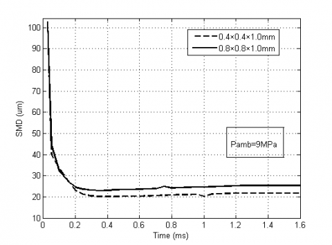
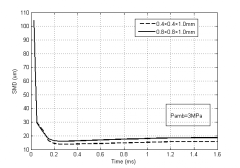
Figure 5. Comparison of SMD obtained with the two grids
Figure 6. Comparison of SMD obtained with the two grids
Figure 7. Comparison of SMD obtained with the two grids
Figure 5, 6, 7 illustrate results of SMD obtained with the two different grids. Can be seen from the picture, with the increase of the grid number, SMD decreases. The main reason is that the mesh number increases, which leads to mesh unit volume smaller, it can reduces the chance of collisions between droplets and reduces the aggregation.
3.2 The influence of injection pressure on marine diesel spray character
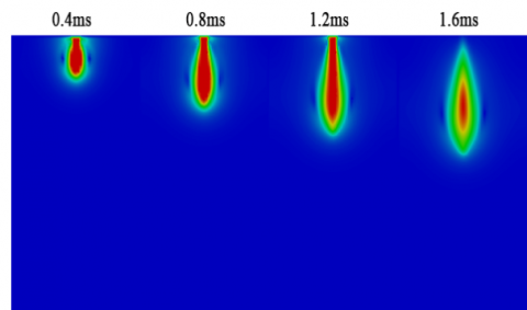
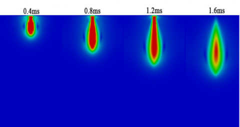
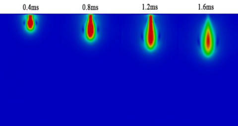
Figure 8, 9 is the spray velosity of 0.4ms, 0.8ms, 1.2ms and 1.6ms when the injection pressure is 80MPa and 120MPa, and the red part is the maximum. As can be seen from the picture, the spray center velocity between 0.4ms and 1.2ms has been increasing (the red area is gradually increasing), the spray center velocity after 1.6ms is gradually reduced (the area of the red area is decreasing). On the other hand, the contrast of the two graphs can be found that the spray velocity of the injection pressure is higher than the injection pressure is low at each time.
Figure 8. Simulated spray velosity 0.4, 0.8, 1.2 and 1.6ms after start of injection, \[{{p}_{inj}}=120MPa,{{p}_{amb}}=9MPa,T=400K\]
Figure 9. Simulated spray velosity 0.4, 0.8, 1.2 and 1.6ms after start of injection, \[{{p}_{inj}}=80MPa,{{p}_{amb}}=9MPa,T=400K\]
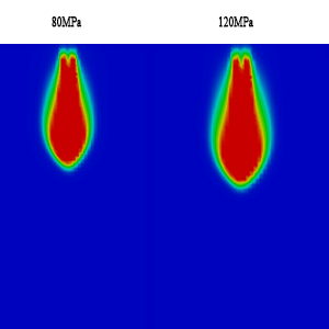
Figure 10. Turbulent kinetic energy at 1.2ms with different injection pressure
Figure 10 is the turbulent kinetic energy at 1.2ms with two different injection pressure. As can be seen, the turbulent kinetic energy when injection pressure is 120MPa is much larger than that of 80MPa.
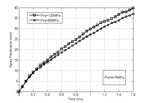
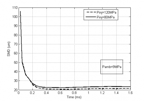
Figure 11, 12 shows the variation curves of spray penetration distance and SMD with time under two different injection pressure. From the picture, we can see that, with the increase of the injection pressure, the spray penetration is increased obviously, but the SMD is reduced, not obviously. Mainly because of the initial velocity of droplets increased, the influence of environmental media on the spray is weakened with the increase of injection pressure.
Figure 11. The influence of injection pressure on marine diesel spray penetration
Figure 12. The influence of injection pressure on marine diesel SMD
3.3 The influence of ambient pressure on marine diesel spray character
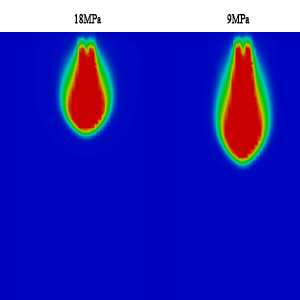
Figure 13, 14 is the spray velosity of 0.4ms, 0.8ms, 1.2ms and 1.6ms when the ambient pressure is 9MPa and 18MPa. We can see from the picture, with the increase of the ambient pressure, the spray center velocity is significantly reduced (red area is obviously smaller).
Figure 15 is the turbulent kinetic energy at 1.2ms with two different ambient pressure. As can be seen from the picture, the greater the ambient pressure, the smaller the turbulent kinetic energy.
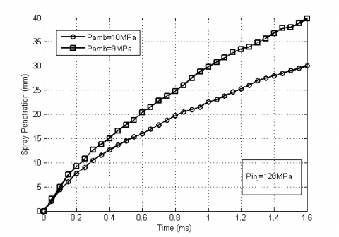
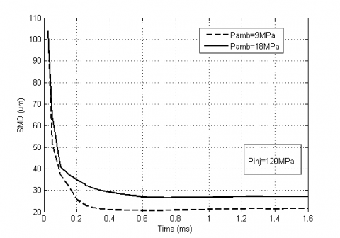
Figure 16, 17 illustrate the spray penetration distance and SMD curve under ambient pressure 9MPa and 18MPa respectively. It can be seen that the increase of ambient pressure, the spray penetration distance decreases, the SMD increases, the main reason is that the influence of the ambient pressure increases, the initial velocity of droplets decreases, so that the penetration distance decreases.
Figure 13. Simulated spray velosity 0.4, 0.8, 1.2 and 1.6ms after start of injection, ${{p}_{inj}}=120MPa,{{p}_{amb}}=9MPa,T=400K$
Figure 14. Simulated spray velosity 0.4, 0.8, 1.2 and 1.6ms after start of injection, ${{p}_{inj}}=120MPa,{{p}_{amb}}=18MPa,T=400K$
Figure 15. Turbulent kinetic energy at 1.2ms with different ambient pressure
Figure 16. The influence of ambient pressure on marine diesel spray penetration
Figure 17. The influence of ambient pressure on marine diesel SMD
(1) In a certain range, the mesh size has a great influence on the spray character of marine diesel. Grid increased, diesel spray penetration increased, Sauter mean diameter decreased.
(2) In a certain range, the impact of the injection pressure on the spray character is very large. Injection pressure rised, the spray penetration increased, Sauter mean diameter decreased, oil beam velocity increased significantly, the spray axis of the diesel oil density increased.
(3) In a certain range, the influence of ambient pressure on the spray character of diesel fuel is also relatively large. Reduced the ambient pressure, spray penetration increased, Sauter mean diameter decreased, nozzle hole center speed increase.
1. Balaji Mohan, Wenming Yang, Kun Lin Tay, Wenbin Yul, Experimental Study of Spray Characteristics of Biodiesel Derived from Waste Cooking Oil, Numer. Energy Conversion and Management, vol. 88, pp. 622-632, 2014.
2. Zhao Xiaowe, Han Xiukong et al., Experimental Study on the Spray Characteristics of Biodiesel, Numer. Internal combustion engine engineering, vol. 29, pp. 17-19, 2008.
3. Wujian, Huayang et al., Simulation and Verification of the Influence of Injection Pressure and Back Pressure on Butanol Diesel Spray, Numer. Journal of Agricultural Engineering, vol. 21, pp. 47-53, 2014.
4. Blaz Vajda, Luka Lešnik, et al., The Numerical Simulation of Biofuels Spray, Numer. Fuel, vol. 144, pp. 71-79, 2015.
5. Mahdi Yousefifard Parviz Ghadimi Mostafa Mirsalim, Numerical Simulation of Biodiesel Spray under Ultra-High Injection Pressure Using OpenFOAM, Numer. The Brazilian Society of Mechanical Sciences and Engineering, vol. 37, pp. 737-746, 2014.
6. Wang Hewu, Zhou Baolong, Study on Spray Characteristics of Two Methyl Ether, Numer. Journal of Xi’an Jiao Tong University, vol. 35, pp. 919-921, 2001.
7. Zhang Xushen, Li Liguang et al., Experimental Study on Spray Characteristics of Bio Diesel Oil, Numer. Journal of Internal Combustion Engine, vol. 25, pp. 173-175, 2007.
8. Y. Gong, O. Kaario, A. Tilli, et al., A Computational Investigation of Hydrotreated Vegetable Oil Sprays Using RANS and a Modified Version of the RNG k - ε Model in OpenFOAM, Numer. SAE International, vol. 1, pp.739-750, 2010.
9. Harun Mohamed Ismail, et al., Application of Adaptive Local Mesh Refinement (ALMR) Approach for the Modeling of Reacting Biodiesel Fuel Spray using OpenFOAM, Numer. SAE International, vol. 1, pp. 2565-2574, 2014.
10. Sibendu Som, et al., Comparison and Standardization of Numerical Approaches for the Prediction of Non-reacting and Reacting Diesel Sprays, Numer. SAE International, vol. 1, pp. 1263-1280, 2012.
11. Jianglei, Hechao et al. Numerical Simulation of Spray Characteristics of Bio Diesel, Numer. Internal Combustion Engine Engineering, vol. 30, pp. 17-21, 2009.
12. Chenchao, Shuai Jinshi et al., The Spray Characteristics of Ethanol, Diesel and Mixed Fuel, Numer. Combustion Science and Technology, vol. 1, pp. 465-469, 2005.
13. Anne Kösters, Anders Karlsson, A Comprehensive Numerical Study of Diesel Fuel Spray Formation with OpenFOAM, Numer. SAE International, vol. 1, pp. 0842-0852, 2011.