Kouidri Mohammed Ali* | Nouar Allal | Djilali Mahi
OPEN ACCESS
Generator protection system is one of the complicated industrial systems incorporating many group elements; measurement transformer, relays, circuit breakers and wiring connectors. Generally, protection systems are described using four characteristics; dependability, Sensitivity, rapidity and selectivity. The stator earth fault is a relatively common type of fault. The generators normally have grounded high impedance, that is to say, a ground via a neutral point resistor. This resistance is normally dimensioned to give a ground fault current of the order of 5 to 15 A in the event of permanent earth fault in high voltage terminals of the alternator. Relatively low ground fault currents cause. The new protection technique, it is called an intermittent defect, this type of defect usually has the following characteristics, A very short earth current pulse of high intensity (up to several hundred amps), lasting less than 1 ms. It occurs / disappears automatically over half a period, possibly over several periods, depending on the state of the power grid and the characteristics of the fault. Over longer periods (from several seconds to several minutes), it can evolve into a permanent fault.
generator protection, intermittent protection, earth faults, stator fault, stator mass fault detection rotor defect, low frequency injection method, neutral point overcurrent protection
Rotating electrical machines, like all industrial devices, can be affected by malfunctions. These defects make them generally unsuited to more or less long term, to ensure their service, and disrupt the operation of other materials. Faults, as well as abnormal operating conditions, must therefore be detected as quickly as possible and cause the electrical disconnection between the machine and the network to which it is connected. The role of alternators electrical protection relays and is to detect, among the various possible defects, those of electrical origin, and to develop the necessary actions of signaling and opening the cut-off device connecting the device to the network. In what follows, the defects are distinguished according to their origin, either internal to the machine concerned, or external. The actions provoked may be of a different nature, aimed either at limiting the damage to the machine or at minimizing the consequences of disturbances on the operation of the machine and the network, or both. After a reminder on the constitution of the machines, electrical defects are described by type of machine, alternators or AC motors. The case of DC motors is not treated here, because this type of motor is largely less used than the AC motor (synchronous or asynchronous) and concerns specific applications [1-3].
In general, a given relay is associated with a type of fault, in analog or digital technique. However, digital techniques today make it possible to group together different measurement, action and monitoring functions in the same equipment, powered by the appropriate measurement reducers. The concepts of personnel safety and dependability are of prime importance in these materials used in complex industrial processes. The stator earth fault is a relatively common type of fault. Alternators normally have high impedance grounding, i.e., grounding via a neutral point resistor.
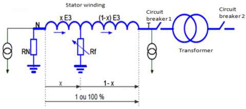
The stator earth fault protection detects earth faults in the stator winding of three-phase machines.
Two cases are to be considered: the direct connection of the machine to the bus bar (direct network connection) or the coupling via a step-up transformer.
When the machine is coupled directly to the bus bar, the stator earth fault also results in the appearance of a ground current.
This principle allows 90% to 95% protection of the stator winding. There will be a very small neutral voltage or a very small residual current if the stator earth fault is located near the neutral of the alternator. The probability for this defect is quite small but not zero.
For small alternators, the risk of not detecting the near-neutral stator ground fault can be accepted. For a large alternator, however, it is often required that these faults be detected. Therefore, a special ground fault protection at the neutral end (100% stator earth fault protection) is required. 100% earth fault protection can be achieved in different ways. [4, 5].
The two main ones are:
- 3rd harmonic voltage detection.
- Injection of neutral point voltage.
Detection of stator mass faults, to detect an earth fault on the windings of an alternator, a neutral point overvoltage relay (59N), a neutral point overvoltage relay (50N), an overvoltage relay can be used. Zero sequence or differential protection against residual currents. Figure 1 represents the protection schemes are simple and have worked well for many years. 100% stator mass protection (low frequency injection method), the 100% stator earth protection using low-frequency injection technology detects faults in the entire winding, including the neutral point of the alternator. If the presence of an earth fault at the neutral point of the alternator or near this point is not detected, the alternator is in fact operating with low earth impedance bypassing the earth by high impedance generally used for large machines. Under these conditions, a second earth fault could cause a very strong current to flow, which could cause serious damage to the machine. This is why 100% stator mass protection is a common requirement on large machines.
Figure 1. Principles of stator earth protection
The low frequency injection technique can be used to provide 100% protection of the stator winding compared to only 20-30% of the winding in the case of the 3d harmonic technique. In addition, the low-frequency injection technique provides protection when the machine is stopped or in service and also during start-up or shutdown phases. The 3d harmonic technique must be blocked or not operational when the machine is stopped or when speeding up and down. In addition, some machines only produce a low level of 3 harmonic voltage (<1% Vn) and for these machines the 3d harmonic method for 100% stator ground protection cannot be used. Thus, for these applications, only the low frequency injection method can provide 100% stator mass protection.
The 100% stator earth protection can be provided by injecting a low frequency alternating voltage at the neutral point or at the machine terminals. Under normal operating conditions, only very low current flows through the capacitance with respect to the stator earth due to the high impedance of this circuit at low frequencies (Xc = 1 / 2πfc).
In the event of an earth fault, the measured current increases due to the lower impedance of the earth fault circuit. The equipment can determine the fault resistance from the injected voltage and the fault current. The protection can also detect earth faults at the terminals of the alternator, including at the level of connected components such as voltage transformers.
The neutral point of the generator is supplied by an external source of alternating voltage at low frequency (20 Hz) whose level corresponds to 1% max. Nominal generator voltage. If an earth fault appears in the neutral point of the generator, the voltage of 20 Hz generates a current through the equivalent fault resistance. The protection device calculates the fault resistance from the injected voltage and the generated current. The described protection principle also detects earth faults at the terminals of the generator and of the connected elements such as for example a voltage transformer.
Method of measurement, the 20 Hz current and voltage vectors are produced from the U stat and I stat measurements shown. The protection performs a complex impedance calculation on the basis of these vectors. This method makes it possible to eliminate the disturbing influence of the capacity of the stator and to obtain a high sensitivity. The accuracy of the measurements is enhanced by the use of voltage and current values averaged over several periods.
A possible RPS contact resistance through the neutral point transformer, grounding or voltage transformer is taken into account in this model. Other sources of error are detected with the angular error. In addition to the determination of the earth resistance, the protection has an earth current step using the r ms value of the current, which allows all frequency components to be taken into account. This level is used as a reserve and covers 80 to 90% of the protection zone. A monitoring function monitors the applied 20 Hz voltage as well as the 20 Hz current. Their analysis enables the detection of a failure of the 20 Hz generator or of the coupling circuit. In this case, the resistance determination is blocked. The earth current step remains active [6-9].
The but to the water of the control of the control of the control of the after incident on the circuit breakers.
Table 1 summarizes the technical characteristics of the alternator studied. Visual inspection of the alternator stator was not possible because the alternator rotor was not removed.
Table 1. Main characteristics of the alternator to study
|
Date of manufacture |
412105 / 1987 |
|
Active power |
101 MW. |
|
Apparent power |
129500 kVA. |
|
Voltage |
11.5 kV ± 7.5 kV. |
|
Current |
6501 A. |
|
Frequency |
50 Hz. |
|
Power factor |
0.8. |
|
Speed |
3000 tr / mn. |
|
Number of poles |
2. |
|
Insulation class |
F. |
2.1 Measurement ohmic resistance of stator windings
- Materials used:
- Digital micrometer,
- Thermohygrometer.
- Result of the test:
- Temperature: 12.6℃.
- Humidity level: 56%.
|
Phase (R) |
Phase (S) |
Phase (T) |
|
0.77 |
0.77 |
0.78 |
2.2 Tests under 2500V
The test consists of the application of a 2.5 kV DC voltage for 10 minutes to check the insulation status of the stator winding. The assessment of the state of the insulation will be done by the following parameters:
- Insulation resistance measured at one (1) minute.
- Dielectric absorption ratio.
- Polarization index.
- Leakage current at 10 minutes.
- Capacity to the mass.
- Resorption ratio.
2.3 Test procedure
After separating the stator windings from the circuit breaker (disconnection of the neutral bar), a DC voltage of 2.5 kV was applied to each phase separately and for the three phases together for 10 minutes.
- Appliances used
- Megger BM 25 (5kV).
- Digital thermohygrometer.
Figure 3 shows the block of Simulation can be defined as the use of a mathematical model to generate a description of the behavior of a physical system (process). Figures 4, 5 and 6 show the main advantage of simulation is to provide a good overview of the real behavior of the system. This overview can be difficult to obtain through experience and intuition alone, especially for complex systems with several interacting variables. As soon as the mathematical model responds to parameter change adjustments as a real process, the simulation can be classified as a convenient method that is cheap and safe for understanding the behavior of the actual process and without intervention on the current process operating.
The prediction of the behavior of a system and the physical and thermodynamic properties of pure bodies or mixtures depends on several parameters. The state equations are established to predict whether the physical and thermodynamic properties are in agreement with the actual values without going through the experiment [10-14].
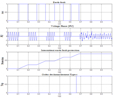
3.1 Intermittent method
Figure 2 represents the intermittent faults (rebooting) are due to weak insulation of the cables or water penetration at the cable connections. After a while, either the faults go out on their own, or they turn into a permanent short circuit. During this period of intermittency, the neutral point resistors of impudent neutral networks may be subject to thermal overload. Standard ground fault protection cannot detect and eliminate with certainty the very short pulses of current that can sometimes occur. The protection calculates the sum of the different individual pulses and triggers after a programmable time.
Figure 2. Trip timing sequence during an electric arc
Figure 3. Simulation module intermittent method
Figure 4. Alternator without faults
Figure 5. Alternator earth faults not allowed with tripping
Figure 6. Alternator earth faults allowed without tripping
Intermittent earth fault protection shall selectively detect intermittent ground faults.
This type of defect usually has the following characteristics:
A very short earth current pulse of high intensity (up to several hundred amperes), lasting less than 1 ms.
It occurs / disappears automatically over half a period, possibly over several periods, depending on the state of the power grid and the characteristics of the fault.
Over longer periods (from several seconds to several minutes), it can evolve into a permanent fault.
3.2 Dielectric absorption test (High voltage)
Table 2 shows the results of the test interpreting the results, leakage currents which are very low during voltage tests which explain that the dielectric strength of the insulation is good.
Table 2. Results of the test
|
|
Phase (R) |
Phase (S) |
Phase (T) |
|
Voltage (kV) |
I (µA) |
I (µA) |
I (µA) |
|
2 |
0.4 |
0.4 |
0.4 |
|
4 |
0.5 |
0.5 |
0.5 |
|
6 |
0.6 |
0.6 |
0.6 |
|
8 |
0.8 |
0.8 |
0.8 |
|
10 |
0.9 |
0.9 |
0.9 |
|
12 |
1 |
1 |
1 |
|
14 |
1.1 |
1.1 |
1.1 |
|
16 |
1.2 |
1.2 |
1.2 |
|
18 |
1.3 |
1.3 |
1.3 |
|
20 |
1.4 |
1.4 |
1.4 |
Table 3. Results of the test (phases S and T guarded)
|
Phase (R) |
|||||
|
U (kV) |
2.06 |
3.04 |
4.05 |
5 |
6.02 |
|
I (mA) |
1793 |
1794 |
1795 |
1796 |
1798 |
|
W (watt) |
152.7 |
157.7 |
166.4 |
178 |
194.6 |
|
Df % |
1.62 |
1.85 |
2.53 |
7 |
9.2 |
|
C (µF) |
0.57 |
0.57 |
0.57 |
0.57 |
0.57 |
Table 4. Results of the test (phases R and T guarded)
|
Phase (S) |
|||||
|
U (kV) |
2.3 |
3.05 |
4.02 |
5.02 |
6.3 |
|
I (mA) |
1791 |
1792 |
1794 |
1795 |
1796 |
|
W(watt) |
148.3 |
152.2 |
160.4 |
175.2 |
193.3 |
|
Df % |
1.44 |
1.85 |
2.02 |
4.94 |
7.66 |
|
C (µF) |
0.57 |
0.57 |
0.57 |
0.57 |
0.57 |
Table 5. Results of the test (phases R and S guarded)
|
Phase (T) |
|||||
|
U (kV) |
2.2 |
3.03 |
4.03 |
5.01 |
6 |
|
I (mA) |
1802 |
183 |
1805 |
1806 |
1807 |
|
W(watt) |
147 |
149.7 |
158.1 |
172.2 |
191.2 |
|
Df % |
1.43 |
1.74 |
1.85 |
3 |
5.2 |
|
C (µF) |
0.57 |
0.57 |
0.57 |
0.57 |
0.57 |
Tables 3, 4 and 5 successively present the data measured for each phase (R, S, T) with all the parameters recorded, including a slight variation in the values of U, I, W and Df except the value of C which remains invariable.
3.3 Loss factor measurement and capacity (C)
Measuring device of Tg (δ). Delta 2000.12 kV.
Ambient temperature: 13℃.
Humidity level: 55%.
Bar Insulation Resistance Measurement (Alternator Output to Group Circuit Breaker).
Table 6 presents the intervals of the criteria of the judgments concerning the parameter IP.
Table 6. Illustrates the criteria of judgments
|
Ip £ 1.5 |
Very weak insulation |
|
1.5 < Ip £ 2.5 |
Wet or polluted insulation |
|
2.5 < Ip £ 4.5 |
Dry and clean insulation |
|
Ip > 4.5 |
Very dry and very clean insulation |
Table 7 shows the values of the bar insulation resistances concerning each phase (R, S, T) at well-determined times.
Table 7. Measurement of insulation resistance of bars
|
|
Applied voltage (5 kV) |
||
|
Time (S) |
Sheath (R) (MΩ) |
Sheath (S) (MΩ) |
Sheath (T) (GΩ) |
|
10 |
2.52 |
6.10 |
149 |
|
15 |
2.54 |
6.2 |
216 |
|
20 |
2.48 |
6.3 |
284 |
|
30 |
2.6 |
6.55 |
320 |
|
45 |
2.48 |
7 |
336 |
|
60 |
2.52 |
6.7 |
346 |
Materials used - PGK 80 high voltage device. It was proceeded to the application of a continuous voltage of 25 kV for 1 minute.
Table 8 shows the results of the dielectric absorption (high voltage) tests on the R and T bars.
Table 8. Dielectric Absorption Test (High Voltage) on R, and T Bars
|
|
Phase (R) |
Phase (S) |
Phase (T) |
|
Voltage (kV) |
I (µA) |
I (µA) |
I (µA) |
|
25 |
0.02 |
0.4 |
0.3 |
Leakage currents are very low during voltage tests. The interpretation of the results is based on the measured and calculated values of the following parameters:
- Resistances of isolations at one minute.
- Dielectric absorption ratio.
- Polarization index.
- Leakage current at 10 minutes.
The insulation resistances measured at ambient temperature are brought back (corrected to the temperature t 20℃ of reference according to the standard C.E.I 34 -18.
The minimum insulation resistance required is given by the following formula:
Ris $(\min )=\frac{U}{\frac{s}{100}}+1000$
U: rated voltage of the alternator in volts: 11500.
S: Apparent power 1295 kVA).
Ris (min) = 5.06 Ω
The dielectric absorption ratio Rad represents the rate of absorption of current by the insulator following application of a DC voltage. It is defined by the following relation:
Rad $=\frac{\text { Ris }(60 s)}{\text { Ris }(30 s)}$
Ris (60 s): Insulation resistance at 60 s.
Ris (30 s): Insulation resistance at 30 s.
The criteria of judgment according to IEEE-STD - 43 are:
Rad < 1.1: Bad insulation.
1.1 £ Rad £ 1.25: Insulation acceptable.
Rad > 1.25: Good insulation.
The polarization index represents the rate of moisture absorption by the insulation. It is defined as the ratio of the insulation resistance measured at 10 minutes to the insulation resistance measured at 1 minute [15-21].
$I p=\frac{R i s(10 m n)}{\text { Ris }(01 m n)}$
An insulating material subjected to a DC voltage, absorbs an induced current of the following form:
$I(t)=C \frac{d v}{d t}+i(t)+I f$
$C \frac{d v}{d t}$ is a current of deplacement.
The displacement current will decrease rapidly and the induced current will be measured as the sum of the absorption current and the leakage current. The leakage current remains constant regardless of the time while the absorption current will gradually decrease over time until reaching almost zero. The leakage current thus remaining is measured after 10 minutes of testing. This current is even lower (of the order of μA) that the insulation is good.
The results of the tests carried out show that the values of these parameters are satisfactory.
In the present work we are interested in the study of the dependability of the protection system of a turbo-alternator.
Simulation for Intermittent Method using Matlab / Simulink software. The simulated model consists of three systems:
The turbine, the synchronous generator, and the network system, a fault has been introduced on a phase to earth. This is a fault on the transmission at 1 sec with a load on the generator.
Simulation without arc fault.
Simulation of an arc fault without triggering.
Simulation of an arc fault with a trigger.
Our study of the protection of the turbo-alternator highlights what differentiates it in the protection of the other elements of the power system. A turbo-alternator is not only the target of short circuits but also abnormal operating conditions whose study of the characteristics of the functions ensuring their detections is sometimes difficult. These defects are not eliminated in the same way; a breaking structure containing three elements is to be controlled according to the defect appearing.
Through the results obtained, we find that:
The insulation state of the entire machine is permissible (dry and clean insulation, polarization index well above 3).
The dielectric strength of the insulation of the three phases of the alternator is good (very low leakage current machine).
However, the alternator output bar (S) to the group circuit breaker has a fault (the bar is perforated), this defect can cause a hot spot.
Recommendation:
• It is recommended to repair the defective part and ensure very strict maintenance.
• It is recommended to repeat the insulation tests before starting the entire chain (circuit breaker - coaxial bars - stator windings…).
• It is recommended to use the methods of artificial intelligence...
|
U |
Applied voltage in (kV) |
|
W |
Power in watts |
|
I |
Current in (mA) |
|
Df |
Loss factor in% |
|
C |
Capacity in (μF) |
|
DC |
Direct current |
|
i (t) |
Absorption current |
|
I f |
Leakage current |
|
U stat |
Offset voltage at protection device |
|
I stat |
Measuring current at the protection device |
|
IP |
Polarization index |
|
Rd |
Dielectric absorption resistance |
|
Ris |
Insulation resistance |
|
Res |
Resorption resistance |
|
Uap |
Applied DC voltage |
|
Rad |
Represents the rate of absorption of current by the insulator |
[1] Kouidri, M.A., Mahi, D., Ferhat, A.Z., Hadjadj, A. (2019). Distribution grid protection. Algerian Large Electrical Network Conference (CAGRE), Algiers, Algeria, pp. 1-6. https://doi.org/10.1109/CAGRE.2019.8713307
[2] Allal, N., Kouidri, M.A. (2019). Simulation study of the evolution of cavity erosion in high voltage electrical cables. Modelling, Measurement and Control A, 92(2-4): 98-109. https://doi.org/10.18280/mmc_a.922-410
[3] Baldwin, M.S., Elmore, W.A., Bonk, J.J. (1980). Improve turbine-generator protection for increased plant reliability. in IEEE Transactions on Power Apparatus and Systems, PAS-99(3): 982-989. https://doi.org/10.1109/TPAS.1980.319728
[4] Power Engineering Society. (2011). IEEE Tutorial on The Protection of Synchronous Generators.
[5] Gustafsson, J., Sandin, F. (2016). District heating monitoring and control systems. Advanced District Heating and Cooling (DHC) Systems Woodhead Publishing Series in Energy, 241-258. https://doi.org/10.1016/B978-1-78242-374-4.00012-4
[6] Mozina, C.J. (1997). Upgrading the protection of industrial-sized generators using digital technology. IAS '96. Conference Record of the 1996 IEEE Industry Applications Conference Thirty-First IAS Annual Meeting, San Diego, CA, USA, 4: 2283-2290. https://doi.org/10.1109/IAS.1996.563892
[7] Koeppl, G., Abaecherli, P., Schmid, A., Voss, G. (2005). Concept and practical testing of single pole operated earthing breakers in an urban cable network CIRED. 18th International Conference on Electricity Distribution, Turin, pp. 1-4. https://doi.org/10.1049/cp:20051154
[8] IEEE C62.92-2 – 1989: IEEE Guide for the Application of Neutral Grounding in Electric Utility Systems, Part Grounding of Synchronous Generator Systems.
[9] CIGRE WG A1.09: Guide for minimizing the damage from stator winding grounds on turbo-generators.
[10] ANSI/IEEE C37.102-1995. Guide for AC Generator Protection.
[11] Elmore, W. (1994). Protective Relaying, Theory and Application. Marcel Dekker.
[12] Electricity of France. Technical notice on plants thermics (fascicle N19) "the alternator", aut1968.
[13] Yazici, B., Kliman, G.B., Premerlani, W.J., Roegl, R.A., Robinson, G.B., Abdel-Malek, A. (1977). An adaptive on-line statistical method for fault detection using stator current. IAS '97. Conference Record of the 1997 IEEE Industry Applications Conference Thirty-Second IAS Annual Meeting, New Orleans, LA, USA, pp. 213-220. https://doi.org/10.1109/IAS.1997.643030
[14] Bonnett, H.A., Soukup, G.C. (1986). Rotor failures in squirrel cage induction motor. IEEE Trans. Industry Applications, IA-22(6): 1165-1173. https://doi.org/10.1109/TIA.1986.4504850
[15] Razik, H. (2002). The spectral content of the current Absorbed by the asynchronous machine in case of failure, state of the art. review 3EI n°29, June 2002.
[16] Kliman, G.B., Premerlani, W.J., Koegl, R.A., Hoeweler, D. (1996). A new approach to on-line fault detection in AC motors. IAS '96. Conference Record of the 1996 IEEE Industry Applications Conference Thirty-First IAS Annual Meeting, San Diego, CA, USA, pp. 687-693. https://doi.org/10.1109/IAS.1996.557113
[17] David, E., Lamarre, L. (2007). Low-frequency dielectric response of epoxy-mica insulated generator bars during multi-stress aging. in IEEE Transactions on Dielectrics and Electrical Insulation, 14(1): 212-226. https://doi.org/10.1109/TDEI.2007.302890
[18] Hao, C., Gao, B. (2016). Study on the frequency domain dielectric spectroscopy of rotating machines insulation. 2016 IEEE International Conference on High Voltage Engineering and Application (ICHVE), Chengdu, 2016, pp. 1-4. https://doi.org/10.1109/ICHVE.2016.7800599
[19] Shokry, A. (2016). Kriging based fault detection and diagnosis approach for nonlinear noisy dynamic processes. Computer Aided Chemical Engineering, 38: 55-60. https://doi.org/10.1016/B978-0-444-63428-3.50014-X
[20] Blodt, M., Granjon, P., Raison, B., Rostaing, G. (2008). Models for bearing damage detection in induction motors using stator current monitoring. IEEE Transactions on Industrial Electronics, 55(4): 1813-1822. https://doi.org/10.1109/TIE.2008.917108
[21] Cheng, S., Habetler, T.G., Mayor, J.R. Harley, R.G. (2013). Generalized bearing roughness fault detection in claw-pole generators. 2013 IEEE Energy Conversion Congress and Exposition, Denver, CO, pp. 4432-4437. https://doi.org/10.1109/ECCE.2013.6647293