T. Yuvaraj | P. Anusha | M. Naga Swapna Sri | R. Thanigaivelan*
© 2023 IIETA. This article is published by IIETA and is licensed under the CC BY 4.0 license (http://creativecommons.org/licenses/by/4.0/).
OPEN ACCESS
Electrochemical micromachining (ECMM) is an important machining process for machining materials susceptible to produce burrs during contact machining process. In this research copper plate of thickness 2mm and tool electrode of 464μm were machined through ECMM process under the sodium nitrate electrolyte (NaNO3).The tool electrode is coated with ceramic material and prevent stray current and chemical attack. The control factors namely, voltage, electrolyte concentration and duty cycle are varied on machining time and overcut. Higher voltage of 12V takes 1 minute to complete the through hole and the use of ceramic coated tool produces good arc on the circumference of the micro-hole and 65% reduction of overcut. The suitable range of electrolyte concentration for reduced machining time is 24 to 26g/lit. As per TOPSIS analysis, 10V, 24g/lit and 65% duty cycle and 11V, 24g/lit and 75% are the best optimal combinations. ANOVA results show that voltage and electrolyte concentration are the most significant factors with 57.73% and 28.83% contribution, respectively.
TOPSIS, ANOVA, voltage, electrolyte concentration, duty cycle, machining time, overcut
Electrochemical micromachining (ECMM) is an unconventional machining process in which the tool electrode is cathode and workpiece is anode, while passing the current the electrochemical reactions occur in the electrolyte attributing for material removal from the workpiece. The micromachining is a technology in which material removal occurs in the range of 1-999μm. The electrochemical micromachining finds application on machining of electronic components, heat sinks, biomedical components and aerospace components. The electrochemical micromachining has various advantages and visible limitations are stray cut. Research on reducing the stray cut is reported by various researchers such as applying epoxy resin, electroplating of nickel and chromium, spin-coating, polytetrafluoroethylene and ceramic coated tools [1-6]. In this research the research the ceramic coated electrode is considered to machine copper plate in sodium nitrate electrolyte. The coating of ceramic materials is a simple and cost-effective process which arrests the stray current to the maximum extent. The use of ceramic coating in tool electrode arrests the stray current effect in ECMM. The presence of stray current in tool electrode affects the circumference area surface quality and enlarges the hole area leading higher overcut. The use ceramic material as a coating improves the hardness of the tool tip, provides good dimensional stability coating, resistance to corrosion and chemical attack and has high melting point. Conventionally the ECMM tools are coated with enamel coating, hot-dip aluminizing, microarc oxidation a silver-plated glass tube electrode and Nickel and Tungsten coating through chemical vapor deposition method [7-9]. Conventional insulation films have poor durability, and the preparation and coating techniques are complex and have limited repeatability. Moreover, the conventional insulation films are not sensitive towards machining of high aspect ratio holes[10-11]. Hence experiments are conducted with control factors namely voltage, electrolyte concentration and duty cycle are varied and effect of these factors on machining time and overcut is studied. Moreover, the best levels are obtained from the preliminary experiments and optimal combinations on output performance are determined using TOPSIS [12-15]. Additional Analysis of variance (ANOVA) is performed to study the effect of significant factor.
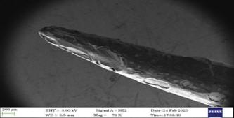
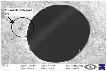
The experiments are performed using the self-built ECMM setup [15]. The setup mainly comprises tool feeding arrangements, electrolyte filter and supply system and electrical supply unit. The electrode of diameter, 464μm and copper plate of thickness 2mm were machined with sodium nitrate(NaNO3) electrolyte. The electrode is insulated with ceramic material and scanning electron microscope image is provided in figure 1. The NaNO3 electrolyte of different range of concentration as presented in table is used in the experiments. The pulsed power supply unit with 0-30V and frequency of 50Hz is kept constant. Experiment pattern follows varying one parameter at a time keeping all factors constant. Figure 2 shows the copper plate with array of micro- holes. The performance of ECMM is measured by machining time and overcut, the machining time denotes the time taken to complete the micro-hole and overcut is calculated by measuring the difference in diameter of micro-hole and electrode diameter. Table 2 presents the machining time and overcut obtained during the machining process. The levels of factors are derived from the table 2 and L9 orthogonal array (Table 3) was formed and most significant factors are identified using ANOVA.
Figure 1. Image showing the tip of electrode with ceramic coating
Table 1. Control factors
|
Control Parameters |
Levels |
||||
|
1 |
2 |
3 |
4 |
5 |
|
|
Voltage in volts |
8 |
9 |
10 |
11 |
12 |
|
Electrolyte centration g/liter |
20 |
22 |
24 |
26 |
28 |
|
Duty Cycle in % |
55 |
65 |
75 |
85 |
95 |
Figure 2. Array of microholes on copper plate
Table 2. Output performance of ECMM
|
S. No |
Voltage (v) |
Electrolyte Concentration (g/liter) |
Duty Cycle |
Machining Time (minutes) |
Overcut (μm) |
|
1 |
8 |
28 |
95 |
4.34 |
388 |
|
2 |
9 |
28 |
95 |
3.32 |
426 |
|
3 |
10 |
28 |
95 |
2.56 |
441 |
|
4 |
11 |
28 |
95 |
1.04 |
448 |
|
5 |
12 |
28 |
95 |
1. 00 |
492 |
|
6 |
12 |
20 |
95 |
17.36 |
378 |
|
7 |
12 |
22 |
95 |
15.42 |
392 |
|
8 |
12 |
24 |
95 |
16.34 |
426 |
|
9 |
12 |
26 |
95 |
12.84 |
446 |
|
10 |
12 |
28 |
95 |
11.80 |
458 |
|
11 |
12 |
28 |
55 |
18.31 |
372 |
|
12 |
12 |
28 |
65 |
14.34 |
411 |
|
13 |
12 |
28 |
75 |
12.45 |
431 |
|
14 |
12 |
28 |
85 |
11.34 |
450 |
|
15 |
12 |
28 |
95 |
9.05 |
462 |
Table 3. L9 OA
|
S. No |
Voltage (v) |
Electrolyte Concentration (g/liter) |
Duty Cycle |
Machining Time (minutes) |
Overcut (μm) |
|
1 |
10 |
24 |
65 |
17.34 |
414 |
|
2 |
10 |
26 |
75 |
13.32 |
426 |
|
3 |
10 |
28 |
85 |
12.56 |
436 |
|
4 |
11 |
24 |
75 |
16.04 |
422 |
|
5 |
11 |
26 |
85 |
13.00 |
432 |
|
6 |
11 |
28 |
65 |
15.36 |
438 |
|
7 |
12 |
24 |
85 |
12.42 |
392 |
|
8 |
12 |
26 |
65 |
10.34 |
436 |
|
9 |
12 |
28 |
85 |
9.84 |
446 |
3.1 Effect of voltage on machining time and overcut
The graph is plotted for voltage on machining time and overcut and shown in figure 3, it is evident that machining time decreases with increase in voltage level. At voltage level of 8V the time taken to machine the micro-hole is 4.34 minutes and it decreases with increase in voltage. At lower voltage level the current density required for electrochemical dissolution is less, hence it takes more time to dissolute the workpiece material. The graphs show that at 11V the machining time is less compared to lower voltage and increase of voltage level to 12 also shows 1 minute to complete the micro-hole. It is obvious that at higher voltage the electrochemical dissolution is faster, attributing for lesser machining. At 12V the presence of accumulated debris and generation of large volume of gas bubbles decelerate the machining process. It can be seen from the graph that for every voltage level the changes are drastic and same is not witnessed between 11 and 12V, hence proper evacuation of debris is required in ECMM process. In case of overcut the lower voltage level shows lower overcut and the curve increases with voltage level. For voltage level of 11-12V the overcut increases drastically. It is due to the fact that the presence of debris attributes for sparking resulting in over etched circumference as shown in figure 4. The application of ceramic coating on the tool reduces the stray current and focus the current density towards the workpiece which witnessed in the figure 5 showing the micro-hole with good arc.
Figure 3. Voltage vs machining time & overcut
Figure 4. Micro-hole with over-etched circumference
Figure 5. Micro hole with good arc
3.2 Effect of electrolyte concentration on machining time and overcut
The effect of electrolyte concentration on machining time and overcut is shown in figure 6. The machining time for lower electrolyte concentration is more and reduces with electrolyte concentration. It is evident from the graph that for electrolyte concentration of 22g/lit it is 15.42 minutes and it slightly increases to 16.34 minutes. Further increase in electrolyte concentration increases the number of ions required for electrochemical process which attributes for reduced machining time. The electrolyte concentration between 24 - 26g/lit shows linear decrease in machining time, hence it is the suitable range of electrolyte concentration for achieving lower machining time. The overcut is found to increase with the electrolyte concentration however the use of ceramic coated tool has reduced the overcut. Normally, overcut in electrochemical micromachining is 3 times the diameter of the tool electrode. In this research the diameter of electrode is 464μm and the diameter of the hole developed at parameter combination of 12V, 28g/lit and 95% duty cycle is 916μm which is 65% reduction compared to literature [10].
Figure 6. Electrolyte concentration vs machining time, overcut
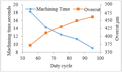
3.3 Effect of duty cycle on machining time and overcut
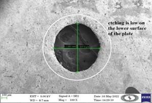
Figure 7 shows the effect of duty cycle on machining time and overcut; it is clear that machining time reduces with the duty cycle. At constant frequency of 50Hz the total time for pulse on and off is calculated as 20miliseconds. The duty cycle is the ratio of pulse on time to total time, and with increase in total time, the pulse on time for machining increases. This attributes for more current density in the machining zone resulting in less machining at higher level of duty cycle. Similarly for overcut, it increases with the duty cycle, the overcut for highest duty cycle is 462μm which is approximately 2 times the electrode diameter. The ceramic coated tool conceals the electrode surface responsible for stray current effect. Moreover the use ceramic coating enhance the hardness of the tool tip, dimensional stability and inert the corrosion and chemical reactions. These properties avoid the delamination of coating due to micro-sparking which occurs due to sporadic short circuiting due to trapping of debris in between inter-electrode gap. In order to understand the stray current effect and flushing of the debris the scanning electron microscope image (figure 8) of the bottom side of the micro hole is taken and it shows less over etched surface on the circumference of the hole. Hence, it is evident that use of ceramic coated tool reduces the overcut by significant percentage.
Figure 7. Duty Cycle Vs Machining time, Overcut
Figure 8. Bottom side view of the micro-hole
TOPSIS is a multi-criteria decision making method the output performance values are normalized and equal weightage are provided for each output performance in table 4 [16-17].
$\mathrm{y}_{i j}=\frac{a_{i j}}{\sqrt{\sum_{i=1}^{i j} a_{i j}^2}}$ (1)
where $i=1,2,3 \ldots \ldots x$ and $j=1,2,3 \ldots y$,
$P_{i j}=y_{i j} \,\,\,w_j$ (2)
where $t=1,2,3 \ldots \ldots x$ and $j=1,2,3 \ldots, y, w_{\mathrm{j}}=$ represents the weight of the $j^{\text {th }}$ criteri,
{P1+, P2+ ......Py+}={(maxiPij \ j $\in$ K), (miniPij\ j $\in$ K' )| i=1,2,3 ......x} (3)
{P1-, P2- ......Py-}={(miniPij \ j $\in$ K), (maxiPij\ j $\in$ K' )\ i=1,2,3 ......x} (4)
where K is the index is set of gain criteria and K' is the index set of machining time and overcut criteria.
$I_i^{-}=\left\{\Sigma_{j=1}^y\left(P_{\mathrm{ij}}-P_j^{+}\right)^2\right\}^{0.3} i=1,2,3 \ldots x$. (5)
$I_i^{-}=\left\{\Sigma_{j=1}^y\left(P_{\mathrm{ij}}\quad P_j^{-}\right)^2\right\}^{0.3}i=1,2,3 \ldots \ldots x$. (6)
$R_i=\frac{z_i}{z_i^{+}+z_i^{-}}\,\,\, i=1,2,3 \ldots \ldots x^0 \leq C_l \leq 1$ (7)
The positive and negative matrix is obtained and preference values are calculated and presented in table 5. The highest preference values are ranked 1 and next highest values are ranked second and third.
Table 4. Normalised values of Machining time and overcut
|
Expt No. |
Normalised Values of |
Weighted Normalised Values of |
||
|
|
Machining Time |
Overcut |
Machining Time |
Overcut |
|
1 |
0.4261 |
0.3231 |
0.2130 |
0.1615 |
|
2 |
0.3273 |
0.3324 |
0.1637 |
0.1662 |
|
3 |
0.3086 |
0.3402 |
0.1543 |
0.1701 |
|
4 |
0.3942 |
0.3293 |
0.1971 |
0.1647 |
|
5 |
0.3195 |
0.3371 |
0.1597 |
0.1686 |
|
6 |
0.3774 |
0.3418 |
0.1887 |
0.1709 |
|
7 |
0.3052 |
0.3059 |
0.1526 |
0.1529 |
|
8 |
0.2541 |
0.3402 |
0.1270 |
0.1701 |
|
9 |
0.2418 |
0.3480 |
0.1209 |
0.1740 |
Table 5. Ranking of experiments
|
Expt No. |
Ideal Separation (I+) |
Non-Ideal Separation (I-) |
Relative Closeness to the Ideal Solution (Ri) |
Rank |
|
1 |
0.0125 |
0.0925 |
0.8811 |
1 |
|
2 |
0.0500 |
0.0448 |
0.4724 |
4 |
|
3 |
0.0589 |
0.0376 |
0.3896 |
6 |
|
4 |
0.0185 |
0.0771 |
0.8063 |
2 |
|
5 |
0.0536 |
0.0418 |
0.4384 |
5 |
|
6 |
0.0245 |
0.0702 |
0.7410 |
3 |
|
7 |
0.0640 |
0.0317 |
0.3312 |
7 |
|
8 |
0.0861 |
0.0182 |
0.1748 |
9 |
|
9 |
0.0921 |
0.0211 |
0.1861 |
8 |
Based on the table 5 the optimal control factors and levels is 10V, 24g/lit and 65% duty cycle which is the first ranked in nine experiments. The next best combination is 11V, 24g/lit and 75% duty cycle. ANOVA is carried out to establish the most significant factors [16]. As per ANOVA table 6 voltage and electrolyte concentration is found be a most significant factors.
Table 6. ANOVA results
|
Control Factors |
Degrees of Freedom |
Sum of Squares |
Mean Square |
F-Value |
% Contribution |
|
Voltage |
2 |
0.3152 |
0.1576 |
0.8660 |
57.73 |
|
Electrolyte conc. |
2 |
0.1574 |
0.0787 |
0.4325 |
28.83 |
|
Duty cycle |
2 |
0.0678 |
0.0339 |
0.1863 |
12.41 |
|
Error |
3 |
0.5460 |
0.1820 |
|
1.03 |
|
Total |
9 |
1.0864 |
0.1207 |
|
100 |
On comparing the experimental results and TOPSIS analysis the following correlations are witnessed.
In experimental results the figure 3 shows the machining time reduces drastically in the voltage range of 10-11V and overcut is found increase linearly for voltage level of 11-12V.Based on the TOPSIS results the first and second ranking voltage levels are 10V and 11V respectively. Moreover the electrolyte concentration of 24g/lit shows significant change in the trends of machining time and overcut. The TOPSIS, first and second ranked parameter combination shows the 24g/lit as a significant level. The duty cycle range of 65-85% is found to be significant for machining time and overcut and TOPSIS analysis shows 65% & 75% as the best level.
The ECMM experiments were conducted using ceramic coated tool by varying the voltage, electrolyte concentration and duty cycle of machining time and overcut. The following conclusions are made:
At 12 voltage level the machining time for completing the through hole is 1 minute and for voltage level of 11-12V the overcut increases drastically. The use of ceramic coated tool produces good arc on the circumference of the micro-hole. At parameter combination of 12V, 28g/lit and 95% duty cycle, the diameter of micro-hole is 916μm which is 65% reduction compared to existing literatures values. The suitable range of electrolyte concentration for achieving lower machining time is 24 to 26g/lit. Machining time reduces with increases in duty cycle, the overcut for highest duty cycle is 462μm which is approximately 2 times the electrode diameter. The bottom side of the micro-hole shows less over-etched surfaces.TOPSIS analysis shows that the factors combinations ie 10V, 24g/lit and 65% duty cycle and 11V, 24g/lit and 75% are the optimal solutions. As per ANOVA, voltage and electrolyte concentration are found be a most significant factors with 57.73% and 28.83% contribution, respectively.
|
ECMM |
Electrochemical micromachining |
|
NaNO3 |
Sodium nitrate electrolyte |
|
ANOVA |
Analysis of Variance |
|
TOPSIS |
Technique for Order Preference by Similarity to Ideal Solution |
|
Greek symbols |
|
|
μm |
micrometre |
[1] Thanigaivelan, R., Arunachalam, R. M., Jerald, J., &Niranjan, T. (2011). Applications of Taguchi technique with fuzzy logic to optimise an electrochemical micromachining process. International Journal of Experimental Design and Process Optimisation, 2(4), 283-298,doi: 10.1504/IJEDPO.2011.043565.
[2] Swain, A. K., Sundaram, M. M., &Rajurkar, K. P. (2012). Use of coated microtools in advanced manufacturing: An exploratory study in electrochemical machining (ECM) context. Journal of Manufacturing Processes, 14(2), 150- 159 doi: 10.1016/j.jmapro.2011.11.005.
[3] Liu, G. H., Li, Y., Chen, X. P., &Lv, S. J. (2009). Research on side-insulation of tool electrode for micro electrochemical machining. In Advanced Materials Research (Vol. 60, pp. 380-387). Trans Tech Publications Ltd, doi:10.4028/www.scientific.net/amr.60-61.380.
[4] Geethapriyan, T., Kalaichelvan, K., &Muthuramalingam, T. (2016). Influence of coated tool electrode on drilling Inconel alloy 718 in Electrochemical micro machining. Procedia CIRP, 46, 127-130, doi:10.1016/j.procir.2016.03.133.
[5] Venugopal, P., Arul, T. G., &Thanigaivelan, R. (2022). Performance optimization of a PTFE-coated electrode in electrochemical micromachining. Ionics, 28(10), 4745- 4753,doi: 10.1007/s11581-022-04686-1.
[6] Soundarrajan, M., &Thanigaivelan, R. (2020). Effect of coated and geometrically modified tools on performance of electrochemical micromachining. Materials and Manufacturing Processes, 35(7), 775-782. doi: 10.1080/10426914.2020.1740252.
[7] Park, B. J., Kim, B. H., & Chu, C. N. (2006). The effects of tool electrode size on characteristics of micro electrochemical machining. CIRP annals, 55(1), 197- 200, doi: 10.1016/S0007-8506(07)60397-7.
[8] Hung, J. C., Liu, Y. R., Tsui, H. P., & Fan, Z. W. (2019). Electrode insulation layer for electrochemical machining fabricated through hot-dip aluminizing and microarc oxidation on a stainless-steel substrate. Surface and Coatings Technology, 378, 124995.doi: 10.1016/j.surfcoat.2019.124995
[9] Liu, G., Tong, H., Li, Y., &Zhong, H. (2021). Novel structure of a sidewall-insulated hollow electrode for micro electrochemical machining. Precision Engineering, 72, 356-369, doi:10.1016/j.precisioneng.2021.05.009
[10] Kozak, J., Rajurkar, K. P., &Makkar, Y. (2004). Study of pulse electrochemical micromachining. Journal of manufacturing processes, 6(1), 7-14,doi: 10.1016/S1526- 6125(04)70055-9
[11] Srivatsan, T.S.; Sudarshan, T.S.; Manigandan, K. (Eds.) Manufacturing Techniques for Materials: Engineering and Engineered; CRC Press: Boca Raton, FL, USA, 2018.
[12] Ganesan, S. K., & Rajasekaran, T. (2021). Optimization of Laser Parameters and Dimple Geometry Using PCA- Coupled GRG. Strojniski Vestnik/Journal of Mechanical Engineering, 67(10),doi: 10.5545/sv-jme.2021.7246
[13] Gunasekaran, K., Pradeep Kumar, G., Thanigaivelan, R., Arunachalam, R., Shanmugam, V. (2021). Optimization of turning parameters of cryogenic soaked AZ91 magnesium alloy using TOPSIS coupled Taguchi technique. Journal of New Materials for Electrochemical Systems, Vol. 24, No. 1, pp. 49-54. doi: 10.14447/jnmes.v24i1.a09
[14] Venugopal,P., Saravanan,K.G.,Thanigaivelan, R.,Performance Analysis of EDM on Grey Cast Iron Using RSM and TOPSIS Method. Applied Engineering Letters, 8(1), 2023: 10-16,doi: 10.18485/aeletters.2023.8.1.2
[15] Rajan, N., Thanigaivelan R.R., Muthurajan, K.G. (2018). Effenct of electrochemical machining process parameters on anisotropic property of metal matrix composites Al7075. Journal of New Materials for Electrochemical Systems, Vol. 21, No. 4, pp. 239-242. https://doi.org/10.14447/jnmes.v21i4.a08
[16] Babu, B., Sabarinathan, C., Dharmalingam, S. (2020). Production of aluminum 6063 metal matrix composite with 12% magnesium oxide and 5% graphite and its machinability studies using micro electrochemical machining. Journal of New Materials for Electrochemical Systems, Vol. 23, No. 2, pp. 94-100. https://doi.org/10.14447/jnmes.v23i2.a06
[17] Mythili.T and Thanigaivelan,R(2020) Optimization of wire EDM process parameters on Al6061/Al2O3 composite and its surface integrity studies, Bulletin of the Polish Academy of Sciences Technical Sciences Vol. 68, no.6, pp. 1403–1412, doi: 10.24425/bpasts.2020.135382.