Dharmasa | Ambikapathy A. | Uma Maheswara Rao M.* | Srinivas Rao G.
© 2023 IIETA. This article is published by IIETA and is licensed under the CC BY 4.0 license (http://creativecommons.org/licenses/by/4.0/).
OPEN ACCESS
Transformer is an efficient asset, which is used mainly to step up-step down voltage levels in a power system and it is necessary to find its performance parameters such as efficiency and voltage regulation. These OC-SC tests are very effective in finding the regulation and efficiency of a transformer at any load (without loading the transformer) under any power factor condition. Previously, OC and SC experiments were conducted to obtain the excitation and core components of 1-phase transformer using more equations. For that in the proposed method, first TWO matrices based equations are developed separately to obtain excitation resistance(R0) and reactance (X0), primary equivalent core resistance (R01) and reactance (X0) for 1-phase transformer these tests. Then combined these TWO matrices based equations are reduced to SINGLE equation, which is sufficient to obtain OC-SC test results. Further, conventional and newly developed equations for OC-SC tests are compared taking experimental data. The proposed, a single equation contains unit matrix (having 0 and 1) of 4*4 order. The reading of OC-SC tests is easily fix to compute parameters like R0 plus X0, (excitation components) R01 plus X01 (core components). The developed Single matrix based equation easy to obtain R0, X0, R01 and X01 in the MATLAB format. Calculation time of students, on these R0, X0, R01 and X01 is compared to previous relations and plotted the efficiency versus % load and power factor versus regulation for 1-phase transformer to validate the result. Overall the single matrix equation based procedure results are very effective for OC-SC tests.
OC-SC tests, 1-phase transformer, core components, winding parameters
Advantages of single-phase transformers are If two and more transformers are connected in parallel the service continuity ensures and the system converts reliable and economical. If more transformers are works in parallel the chance of overburdening of particular transformer reduces. The power supply in a single-phase transformer is through one conductor, while in three-phase transformers, the power supply is through three conductors. A single-phase transformer needs two wires to complete the circuit, while a three-phase transformer needs four wires to complete the circuit. A current carrying electrical power transformer has to withstand various impacts such as: thermal, mechanical, chemical, electrical and electromagnetic during steady state and transient loading conditions. Otherwise it leads to failure due to single or multiple reasons. Then, it is necessary to comprehend the various causes of power transformer failures. A failure occurs, when the withstand strength of one of the above key properties is exceeded by operating stresses on insulating material and as well as conducting (passive parameters) material. An insulating material testing method as per (Zhenyu Wu, 2020) is used for the judgment of winding faults based on the resonant frequency of the HV-transformer. This testing method provides a new opening to evaluate parameter identification on axial movement and Short-Circuit (SC) fault under minimum time consideration. Likewise, the transformer winding construction can be considered as complex-nonlinear network, which is composed of distributed parameters, such as resistance, capacitance, and inductance according to (M. Florkowski, 2018) and (K. Preis, 2018).
In case of students to start up the practical knowledge on indirect tests i.e. Open Circuit(OC)-Short Circuit (OC-SC) tests need to calculate efficiency and regulations of 1-phase transformer. These tests are executed with MATLAB simulation environment under no-load, SC test and load test conditions are achieved by (Hammad, 2020) and however in this method transformer saturation analysis is missing. In case of small capacity of 1-phase transformer the performance parameters such as regulations and efficiencies are evaluated using direct load test as per (Abanihi, 2014), yet this direct load test consumes more power and further more rating leads-to more challenging. In (http://www.ee.uidaho.edu/ee/power/jlaw/COURSES/ECE420/S09/Lab/Lab1.pdf, 2007) an experimental technique is applied to determine the phase equivalent parameters using OC-SC tests for three phase transformer and afterwards computed the regulation and efficiency. However, the method claims that tests gives approximate values.
As per (Teixeira, 2018) to understand influence of harmonics voltage distortion is evaluated by the OC-SC tests for transformer equivalent circuit and losses. In this case, it is able to validate that the harmonic distortions of voltage, which are not able to affect the parameters and its circuit equivalent and losses for 3-phase, 15 kVA transformer. Analysis reported in (Eslami, 2018) for three phase circuits having different types of faults including short circuits in nodes and lines found that for open circuits with falling conductors and having internal faults of transformer, both separately or simultaneously.
As per (Masaya Hiraide, 2017) standards such as International-Electro-Technical-Commission (IEC) and (IEC62271-100) requires that the Transformer-Limited-Fault (TLF) interruption is verified based on test duty T10 with an amplitude factor equals to 1.7 for the Transient-Recovery-Voltage (TRV). In (Masaya Hiraide, 2017) authors were measured Short-Circuit(SC) inductances as parameter of model transformer in two parts first considering an iron core and second by not considering the same. The short-circuit inductance with the iron core research to value equal to negligibly small and equals to one without the iron core. For the TRV frequency region in (Masaya Hiraide, 2017) observed that is the reason for the phenomena of low amplitude factor. Further, the same report reveals that the judgment of incipient may be due reactance and resistance may cause power transformers faults in the early stage is plays an important role like being long-lived, soft-operation, avoiding possible power discussion, and ensuring a good an energy system. In this (Ali Kirkbas, 2020) analyzed that the performance of transformer due to physical faults, wherein the fault types will vary based on the electrical test methods, in continuation the method transformer confirms the validity and reliability aspects. In case of distribution transformer operation and construction, it is observed on the state quantities that influence, and fuzzy binary quantification is performed using the state quantities. The association between the state quantities and the fault is explored by the fuzzy-algorithm, and the key state-variables that make the transformer fault are extracted in the paper (Zhichun Yang, 2020). Forecast of life of transformer, plays a role, a simple program is submitted in (Rajesh Reddy D, 2020) to follow the health condition.
Furthermore, winding parameters the leakage inductance act as a performance parameters of transformer because it determines the voltage drop and the short-circuit currents. There are number of ways given (I. Hernández, 2014) to control the leakage inductance: (a) add spaces between the windings; (b) insert a second core between primary and secondary; (c) leave unwound sectors around the core.
To link to the proposed work, the OC and SC lab test, experimental students can refer to this basic online available, which provides information in the form of spreadsheet for transformer specification as reported (https://electrical-engineering-portal.com/download-center/electrical-software/transformer-losses-calculation, 2021). In recent year (Edwell. T. Mharakurwa, 2022) author done review on life time issues of expectancy of transformer during the operational and performance status in order to minimize failures and operating costs.
Indirect OC-SC tests on single phase transformer is used to decide the efficiency and regulation of a transformer under any loaded condition and for any given value of power factor. To find the outcome of parameters of transformer, OC-SC tests takes time more takes more time to solve set of equations in the labs. However, the testing-technique needs simple equation for both OC-SC tests.
3.1 Modified equation for open circuit test
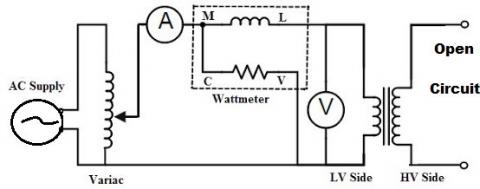
The open circuit test with different meters like voltmeter (V), wattmeter (W), and an ammeter (A) are connected to the transformer as shown in Figure 1.
Figure 1. Open circuit test arrangement for 1-phase transformer
As per Figure 1 in this test, high voltage winding is kept open to discovery the rated output OC voltage, minimum cause for core loss and core loss typical result as tabulated in Table 1 for 2 kVA transformer.
Table 1. Open Circuit Test Readings
|
1-Phase Transformer 230V/115V, 2 kVA |
|||
|
Parameter |
Ioc in A |
Voc in V |
Woc in W |
|
Typical Reading |
0.8 |
115 |
22.5 |
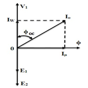
It is known that, Woc = Iron losses and Woc = VoIo cos Øoc (watt-meter reading); cos Øoc = Woc / (Voc Ioc) = no load power factor and once cos Øoc is obtained, then as per phasor diagram of Figure 2 under no-load condition of transformer.
Figure 2. Phasor diagram under no-load condition of 1-phase transformer
Conventional method to find excitation components under OC-SC tests is as follows:
$I_w=I_o \cos \phi_{o c}$ $I_\mu=I_o \sin \phi_c$
$R_0=V_o / I_{\mathrm{w}}$ $X_0=V_o / I_\mu$
where, Iw = working component of the current; Iµ = magnetizing component of the current. To start Voc and Woc need to be known to determine parameters like, X0 and R0 of transformer found in the conventional (in non-matrix form) away. However, to find R0 and X0 arrange relation in matrix form using identity matrix as shown in equation (1).
$\left[\begin{array}{l}R_o \\ X_o\end{array}\right]=\left[\begin{array}{ll}1 & 0 \\ 0 & 1\end{array}\right]\left[\begin{array}{l}V_{o c} / I_w \\ V_{o c} / I_\mu\end{array}\right]=\left[\begin{array}{ll}1 & 0 \\ 0 & 1\end{array}\right]\left[\begin{array}{c}V_{o c} / I_{o c} \cos \phi_{o c} \\ V_{o c} / I_{o c} \sin \phi_{o c}\end{array}\right]$ (1)
Then equation (1) can be further simplified in matrix form Table 1 OC Test readings as below:
$\left[\begin{array}{l}R_o \\ X_o\end{array}\right]=\left[\begin{array}{ll}1 & 0 \\ 0 & 1\end{array}\right]\left[\begin{array}{c}V_{o c}{ }^2 / W_{o c} \\ \mathrm{I}_{o c} \frac{V_{o c}}{\sqrt{\left(\mathrm{I}_{o c} V_{o c}\right)^2-W_{o c}^2}} \\ \mathrm{I}_{o c} V_{o c}\end{array}\right]$ (2)
Furthermore, the equation (2) is simplified to equation (3) in matrix form to find R0 & X0
$\left[\begin{array}{l}R_o \\ X_o\end{array}\right]=\left[\begin{array}{ll}1 & 0 \\ 0 & 1\end{array}\right]\left[\begin{array}{c}V_{o c}^2 / W_{o c} \\ V_{o c}^2 / \sqrt{\left(\mathrm{I}_{o c} V_{o c}\right)^2-W_{o c}^2}\end{array}\right]$ (3)
Now, exciting components R0 and X0 are directly computed using equation (3) of order 2*2 in MATLAB/Calculator and results are given below:
$\left[\begin{array}{c}R_o \\ X_o\end{array}\right]=\left[\begin{array}{ll}1 & 0 \\ 0 & 1\end{array}\right]\left[\begin{array}{c}115^2 / 22.5 \\ 115^2 / \sqrt{\left(0.8^* 115\right)^2-22.5^2}\end{array}\right]$ (4)
$\left[\begin{array}{c}R_O \\ X_O\end{array}\right]=\left[\begin{array}{l}587.77 \\ 148.25\end{array}\right]$ (5)
3.2 Modified equation for short circuit test
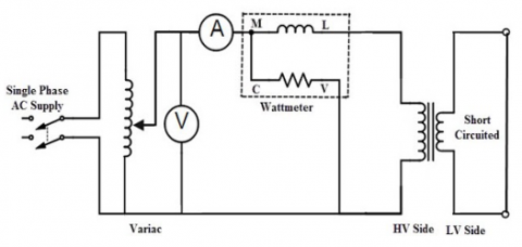
When an experimental set-up is made as per Figure.3, then rated current flowing through the windings of transformer and creates copper loss in it. However, iron losses are neglected due to small amount of voltage is sufficient to drive the secondary short circuited condition. Where Table 2 shows the wattmeter reading as Wsc (full load copper losses) and ammeter reading as Isc and voltmeter reading as Vsc and these values can be used to find primary equivalent resistance R01 and X01.
Table 2. Short circuit (SC) test readings
|
1- Phase Transformer 230V/115V, 2 kVA |
|||
|
Parameter |
Isc in A |
Vsc in V |
Wsc in W |
|
Typical Reading |
8.696 |
15 |
80 |
Figure 3. SC Test arrangement for 1-phase transformer
From SC test readings, the power factor, cos Øoc = VscIsc / Wsc ; R01=Wsc /I2sc and X01 = √(Z01 – R01) and then modified realtions, exlusively for R01 & X01 with k=transmission ratio is expressed in equation (6).
$\left[\begin{array}{l}R_{01} \\ X_{01}\end{array}\right]=\left[\begin{array}{ll}1 & 0 \\ 0 & 1\end{array}\right]\left[\begin{array}{c}R_{0 2} / k^2 \\ \sqrt{\frac{V_{s c}^2}{k^4}-\frac{W_{s c}^2}{k^4 I_{s c}^4}}\end{array}\right]=\left[\begin{array}{ll}1 & 0 \\ 0 & 1\end{array}\right]\left[\begin{array}{l}W_{s c} / k^2 I_{s c}^2 \\ \sqrt{\frac{Z_{02}^2-R_{02}^2}{k^4}}\end{array}\right]$ (6)
Then SC Test related equation (6) can be further re-arranged as:
$\left[\begin{array}{l}R_{01} \\ X_{01}\end{array}\right]=\left[\begin{array}{ll}1 & 0 \\ 0 & 1\end{array}\right]\left[\begin{array}{c}W_{s c} / k^2 I_{s c}^2 \\ \sqrt{\left(I_{s c}{ }^2 V_{s c}{ }^2-W_{s c}{ }^2\right) /\left(k^4 I_{s c}{ }^4\right)}\end{array}\right]$
$\left[\begin{array}{l}R_{01} \\ X_{01}\end{array}\right]=\left[\begin{array}{ll}1 & 0 \\ 0 & 1\end{array}\right]\left[\begin{array}{c}W_{s c} / k^2 I_{s c}^2 \\ \sqrt{\left(I_{s c}{ }^2 V_{s c}{ }^2-W_{s c}{ }^2\right) / k^4 I_{s c}{ }^4}\end{array}\right]$ (7)
Now, equivalent core components R01 and X01 are directly computed using equation (7) in MATLAB/Calculator and results are given below:
$\left[\begin{array}{l}\mathrm{R}_{01} \\ \mathrm{X}_{01}\end{array}\right]=\left[\begin{array}{ll}1 & 0 \\ 0 & 1\end{array}\right]\left[\begin{array}{c}80 / 2^2 * 8.696^2 \\ \sqrt{\left(8.696^2 * 15^2-80^2\right) / 2^4 * 8.696^4}\end{array}\right]$
$\left[\begin{array}{l}R_{01} \\ X_{01}\end{array}\right]=\left[\begin{array}{l}0.264 \\ 0.343\end{array}\right]$
3.3 Single equation for both OC-SC tests
Now, transformer core components (R01 plus X0) and equivalent winding parameters (R01 plus X01) can be directly calculated using equation (8) and OC-SC Tests reading tabulated in Table 1 and Table 2, respectively.
$\left[\begin{array}{l}R_o \\ X_o \\ R_{01} \\ X_{01}\end{array}\right]=\left[\begin{array}{llll}1 & 0 & 0 & 0 \\ 0 & 1 & 0 & 0 \\ 0 & 0 & 1 & 0 \\ 0 & 0 & 0 & 1\end{array}\right]\left[\begin{array}{c}V_{o c}{ }^2 / W_{o c} \\ V_{o c}^2 / \sqrt{\left(\mathrm{I}_{o c} V_{o c}\right)^2-W_{o c}^2} \\ W_{s c} / k^2 I_{s c}^2 \\ \sqrt{\left(I_{s c}{ }^2 V_{s c}{ }^2-W_{s c}^2\right) / k^4 I_{s c}{ }^4}\end{array}\right]$ (8)
Single equation (8) based calculation for parameters of a single-phase transformer in MATLAB.
$\left[\begin{array}{l}R_o \\ X_o \\ R_{01} \\ X_{01}\end{array}\right]=\left[\begin{array}{llll}1 & 0 & 0 & 0 \\ 0 & 1 & 0 & 0 \\ 0 & 0 & 1 & 0 \\ 0 & 0 & 0 & 1\end{array}\right]\left[\begin{array}{c}115^2 / 22.5 \\ 115^2 / \sqrt{(0.8 * 115)^2-22.5^2} \\ 80 / 2^2 * 8.696^2 \\ \sqrt{\left(8.696^2 * 15^2-80^2\right) / 2^4 * 8.696^4}\end{array}\right]=\left[\begin{array}{c}587.77 \\ 148.25 \\ 0.264 \\ 0.343\end{array}\right]$
The proposed calculation of R0 , X0, R01 and X01 single equation (8) is made simple to determine the Efficiency ($\eta$) and Regulation (R) for 1-phase transformer. Table 3 shows approximate time taken by students, who conduct experiment and do calculations to find excitation and core components for 1-phase under OC-SC tests.
Table 3. Calculation time of students to find excitation and core components under OC-SC tests
|
Method to find R0 , X0, R01 and X01 |
Calculation time using CALCULATOR |
Calculation time using MATLAB |
|
Conventional : Non matrix form equations in Section 3.1 |
300 sec |
100 sec |
|
Matrix Equation of 2*2 order Equation (3) in Section 3.1 & Equation (7) in Section 3.2 |
80 sec
|
40 sec |
|
Single Matrix Equation 4*4 Equation (8) in Section 3.3 |
N/A |
20 sec |
The general equation (9) for efficiency is presented as follows:
$\eta=\frac{\text { Power outputin } k W}{\text { Power output in } k W+\text { Losses }\left(W_{o c}+W_{s c}\right)} \times 100$ (9)
If the kVA rating of the transformer is "S", is a fraction of the load "X". Then output power is expressed in kW as S X $\cos \varphi$. Assume that the iron loss at full load is Woc and the copper loss at full load is Wsc (since x =1), Then copper loss at X per unit loading = X2 Wsc. To determine efficiency ($\eta$) & regulation (%R) of the transformer use equation (10) & (11) derived from found by OC and SC tests.
$\eta=\frac{S X \cos \phi}{S X \cos \phi+\left(W_{o c}+W_{s c}\right)} \times 100$ (10)
$\% R=\frac{I_1 R_{01} \cos \phi \pm I_1 X_{01} \sin \varphi}{E_1} \times 100$ (11)
Then, from the SC test data obtain the regulation for 2kVA a transformer results are tabulated in Table 3. To calculate the primary current (I1) of transformer = 2 kVA, I1 = Rating of the Transformer/Primary Voltage (E1) = 2000/115=17.39A. Here, in equation (11) the positive sign for lagging power factor and negative sign for leading power factor for different power factors. The performance parameter as % regulation versus power factors of transformer is seen in Table 4.
Table 4. Calculation of % regulation versus power factors
|
Calculation for % Regulation (R) |
Power factor |
|
$\frac{(17.39 \times 0.264 \times 0.6)+(17.39 \times 0.434 \times 0.8)}{115} \times 100=7.64 \%$ |
0.6 lagging |
|
$\frac{(17.39 \times 0.264 \times 0.8)+(17.39 \times 0.434 \times 0.6)}{115} \times 100=7.13 \%$ |
0.8 lagging |
|
$\frac{(17.39 \times 0.264 \times 1)+(17.39 \times 0.434 \times 0)}{115} \times 100=3.99 \%$ |
Unity |
|
$\frac{(17.39 \times 0.264 \times 0.8)-(17.39 \times 0.434 \times 0.6)}{115} \times 100=-0.74 \%$ |
0.8 leading |
|
$\frac{(17.39 \times 0.264 \times 0.6)-(17.39 \times 0.434 \times 0.8)}{115} \times 100=-2.85 \%$ |
0.6 leading |
Then calculation of efficiencies for a single phase 2 kVA transformer at 0.8 power factor are tabulated in Table 5.
Table 5. Calculation of efficiency versus % load
|
Calculation for % Efficiency ($\eta$) |
Power factor |
|
$\frac{(17.39 \times 0.264 \times 0.6)+(17.39 \times 0.434 \times 0.8)}{115} \times 100=7.64 \%$ |
0.6 lagging |
|
$\frac{(17.39 \times 0.264 \times 0.8)+(17.39 \times 0.434 \times 0.6)}{115} \times 100=7.13 \%$ |
0.8 lagging |
|
$\frac{(17.39 \times 0.264 \times 1)+(17.39 \times 0.434 \times 0)}{115} \times 100=3.99 \%$ |
Unity |
|
$\frac{(17.39 \times 0.264 \times 0.8)-(17.39 \times 0.434 \times 0.6)}{115} \times 100=-0.74 \%$ |
0.8 leading |
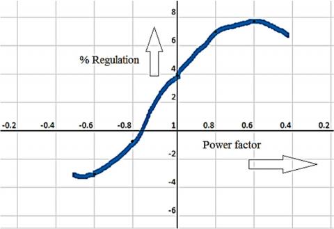
Figure 4. Power factor Vs Regulation of 1-ϕ transformer
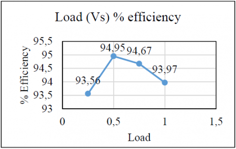
Figure 5. Percentage load Vs efficiency of 1-ϕ transformer
Power factor versus Regulation of Figure. 4 confirms the characteristics of 1-phase transformer based on calculated values taken from Table 4. Parentage load versus efficiency of Figure. 5 confirms the characteristics 1-phase transformer based on calculated values taken from Table 5. From Figure. 4 and Figure. 5, it is observed that the proposed matrix single matrix equation (8) easy to find excitation parameters and core components (R0 ,X0, R01 and X01), then the Table 3 supports the reduction of calculation time for any given single phase transformer. MATLAB based single matrix equation (8) saves overall time of an experiment. It is also found that equation (3) and equation (4) handled separately OC-SC parameter calculation, respectively.
This paper concludes that requirement of an experimental knowledge on 1-phase transformer is an important to study power system. Literature review is done on various performance parameters such as efficiency and voltage regulation for phase transformer and its life expectancy. Here, single equation in matrix form is found suitable to determine the both excitation and core components (R0 ,X0, R01 and X01) for any given 1-phase transformer under Open Circuit (OC) and Short Circuit (SC) tests. To understand easy, first matrix based equations are separately developed for OC & SC tests and then combined into single matrix. These proposed equations will take less time using matrix operation in MATLAB/scientific calculator, when compared to conventional relations to obtain performance parameters, while conducting experiment in laboratory. Usually, in lab after the conduction of OC-SC experiments, students use more equations to determine the equivalent parameters such as resistance and reactance of the 1-phase transformer. Proposed 4*4 matrix based single equation with unity matrix is sufficient to compute both excitation and core components. Finally, matrix based single matrix found efficient and also supports to save at-least 50% of calculation time to fins excitation and core components 1-phase transformer using OC-SC readings. Further, validation of results reported by plotting relation between efficiency versus % load and power factor versus regulation for 1-phase transformer results.
[1] Abanihi, K. V. (2014). Analysis of load test, transformation, turns ratio, efficiency and voltage regulation of single phase transformer. International Journal of Science, Environment and Technology, Vol. 3, No 5,, 1657 – 1667. Doi: www.ijset.net/journal/404.pdf
[2] Ali Kirkbas, A. D. (2020). (Fault diagnosis of oil- immersed power transformers using common vector approach. Electric Power Systems Research, vol 184. https://doi.org/10.1016/j.epsr.2020.106346
[3] Eslami, A. (2018). A three-phase comprehensive methodology to analyze short circuits, open circuits and internal faults of transformers based on the compensation theorem. International Journal of Electrical Power & Energy Systems, Vol 96, 238-252. https://doi.org/10.1016/j.ijepes.2017.09.039
[4] Fault diagnosis of oil-immersed power transformers using common vector approach, vol184. (2020). Electric Power Systems Research. http://dx.doi.org/10.1016/j.epsr.2020.106346
[5] Hammad, A. N. (2020). Experimental simulation analysis for single phase transformer tests. Bulletin of Electrical Engineering and Informatics,Vol. 9, No. 3,. https://doi.org/10.11591/eei.v9i3.1710
[6] http://www.ee.uidaho.edu/ee/power/jlaw/COURSES/ ECE420/S09/Lab/Lab1.pdf. (2007). Retrieved july 21, 2021, from www.ee.uidaho.edu: http://www.ee.uidaho.edu/ee/power/jlaw/COURSES/E CE420/S09/Lab/Lab1.pdf
[7] https://electrical-engineering-portal.com/download- center/electrical-software/transformer-losses- calculation. (2021, July 21). Retrieved July 21, 2021, from https://electrical-engineering-portal.com.
[8] I. Hernández, F. d. (2014). Leakage Inductance Design of Toroidal Transformers by Sector Winding. IEEE Transactions on Power Delivery, Vol. 26, No. 4, 473- 480. http://dx.doi.org/10.1109/TPEL.2013.2251429
[9] M. Florkowski, J. F. (2018). Comparisonof transformer winding responses to standard lightning impulses and operational overvoltages. IEEE Trans. Dielectr. Electr. Insul., vol. 25, no. 3, 965-974. http://dx.doi.org/10.1109/TDEI.2018.007001
[10] Masaya Hiraide, T. K. (2017). High frequency short- circuit inductance for model transformer. Journal of International Council on Electrical Engineering, 102- 110. http://dx.doi.org/10.1080/22348972.2017.1324268
[11] Rajesh Reddy D, R. H. (2020). Residual Life Assessment of Power Transformer. Journal of Research in Science, Technology, Engineering and Management, Vol. 6, No.1, 36-40. http://dx.doi.org/10.17148/IJIREEICE.2020.8617
[12] Teixeira, V. A. (2018). "The influence of harmonic voltage distortion on power transformer equivalent circuit and losses," doi: 10.1109/SBSE.2018.8395786. Simposio Brasileiro de Sistemas Eletricos (SBSE) (pp. 1-6). IEEE. http://dx.doi.org/10.1109/ICSGTEIS.2016.7885761
[13] Zhenyu Wu, L. Z. (2020). A New Testing Method for the Diagnosis of Winding Faults in Transformer, . IEEE Transactions on Instrumentation and Measurement,Vol. 69, No.11, 9203-9214. http://dx.doi.org/10.1109/TIM.2020.2998877
[14] Edwell. T. M.(2022). In-Service Power Transformer Life Time Prospects: Review and Prospects, Hindawi, Journal of Electrical and Computer Engineering, Article ID 9519032, https://doi.org/10.1155/2022/9519032