Gyadari Balram* | P. Satish Kumar
© 2023 IIETA. This article is published by IIETA and is licensed under the CC BY 4.0 license (http://creativecommons.org/licenses/by/4.0/).
OPEN ACCESS
Microgrids of varying sizes and applications are regarded as a key feature of modernizing the power system. With modern technologies, sources of renewable energy are paving the way in microgrid power systems through various converter topologies. However, distortion is caused by harmonics in an electrical system for which many strategies aimed to reduce harmonics in the power system, but they failed to detect harmonics induced by high impedance defects. Also, the occurrence of distortion in power and current discrepancy leads to stability issues of the converter. Hence this research addresses these problems through a novel Harmonic Response Technique using a Packet wavelet transform based high impedance fault diagnosis which determines the distorted current waveforms leading to harmonic energy levels. Furthermore, to minimize the fault current distortion, a Feedback controlled fault current limiting Converter is employed which regulates the system by utilizing a shunt active power filter in a fault current limiter. Moreover, power discrepancy in transition is balanced by accepting a novel Balanced Phase Transition Technique which determines the energy consumption over the current demand period using reactive power & a load factor of the converter using triangular functions which ensure a balanced load phase angle and helps in a smooth transition between phases. Thus the adopted techniques are simulated in the Simulink platform and the consequences depicted a good level of effectiveness in response, balance, and control of the suggested system.
microgrids, sources of renewable energy, harmonics, high impedance, fault current
Electricity can be produced, transferred, and stored more simply, effectively, and affordably as technology advances in the energy area [1]. To efficiently manage power generation and supply in the new liberalized environment of smart cities, it is critical to understand and anticipate the effect of environmental factors on energy demand [2]. As a result of environmental issues and global warming, there is a need to protect the environment by reducing air pollution and considering electricity constraints and energy supply for urban, remote, and rural areas [3] by adopting renewable energy sources. Renewable Energy Resources (RESs) can provide safe, environmentally beneficial, and cost-effective solutions made possible by limitless resources [4] through which the electrical power generating industry has entered a new phase of development that is marked by increased weather variability, a shift away from a hydrocarbon-based economy, and successful energy deployment [5]. Regardless, because of the fluctuating nature of the resources used by RES, the move to clean energy is not without its hurdles, particularly in smaller energy systems such as microgrids, which are more vulnerable to network power fluctuations [6].
Microgrids are small-scale (from 100 kilowatts to multiple megawatts) power networks that are distinct from the major big energy transmission systems, sometimes interconnected, and sometimes wholly disconnected due to geographic limits [7]. The microgrid concept is gaining traction, not only in small islands and remote communities but also in modular configurations within large grids, allowing different districts and facilities to be independent of one another in the event of a network outage and to work independently with greater resilience [8]. Regulation and power administration are the two most critical features of a microgrid. The first is to maintain DC bus voltage, and the second is to keep input sources and loads in power balance [9]. In the microgrid system, power fluctuations occur when a PV source is reliant on the environment linked to a microgrid through various devices and equipments[10]. Renewable energy sources' unpredictable production diminishes the source's dependability and hence to reduce output swings, energy storage methods must be deployed. An efficient converter that functions as a hybrid energy system is mostly utilized to integrate several sources of renewable energy [11] with an effective battery storage system that can compensate for the erratic nature of diverse energy sources [12,13] as energy storage systems help to sustain continuous power generation by meeting load demand. However, there exists variation in power regulation in the grid due to the installation of numerous equipment and hence new strategies for preserving microgrid stability are needed as the usage of resources of renewable energy develops[14].
In addition, other recent review studies focused on different aspects of the Hybrid Renewable Energy Resources (HRES) design process, such as power control methods, software tools employed, and optimization methodologies. Sizing HRES is a tough optimization task because of the competing cost and reliability objectives as demand, electrical generation, and the resources concentrated, on the other hand, are all unpredictable [15]. As a result, establishing a strategy to address challenges in power generation and power systems utilizing sources of renewable energy becomes necessary and the main contributions of the paper include,
Thus by adopting the above mentioned techniques improves the efficiency in terms of response and control of the microgrid system with balanced phase transition.
The structure of the paper has been developed as follows out of which section 1 is the introduction; Section 2 presents the recent works of literature; section 3 depicts the detailed description of the materials and processing methods involved; section 4 deliberates the experimental results and finally, section 5 discusses the conclusion.
Sidorov et al. [16] used sophisticated approaches based on deep reinforcement learning and integral equations to present dynamical models of an AC/DC hybrid isolated power system consisting of four power grids with sustainable generating units & energy storage systems. First, the wind & solar irradiance potential, as well as the electric load as a function of climatic circumstances, are investigated at numerous locations around Lake Baikal's shores. In online mode, the appropriate selection of energy storage system components is supported. Retrospective meteorological datasets are used to justify the method. With such a formulation, several useful recommendations for the optimal management of multiple autonomous AC/DC hybrid power systems with various architectures, equipment compositions, and AC/DC types are produced. Further work must focus on the additional power management, including the issuance of both the internal storage charge and the external network.
Phan et al. [17] focused on the enhancement of HRES with the arrangement of battery and hydrogen FCs. The energy management system, appropriate size, and MPPT (maximum power point tracking) control were all taken into consideration (EMS). New difficulties and possibilities for HRES development have arisen as an output of recent breakthroughs and successes in the disciplines of ML (machine learning) and reinforcement learning (RL). For the case study on an island in the Philippines, the optimal scale of the hybrid sustainable hydrogen energy system was determined using the Hybrid optimization model for multiple energy resources (HOMER) program. Based on the evaluation of HRES EMS and MPPT control, it can be determined that RL is among the most popular rapidly evolving optimum control systems. Finally, for a photovoltaic (PV) system, a hybrid perturbation and observation (P&O) and Q-learning (h-POQL) MPPT was developed. However, for energy management, the system must be developed a multi-agent-based HRES, and the suggested system must be deployed on an isolated micro-grid.
Jha et al. [18] in their article addressed with the support of sophisticated micro-source controllers, the problem of voltage variability in stand-alone microgrids may be addressed. The BES system's high energy density is used to compensate for voltage fluctuations. The movement of electrical energy from the BES system is controlled by a control mechanism. The work is expanded to examine the mechanism of DSM (demand-side management) with the addition of voltage-droop characteristics, and the control design of a DC–AC microgrid integrated with a BES system is provided. The BES system is interconnected to keep the voltage within a safe range, and the proposed work is intended to demonstrate an introduction concept in DSM achieved by voltage reduction on the consumer side. Future work is necessary for the stability study of the suggested control strategy for stand-alone microgrid integrated with the BES unit.
Elnozahy et al. [19] SMC (Sliding mode control) & artificial neural network approaches are used to construct and compare two current controllers. PV (Photovoltaic), battery storage systems, wind turbines, and transmission lines connected to infinite bus bars through a step-up transformer are all included in the HRESs. Both voltage control and current regulation are used by the designed inverter controllers. A DC-DC boost converter is employed to set up a voltage demand at the PCC (point of common coupling). Then, the formulation of an HRES with the established controllers is granted. The developed controllers are considered to operate under various solar radiations, temperatures, and wind speed loading conditions. To test the efficacy of the developed controllers, HRESs with the created controllers are simulated using MATLAB/Simulink. However, further work will require the use of the created adaptive SMC and sophisticated ANN controller.
Soundarya et al. [20] proposed it can eliminate several power conversions by designing & modeling a hybrid DC/AC MG with the real usage of RERs. The maximum power point tracking method uses the interval type 2 fuzzy logic technique to collect solar energy using photovoltaic (PV) panels. Wind and tidal energy are used in the design of the AC grid. The wind turbine is a permanent magnet synchronous generator. Various control systems are familiar with obtaining the most power out of the wind and tidal waves under various situations. These produced energies are connected to the utility grid and can supply the load. These are carried out using the MATLAB/SIMULINK program. The mitigation of power quality issues that arise owing to the critical and sensitive hospital load and compensation of reactive power is measured as the future work.
For [16] the surplus power management, including the issuance of both the internal storage charge and the external network it must be done, for [17], the system has to be implemented on multi-agent-based HRES for energy management and it is needed to develop the proposed system on an isolated micro-grid, [18] requires the constancy analysis of the suggested control approach for stand-alone microgrid integrated with BES unit, [19] utilizing the developed adaptive SMC and the advanced ANN controller are necessitated for future works, [20] the mitigation of power quality issues that arises due to the critical and sensitive hospital load and compensation of reactive power must be looked into. Hence to overcome all the above-mentioned issues a novel technique has to be implemented.
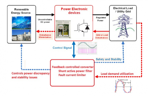
Sources of renewable energy are becoming an increasingly essential aspect in meeting energy demand. The integration of large-scale renewable energy (RE) sources, specifically wind and solar energy, into the grid introduces current and voltage harmonics caused by power electronics devices and inverters connected to the RE sources. Various strategies aimed to reduce harmonics in the power system, but they failed to detect harmonics induced by high impedance defects. Furthermore, converters with fault-tolerant capacity are utilized to limit current fault in the system, ensuring system security but causing inertial and synchronization concerns. When transitioning from grid-linked to islanded mode and before transitioning micro grid feeding electricity to a utility grid, the issue of power disparity emerges; nevertheless, earlier solutions were unable to offer protection when imbalanced loads were present.
Initially, a novel Harmonic Response Technique based on a high impedance fault analysis which employs error detection from the transient and steady-state conditions of the distributive system's voltage & current signals, as well as a variant of the system's load phase angle response due to distorted current waveforms utilizing Packet wavelet transforms leading to harmonic energy levels in arcing current to analyze signals in time-frequency space and reduce noise.
Figure 1. The architecture of the suggested model
Furthermore, to limit the system’s fault current, converters with buck features with fault-tolerant capacity are employed to assure system security, however, this generates inertial and synchronization concerns, requiring the converter output to be changed when the load demand varies and as a result, feedback-controlled fault current limiter is used. To minimize power and fault current in the grid, a converter is used that manages a feedback-controlled buck-boost converter via control signals using a shunt active power filter to compensate current harmonics of nonlinear loads to perform reactive power compensation and to balance the imbalance currents with a fault current limiter. Moreover, if a multiplicative input is present, the performance problem is changed into a stability concern, and the error is minimized by producing a feedback loop that lowers fault current distortion. The issue of power discrepancy in transition is resolved by incorporating a novel Balanced Phase Transition Technique that determines energy consumption over the current demand period using nominal peak load conditions and compares power demand to the target value using load factor & reactive power of the converter using triangular functions. If the extreme demand exceeds the forecast, loads are shut off, preventing overload. Furthermore, the transition between grid and island modes during system loading is addressed by using a synchronous inverter in the system, which ensures a balanced load phase angle and aids in the seamless transition between phases by utilizing triangular functions. The architecture of the suggested system is displayed in figure 1.
3.1 Harmonic response technique
Harmonic response denotes the difference of frequency in a system when subjective to loading. Normally the power system output is delivered in two stages i.e. the transient state result and the steady-state output. High impedance faults are difficult to identify in power system analysis. In our system, the photovoltaic energy source is chosen as the input source for which the response when a load is applied is identified using Packet wavelet transforms to recognize the transient reply. This technique applies voltage & current signals supplied by voltage and current sources, respectively. The recognition process is executed through signal decomposition and threshold of the wavelet packet transform coefficients with comparison to the difference of harmonic waves between transient and steady-state conditions. To estimate the performance of the suggested method in the case of steady- state harmonic distortion, the test signal used was the harmonic distribution without load and to estimate the performance of the suggested method in the case of nonstationary harmonic distortion, the consideration of different test signals proposed by the resource for renewable energy was taken into consideration.
Initially, the current & voltage signals of the system are identified from the Photovoltaic source for which the output is DC. The variables are identified from the packet wavelet model and they denote the voltage & current signals which are the system’s input. The error detection is identified using comparison with the steady and transient state of the system concerning the variants of load phase angle response from the output of the model.
The succeeding equations are extended forms for the measurements which consist of $\mathrm{I}_{\mathrm{rms}}$ and $\mathrm{V}_{\mathrm{rms}}$ and power (P) [22]. The following are the parameters' definitions,
$I_{r m s}=\sqrt{\frac{1}{T} \int_0^T i_t^2 d T}$ (1)
$V_{r m s}=\sqrt{\frac{1}{T} \int_0^T v_t^2 d T}$ (2)
$P=\frac{1}{T} \int_0^T i_t v_t d T$ (3)
where, $v_t$ and $i_t$ is respectively the voltage waveforms and analog current during the observation time $\mathrm{T}$, which is periodic.
The analog waveforms are digitized in practice. Here, $i_n$ and $v_n$ are the digitized waveforms of $i_t$ and $v_t$ respectively, with $\mathrm{n}=0,1 \ldots, 2\mathrm{~N}-1$ ( $\mathrm{N}$ is an integer).
Further, the rms values of voltage & current are simplified using the below-mentioned equations
$I_{r m s}=\sqrt{\frac{1}{2^N} \sum_{n=0}^{2^N-1} i_n^2}=\sqrt{\frac{1}{2^N} \sum_{i=0}^{2^{N-j}-1} \sum_{k=0}^{2^j-1}\left(d_{j, k}^i\right)^2}$ (4)
$V_{r m s}=\sqrt{\frac{1}{2^N} \sum_{n=0}^{2^N-1} v_n^2}=\sqrt{\frac{1}{2^N} \sum_{i=0}^{2^{N-j}-1} \sum_{k=0}^{2^j-1}\left(d *_{j, k}^i\right)^2}$ (5)
where, $\mathrm{d}^{i}_{\mathrm{j}, \mathrm{k}}$, and $\mathrm{d}^{*i}_{\mathrm{j}, \mathrm{k}}$ are wavelet coefficients of $\mathrm{i}_{\mathrm{n}}$ and $\mathrm{v}_{\mathrm{n}}$, respectively of voltage $\&$ current for the frequency band at node $\mathrm{i}$ and level $\mathrm{j}$.
In the wavelet domain, power is calculated by multiplying the wavelet coefficients of current by the wavelet coefficients of voltage for each node at the same level.
$P=\sqrt{\frac{1}{2^N} \sum_{i=0}^{2^{N-j}-1} \sum_{k=0}^{2^j-1} d_{j, k}^i d *_{j, k}^i}$ (6)
where, P is the power of frequency band at node i and level j.
Values of current, power & voltage for utility are determined and the same is identified for the demand side. Thus by utilizing the wavelet packet transform, the error detection based on frequency variation is identified. The detected error is then made null by controlling the input which is done by the converter which is as explained in the next section.
3.2 Feedback controlled fault current limitingconverter
The rise in fault current in a system’s network is owing to the increase in the number of DG units, increase in electrical energy consumption, etc. The magnitude of the fault current should be in a manner that is not exceeding the maximum threshold value. The Fault current limiters (FCL) which are normally inserted in sequence with the circuits play a significant role in limiting the current within the permissible range. Also, FCL can rise power quality, reliability, and transient stability. The fault current should be limited to the maximum possible system limit equipment ratings. The dc reactor current is always kept below a predesigned value based on the transient stability of the system. The current limiter is highly effective in repeated fault conditions.
Hence here to mitigate the fault current in the system, a feedback controller converter-based mitigation is employed which uses a shunt active filter in the circuit. Normally switching losses are present in any converter. As an outcome, in addition to the true power of the load, the utility must provide a little overhead for capacitor leakage and converter switching losses. Hence, the total peak current provided by the source,
$I_{s p}=I_{s m}+I_{m L}$ (7)
where, $I_{s p}$ is the desired source current
$\mathrm{I}_{\mathrm{sm}}$ is the real power
and $I_{m L}$ is the loss component
If the active filter provides the total reactive and harmonic power, then $i_s(t)$ will be in phase with the voltage supplied by the utility and pure sinusoidal and the active filter must give the succeeding compensation current at this time which is,
$i_c(t)=i_L(t)-i_s(t)$ (8)
where, $i_c$ is the instantaneous value of filter current
$\mathrm{i}_{\mathrm{L}}$ is the instantaneous value of load
$i_s$ is the instantaneous value of the source
Hence, the fundamental component of load current is evaluated as the reference current for precise and immediate reactive and harmonic power correction. The true power balance between the source & the load, on the other hand, will be disrupted if the load state changes. The filter will correct for the power disparity. This shifts the converter's voltage away from the reference. To maintain the active filter's good performance, the reference current's peak value must be adjusted to fluctuate correspondingly with the real power taken from the source. The capacitor's real power charged or discharged compensates for the load's real power consumption. The actual power given by the source is meant to equal the real power used by the load after the dc capacitor voltage is recovered and reaches the reference voltage. In case of multiple inputs to the grid system there occurs stability issues and hence a feedback loop is generated which identifies the frequency variation between the input and the output due to load demand and accordingly the deviation is detected and it sends signals to the shunt active filter thereby the output of the converter is adjusted such that the deviation is mitigated. With this feedback controlled fault current limiting converter, the true balance is attained and deviation is corrected in between the load and the source using the realtime harmonic power correction. Hence, it doesn' t require any additional energy storage systems like flywheel energy storage, electro chemical supercapacitor and superconducting energy storage approaches. Furthermore, there exists a deviation because of power discrepancy owing to transition between grid mode and islanding mode for which a balanced phase transition procedure in the converter is proposed as below.
3.3 Balanced phase transition technique
This technique operates in a way to control the energy consumption over the current demand period using nominal peak load conditions and compare the power demand against the target value using reactive power and a load factor of the converter using triangular functions by the feedback loop. Triangular membership functions are considered as it is simple to implement than other forms such as the Gaussian form. In addition, the pointed section of the triangle, rather than the trapezoid forms, makes it easier to select the appropriate operating point, resulting in improved system performance in the steady-state with efficient control.
The distribution unit and the local load constitute an island that functions independently. The frequency & voltage of the island drift in an islanded mode owing to a power mismatch condition before the islanding moment and/or a lack of control over voltage & frequency (when a traditional currentcontrolled mode is used), and the island finally becomes unstable. Therefore, to maintain uninterruptible operation and smooth transition after an islanding event, the event must be detected and the proposed new control strategy regulates voltage magnitude & frequency of the island should be activated.
Variable loads and energy sources consume both reactive power, Q, and active power, P. These loads have diverse power factors also. Also, the energy source supplies both active & reactive power. The loads, also, employ converters that can supply reactive power rather than consume it. The proposed converter contributes a specified amount of reactive power to the grid by applying proper control, it is conceivable to contribute a specified referenced amount of reactive power, Q to the grid from these power converters to maintain the balanced power condition. The system's load factor is calculated using
$L F=\frac{\text { Avg.load }}{\text { Peak load }}$ (9)
The reactive and active power for the system is depicted using
$P=V I \cos \theta$ (10)
$Q=V I \sin \theta$ (11)
Moreover, the system’s power factor is given by
$P F=\cos \theta=\frac{\text { Active power }}{\text { Reactive power }}$ (12)
By considering all the above-mentioned parameters, the requirement for the system is predicted and is made as a threshold for which the actual load value is compared during operation. If the actual demand exceeds the production, then loads are turned off from the grid and thus preventing overload. Also, the transition of the grid and island modes during system loading is tackled by utilizing a synchronous inverter in the system which ensures a balanced load phase angle and helps in a smooth transition between phases. With this two-way controlled phase transition technique, the demand and the production power of the microgrid are regulated using the synchronous inverter by considering the variation in the load factor and power factor. Hence, there will not be any kind of energy losses during high production and low demand period which makes the proposed microgrid not require any storage systems as well. Thus the adoption of the techniques improves the power quality and smooth operation of the grid system. The results of the system are discussed in the upcoming section.
This section provides a detailed description of the implementation results also the performance of the suggested system and a comparison section to ensure that the proposed system performs valuable.
Tool : MATLAB SIMULINK
OS : Windows 7 (64 bit)
Processor : Intel premium
RAM : 8GB RAM
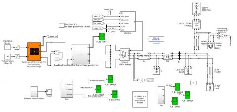
The Simulink model of the suggested system is explained below. In the modeled system, the input is given by solar power with temperature and irradiance as the input for a panel with a 7 module 88 parallel string with an MPPT control. The model consists of a buck-boost converter and an inverter system for which the input for the converter is providing the variables which are found from the feedback-controlled loop which uses a shunt active power filter with a fault current limiter. These variables are identified from the output of the packet wavelet transform which utilized the error deviation from the steady and transient states on the grid operation concerning the harmonic system response. The converter then varies its output based on the loading situation of the grid and regulates the error that is created due to multiple integrations of input sources and maintains the stability of power output. The output of the converter is sent to a synchronous inverter which maintains a smooth transition between grid mode and islanding mode which uses the comparison of demand power prediction with actual power incorporating triangular functions, thereby the system overload is mitigated by isolating the maximum load from the system when the actual utility is more than prediction demand. The smooth transition is affected by the contrast of balanced load phase angles at varying loading conditions.
Figure 2. Simulink model of the suggested system
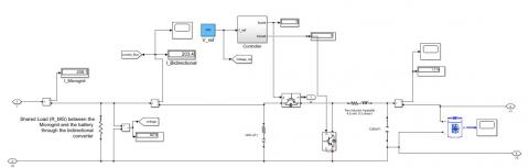
Figure 3. Feedback controlled converter
The Photovoltaic array model's initial input irradiance is 1000 W/m2 and the operating temperature is 45 degrees Celsius. When the array reaches steady-state, the mean PV voltage is 481 V, and the power harvested is 236 kW. The converter is represented using a PWM-controlled 3-level IGBT bridge that employs a VDC Regulator to calculate the active current reference for the current regulator. The regulator calculates the needed reference voltages for the inverter, which are set at 300 V, based on the reference current and reactive current. Here the model output is sent to three variable output loads correspondingly 250 kW, 2MW, and a grounding transformer through 8 km feeder and 14 km feeder respectively. The model of the suggested converter in the system is observed as below.
The converter utilizes the input from the system and compares the values with the load demand. If any deviation, then it uses a feedback loop with a shunt active filter. Shunt active filters are used to adjust current harmonics in nonlinear loads, as well as to balance imbalance currents and perform reactive power compensation. Hence to compensate for current harmonics or reactive load, a shunt active filter is introduced which senses the load current and injects a current into the system in case of variation. Control signals, in combination with a shunt active power filter in a fault current limiter, are used to reduce grid power and fault current. If there is any multiplicative input, the performance problem becomes a stability problem, and the performance problem becomes a stability problem which is reduced by controlling the output of the converter concerning demand.
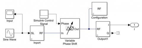
Figure 4. Balanced phase transition
From the converter, the signals are sent to the inverter in which balanced phase transition is done so that the output is stabilized. The system's load demand is determined, and this is compared to the utility load. It corresponds to the deviation of any variation and the input of the inverter is adjusted using a variable phase shift control for which the comparison is done through the sine wave signals from the load demand and load utility loads and then the additional loads are turned off and thus preventing overload thereby protecting from the system overloads.
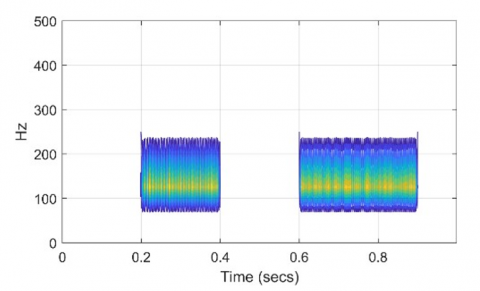
Figure 5. Frequency vs time
The time-frequency data of the suggested system is acquired using packet wavelet transforms. It identifies the frequency reply of the system concerning the transient & steady-state conditions. The obtained frequency for the system lies between 75 to 250 Hz for a period of 0.2 to 0.4 sec.
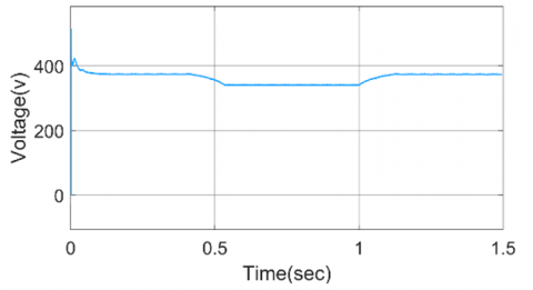
Figure 6. Voltage vs time
The system voltage is initially noted as 400 V and it gradually reduces till 0.6 sec and maintains constant till 1 sec and beyond that, the harmonic reply of the system is stabilized using the load phase angle response and is increased from 1 to 1.5 sec.
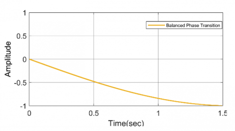
Figure 7. Amplitude vs time
The graph indicates the section of an initial half-sine wave from 0 sec to 1.5 sec. it is recognized that the amplitude of the sine wave in the balanced phase transition of the system is gradually reduced from 0 to 1.5 sec which indicates the isolation of the load if it exceeds the predicted load demand of the system.
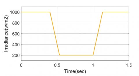
Figure 8. Irradiance vs time
The initial input irradiance to the Photovoltaic array model is 1000 W/m2 and the operating temperature is 45 deg. C. When steady-state is reached (around t=0.15 sec.), we get a PV voltage (Vdc_mean) of 400 V & the power extracted (Pdc_mean) from the array is 236 kW. At t=0.3 sec, solar irradiance is rapidly ramped down from 1000 W/m2 to 200 W/m2.
Figure 9. $\mathrm{P}_{\mathrm{dc}} \mathrm{vs}$ time
The initial power extracted to the system is 0 kW at noload conditions. When steady-state is reached (around t=0.15 sec.), we get a PV voltage (Vdc_mean) of 400V & the power extracted (Pdc_mean) from the array is 236 kW. At t=0.3 sec, solar irradiance is rapidly ramped down from 1000 W/m2 to 200 W/m2.
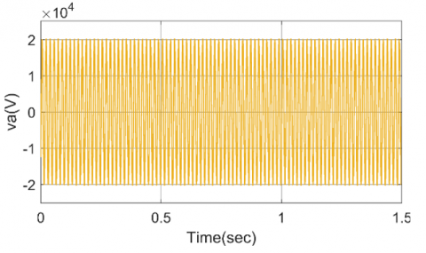
Figure 10. Va vs time
The active system voltage is depicted from the diagram mentioned above. The plot is a function of time that varies from 0 to 1.5 seconds. The load phase angle of the system is observed to vary from 0 to 2000 V in the positive sine wave. The overall observation of the voltage is observed to be constant from 0 to 1.5 sec and it is owing to the feedbackcontrolled converter that suppresses the error and maintains the stability of the system.
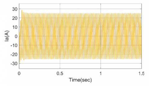
Figure 11. $\mathrm{Ia}$ vs time
Similarly, the system's fault current is mitigated using the shunt active power filter in the converter. It is detected that initially the current owing to the load is varied slightly to 275 A. The active current is then stabilized to a value of 250 A concerning loading and time.
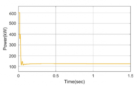
Figure 12. Power vs time
The power variation because of the loading is depicted in the graph. It is detected that initially the active power value is 600 Kw and due to loading it is reduced to 110 Kw with a slight oscillated variation. This fluctuation is overcome by adopting the feedback-controlled loop by which the power value is reduced from 600 kW and is then maintained at 125 kW. This is prepared by the utilization of comparison of the utility power & load demand and the isolation of overloads, hence maintaining the stability of the system.
The comparison of the proposed method with other techniques is discussed below with various techniques like PID, fuzzy logic, and artificial neural network.
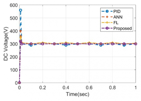
Figure 13. Comparison of DC voltage vs time
The comparison metrics of the DC voltage concerning time are depicted from the graph mentioned above. Various techniques like PID, ANN, and FL (PID, fuzzy logic, artificial neural network) [21] are taken into consideration. It is evident that for all the other techniques, the voltage is fluctuating and for our proposed method the value distortedm value at 0.01 sec is then maintained to be a constant at 300 V, and hence the strength of the system is enhanced for the proposed system.
Figure 14. Comparison of DC power vs Time
Figure 14 denotes the comparison of DC power as a function of time with various comparison techniques like PID, ANN, and FL. From the graph, it is depicted that for all the other techniques, the value of DC power for some time 0 to 1 sec is identified. For all techniques, there is a slight oscillation in DC power else for the proposed technique the value is maintained constant maintaining a stable output power.
Figure 15. Comparison of frequency vs time
The comparison of frequency as a function of time using various comparison methods such as PID, ANN, and FL is displayed in Fig. The value of DC power during a period of 0 to 1 sec is recognized for all other procedures, as displayed in the graph. There is a minor fluctuation in frequency for all strategies, but the suggested methodology, the value is kept constant, results in a steady output from 0.2 sec at 50.02 Hz.
Figure 16. Comparison of AC power vs time
The calculation of AC power as a function of time using different comparison methods such as PID, ANN, and FL is displayed in Figure. The value of AC power during a period of 0 to 1 sec is recognized for all of the other procedures, as displayed in the graph. However, the value for the suggested technique is kept constant, resulting in a steady output power after 0.5 sec at a value of $6.1 \times 10^4 \mathrm{~kW}$ which is maximum than other techniques.
This research has, Harmonic Response Technique that is used to increase power stability by determining distorted current waveforms that contribute to harmonic energy levels utilizing a Packet wavelet transform-based high impedance fault diagnosis. A Feedback controlled fault current limiting Converter is also used to decrease fault current distortion, which regulates the system using a shunt active power filter in a current fault limiter. Furthermore, a novel Balanced Phase Transition Technique balances power discrepancy in transition by determining energy consumption over the current demand period using reactive power & load factor of the converter using triangular functions, resulting in a balanced load phase angle and smooth transition between phases. Thus the adopted techniques are simulated in the MatLab platform and the outputs are obtained in terms of frequency for the system lies between 75 to 250 Hz, the system voltage is noted as 400 V, the amplitude is gradually reduced from 0 to 1.5 sec, the irradiance is rapidly ramped down from 1000 W/m2 to 200 W/m2, load phase angle of the system is observed to vary from 0 to 2000 V in the positive sine wave and the current because of the load is varied slightly to 275 A and the power from 600 kW is gradually reduced to 125 kW. Moreover, the proposed techniques performed better than other existing techniques and proved better performance.
|
$\mathrm{i}_{\mathrm{t}}$ |
analog current |
|
$\mathrm{v}_{\mathrm{t}}$ |
voltage waveforms |
|
T |
observation period |
|
$\mathrm{I}_{\mathrm{sp}}$ |
desired source current |
|
$\mathrm{I}_{\mathrm{sm}}$ |
real power |
|
$\mathrm{I}_{\mathrm{mL}}$ |
loss component |
|
$\mathrm{i}_{\mathrm{c}}$ |
the instantaneous value of filter current |
|
$\mathrm{i}_{\mathrm{L}}$ |
instantaneous value of load |
|
$\mathrm{i}_{\mathrm{s}}$ |
the instantaneous value of a source |
|
$\mathrm{d}_{\mathrm{j}, \mathrm{k}}^{\mathrm{i}}$, and $\mathrm{d}_{\mathrm{j}, \mathrm{k}}^{\mathrm{*i}}$ |
wavelet coefficients of $\mathrm{i}_{\mathrm{n}}$ and $\mathrm{v}_{\mathrm{n}}$ |
|
$\mathrm{i}_{\mathrm{n}}$ and $\mathrm{v}_{\mathrm{n}}$ |
digitized waveforms of $\mathrm{i}_{\mathrm{t}}$ and $\mathrm{v}_{\mathrm{t}}$ |
[1] Ai, Songpu, Antorweep Chakravorty, and Chunming Rong. (2019). Household power demand prediction using evolutionary ensemble neural network pool with multiple network structures. Sensors, 19 (3): 721. https://doi.org/10.3390/s19030721
[2] Peng, Jieyang, et al. (2021). Dual-stage attention-based long-short-term memory neural networks for energy demand prediction. Energy and Buildings, 249: 111211. https://doi.org/10.1016/j.enbuild.2021.111211
[3] Ghiasi, Mohammad. (2019). Detailed study, multi- objective optimization, and design of an AC-DC smart microgrid with hybrid renewable energy resources.Energy, 169: 496-507.https://doi.org/10.1016/j.energy.2018.12.083
[4] Elkadeem, M. R., et al. (2020). A systematic decisionmaking approach for planning and assessment of hybrid renewable energy-based microgrid with technoeconomic optimization: A case study on an urban community in Egypt. Sustainable Cities and Society, 54: 102013. https://doi.org/10.1016/j.scs.2019.102013
[5] Dawoud, Samir M., Xiangning Lin, and Merfat I. Okba. (2018). Hybrid renewable microgrid optimization techniques: A review. Renewable and Sustainable Energy Reviews, 82: 2039-2052. https://doi.org/10.1016/j.rser.2017.08.007
[6] Sepehrirad, Iman, et al. (2020). Intelligent differential protection scheme for controlled islanding of microgrids based on decision tree technique. Journal of Control, Automation and Electrical Systems, 31(5): 1233-1250. https://doi.org/10.1007/s40313-020-00588-7
[7] Mahdiraji, Ebadollah Amouzad, and Mojtaba Sedghi Amiri. (2021). Optimization of Electric Vehicles Along with Power Generation Units to Improve Microgrid Reliability. Quantum Journal of Engineering, Science and Technology, 2 (2): 1-15. https://doi.org/10.1016/j.etran.2020.100056
[8] Barbaro, Marco, and Rui Castro. (2020). Design optimisation for a hybrid renewable microgrid: Application to the case of Faial island, Azores archipelago. Renewable Energy, 151: 434-445. https://doi.org/10.1016/j.renene.2019.11.034
[9] Batiyah, Salem, et al. (2020). An MPC-based power management of standalone DC microgrid with energy storage. International Journal of Electrical Power & Energy Systems, 120: 105949. https://doi.org/10.1016/j.ijepes.2020.105949
[10] H. Farsizadeh, M. Gheisarnejad, M. Mosayebi, M. Rafiei, Khooban, M.H. (2019). An intelligent and fast controller for dc/dc converter feeding cpl in a dc microgrid. IEEE Transactions on Circuits and Systems II:.Express Briefs. https://doi.org/10.1109/TCSII.2019.2928814
[11] Mayer, Martin János, Artúr Szilágyi, and Gyula Gróf. (2020). Environmental and economic multi-objective optimization of a household level hybrid renewable energy system by genetic algorithm. Applied Energy, 269: 115058. https://doi.org/10.1016/j.apenergy.2020.115058
[12] Sun, Yushu, et al. (2020). Application of integrated energy storage system in wind power fluctuation mitigation. Journal of Energy Storage, 32: 101835. https://doi.org/10.1016/j.est.2020.101835
[13] Bullich-Massagué, Eduard, et al. (2020). A review of energy storage technologies for large scale photovoltaic power plants. Applied Energy, 274: 115213. https://doi.org/10.1016/j.apenergy.2020.115213
[14] Salameh, Tareq, et al. (2021). Integrated standalone hybrid solar PV, fuel cell and diesel generator power system for battery or supercapacitor storage systems in Khorfakkan, United Arab Emirates. International Journal of Hydrogen Energy, 46(8): 6014-6027. https://doi.org/10.1016/j.ijhydene.2020.08.153
[15] Kahwash, F., Maheri, A. and Mahkamov, K. (2021). Integration and optimisation of high-penetration Hybrid Renewable Energy Systems for fulfilling electrical and thermal demand for off-grid communities. Energy Conversion and Management, 236: 114035. https://doi.org/10.1016/j.enconman.2021.114035
[16] Sidorov, Denis, et al. (2020). Toward zero-emission hybrid AC/DC power systems with renewable energy sources and storages: A case study from Lake Baikal region. Energies, 13(5): 1226. https://doi.org/10.3390/en13051226
[17] Phan, Bao Chau, and Ying-Chih Lai. (2019). Control strategy of a hybrid renewable energy system based on reinforcement learning approach for an isolated microgrid. Applied Sciences, 9(19): 4001. https://doi.org/10.3390/app9194001
[18] Jha, Sumit Kumar, and Deepak Kumar. (2019). Demand side management for stand-alone microgrid using coordinated control of battery energy storage system and hybrid renewable energy sources. Electric Power Components and Systems, 47(14-15): 1261-1273. https://doi.org/10.1080/15325008.2019.1661544
[19] Elnozahy, Ahmed, et al. (2021). Performance improvement of hybrid renewable energy sources connected to the grid using artificial neural network and sliding mode control. Journal of Power Electronics, 1-14. https://doi.org/10.1007/s43236-021-00242-8
[20] Soundarya, G., et al. (2021). Design and Modeling of Hybrid DC/AC Microgrid With Manifold Renewable Energy Sources. IEEE Canadian Journal of Electrical and Computer Engineering, 44(2): 130-135. https://doi.org/10.1109/ICJECE.2020.2989222.
[21] Al Sumarmad, Khaizaran Abdulhussein, et al. (2022). Energy Management and Voltage Control in Microgrids Using Artificial Neural Networks, PID, and Fuzzy Logic Controllers. Energies, 15(1): 303. https://doi.org/10.3390/en15010303
[22] Jain, Shailendra Kumar, and Pramod Agarwal. (2003). Design simulation and experimental investigations, on a shunt active power filter for harmonics, and reactive power compensation. Electric Power Components and Systems, 31(7): 671-692. https://doi.org/10.1080/15325000390203674