Abhishek Agarwal
© 2022 IIETA. This article is published by IIETA and is licensed under the CC BY 4.0 license (http://creativecommons.org/licenses/by/4.0/).
OPEN ACCESS
Both offshore wind and hydrogen generation are increasingly seen as central to global decarbonization. The objective of current research is to investigate the effect of wind turbine height of Vertical Axis Wind Turbine (VAWT) on hydrogen generation. The numerical investigation of VAWT is conducted using techniques of Computational Fluid Dynamics. The VAWT design is developed in Solidworks design software and CFD analysis is conducted using ANSYS CFX software. The CFD analysis conducted on VAWT aided to determine the torque generated from it at 10m/s wind velocity determining the system impacts and ability of electrolyzer technology to accommodate the varying input from wind turbine. The research findings have shown that height of VAWT blade has significant effect on power generation. The power generation from VAWT increases with increase in blade height. The maximum hydrogen mass is generated for 850mm height wind turbine i.e., 2.09Kg. The external wind flow conditions have significant effect on power generation from VAWT and therefore the effect of varying air flow conditions needs to be investigated.
Wind turbine, hydrogen production, Polymer electrolyte membrane (PEM), CFD, hydrolysis
Wind energy is getting a lot of attention among all the available renewable sources as it is an inexhaustible, environment-friendly, and completely free energy source. Its advantages make it the most prominent method for the generation of sustainable energy [1]. Wind energy doesn’t cause the emission of harmful gases like carbon dioxide and other greenhouse gases. With the use of wind energy, dependency on fossil fuels is decreased significantly [2] . However, it has some limitations like inconsistent regularity of wind, the need for complicated setups in order to convert wind energy to another energy carrier with the help of turbines, transportation and storage problems [1]. Moreover, the generation of electricity by the wind turbine system below its capability, known as wind curtailment, is also an issue that requires consideration [3]. The hydrogen energy system can be the best alternative solution to the limitations of wind energy. Hydrogen can be generated from renewable energy sources like the wind without causing any harmful gases and pollutants. It is sustainable and clean, can be stored, and an efficient energy source makes it suitable to be called the fuel of the future [1,4]. Other advantages of hydrogen energy include high energy density i.e 120 – 142 MJ per kg and high conversion efficiency [4]. This paper reviews the necessary requirements and basic principle of the wind-hydrogen energy system and also based on a study conducted in Afghanistan, suggest future research work in this area for developing and undeveloped nations. The integration of hydrogen at wind farms can resolve wind curtailment as it facilitates flexibility to shift generation to match market factors and operational needs to resource availability [5]. The hydrogen generation system with wind energy directly produces electricity using turbines or with water electrolysis to generate hydrogen, hence it is an efficient and clean source of energy [1].
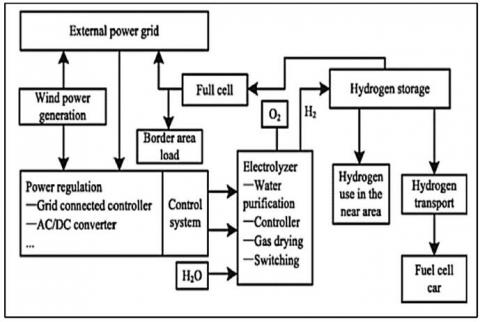
The basic structure of the wind energy-hydrogen system is illustrated in Figure 1.
Figure 1. Basic structure of wind energy-hydrogen system [3]
The wind turbines not only provide energy to the power grids, but the excess electricity also causes the hydrolysis of water and generates hydrogen [5]. The generated hydrogen energy can be stored and then can be used for multiple applications such as fuel in vehicles and electricity generation etc. This can be an alternative way to energy production on small scale in a remote area where wind energy can’t be generated [6]. The area of use and type of application is the deciding factors for the design characteristics of the wind turbine. The cut-out speed is a safety feature that protects wind turbines from damage [7].
Thirugnanasambandham et al. [8] studied hydrogen generation from wastewater of chicken industry with an electrochemical process in an up-flow blanket reactor. It was observed that optimization of electrochemical process for treating wastewater of chicken industry is well matched by Response Surface Methodology (RSM) which is based on the BBD. The study investigated numerous independent variable electrochemical processes like electrode surface area, hydraulic retention time, and current density. The maximum hydrogen gas (0.8 mL/L) is generated when the electrochemical process has 5 m2 of electrode surface area, 30 min of hydraulic retention time, and 15 A/m2 of current density. Ansori et al. [9]examined palm oil mill effluent (POME) for the generation of hydrogen gas. The hydrogen is generated by electrolysis of POME having no additive or pretreatment, with the electricity of 2-4 V with 20 L of reactor and aluminum electrodes. Using this process, the maximum gas of about 22.68 L h-1 was generated with 62% of turbidity of POME and 57% efficient reductions of COD. Phalakornkule, Pisut, and Chinnarat [10] generated hydrogen gas of about 0.521 × 10³ m3 (6.252 × 10⁶ L h−1) from dyes containing wastewater using the electrochemical process in 5 min. The electrocoagulation process is used to treat dye- containing wastewater and generate hydrogen gas. This study showed that a gas separation tank that follows a conventional up-flow anaerobic sludge bed can significantly increase the generation of hydrogen gas. The energy generated by the produced hydrogen is 0.2 kWh m-3.
Tsurutani, and Umeda [11] studied the electrolysis of methol-water solution for the generation of hydrogen gas. The cathode exhaust gas is filled with carbon dioxide and hydrogen gas, the hydrogen gas concentration is 95.5–97.2 mol%.
S V R Wilson, et al. [12] explained the determination of moments of root bending on wind turbine having 500 W 3- blade horizontal axis for obtaining rotating data acquisition system. This work mainly aimed integration of moments when wind direction changes cause turbine yawing especially when turbine yow rates are high. The largest loads are caused by small operating turbines in this situation. When the turbine yow rates are sufficiently high, the cyclic Coriolis acceleration by the yawing and rotating blades contributes a significant moment. The investment required for storage of hydrogen is still high. The conversation of electricity in to hydrogen and vice versa in not economical at this stage [13].
Peter J. Schubel. et al. [14] reviewed designs of wind turbine blades including propulsion practical efficiency, theoretical maximum efficiency, and HAWT blade design and blade 100 ds. The full picture of designs of wind turbine blades and the dominance of modern turbines with horizontal axis rates is presented. It explained principles of aerodynamic design door modern turbine consisting of options attack angles, quant aero fail selection and blades plan shape. It also described gyroscopic, gravitational, aerodynamic, centrifugal, and operational conditions.
S. Bahramiasl, et al. [15] provide details of offshore wind turbines. An offshore wind turbine is fabricated and tested for various wind heading angles and rotor rotation velocities to obtain impact their impact on blade structure responses. It is observed that under environmental loads, the response of wind turbines has remarkable importance as structure behavior can greatly influence the process of wind turbine structure optimization and modeling. It is concluded that wind heading angle may change spectrum behavior affected by rotor velocity.
Hiromichi Akimoto, et al. [16] explained the concept of a Floating Axis Wind Turbine (FAWT) in which the rotating cylindrical float act as a turbine shaft for the Vertical Axis Wind Turbine (VAWT). The buoyancy supported the heavy rotors and flexible joints are used to connect it to the power take-off system. So, it has not to be kept in the rigid upright position of the wind turbine. The cost of the system and supporting structure is reduced in the work. The flexibly supported turbine is stabilized by the gyroscopic effect on the VAWT rotor. The proposed turbine is tested at regular wave conditions that result in precession motion about the balanced tilt position of the turbine axis. Abhijit Mane, et al [17] observed that the wind turbines are just 59% efficient and the large rotors need very large spacing between two turbines for large wake formation. Thus, the conventional method of wind energy generation with an innovative approach result in a through-off gain. In this work, a gyro action-based e- generator with a bladeless vortex wind turbine is designed and developed for producing electricity. It is modeled using 3D printing and tested to measure the impact of wind speed on the current, voltage, power, and speed of the turbine.
David JesúsYáñez [18] compared conventional wind turbines with the new wind generators with different features and characteristics. The introduction of magnetic forces to the resonant structures facilitates the modification of rigidity of the structure that results in increased lock-in range. For converting oscillating motion into electricity, electromagnetic induction is one of the methods available methods. Akshay Agrawal et al. [19] designed a windmill that is totally different from the available traditional windmills in which has a crankshaft, a crank, conical frustum mast composed of fiberglass, a hinge joint, and a connecting rod instead of typical blades, nacelle, and the huge tower. The windmill is user-friendly and portable due to its lightweight and hollow mast. Moreover, it is a low-cost way of generating energy.
Rishabh Ojha et al. [20] designed a turbine that is entirely different from conventional turbines. This keeps the technology for such projects at a very low threshold of capital intensity that makes it highly competitive against both alternative or renewable energy generators and traditional technologies. The bladeless wind system and its corresponding results are explained that can be helpful in the development of future bladeless wind energy production systems. To generate power in the bladeless wind energy generator has a different force than that of the conventional wind turbine.
Davang Shubham s. et al. [21] provided details about bladeless wind turbine and show it is a prominent method of generating electricity as it has various advantages like economical and efficient method.
The presented study is intended to investigate the feasibility of vertical axis wind turbine in hydrogen gas generation using Polymer electrolyte membrane (PEM) electrolyzer. The amount of power generation from vertical axis wind turbine is determined using techniques of Computational Fluid Dynamics [22] . The yield of hydrogen is then calculated on the basis of power generated from VAWT. The CFD analysis of VAWT is conducted using ANSYS CFX.
The methodology involves determining torque generated from VAWT using ANSYS CFX simulation package. The tool used for analysis is CFD which is based on Navier–Stokes equations [23]. The Navier stokes equation is based on mass, momentum, and energy conservation principle. The turbulence model used for the analysis is k-omega.
The Navier–Stokes equations could be expressed as follows:
$\frac{\partial}{\partial x}\left(\rho u_i\right)=0$ (1)
$\frac{\partial}{\partial x}\left(\rho u_i u_k\right)=-\frac{\partial P}{\partial x}+\frac{\partial}{\partial x}\left(\mu \frac{\partial u_k}{\partial x}\right)$ (2)
$\frac{\partial}{\partial x}\left(\rho u_i T\right)=-\frac{\partial}{\partial x}\left(\frac{\partial T}{\partial x} \frac{k}{c_p}\right)$ (3)
where u is the fluid velocity [m/s], ρ is the fluid density [kg/m3], P is the static pressure [Pa].
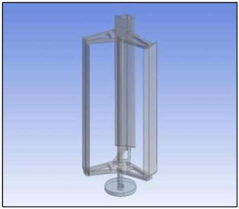
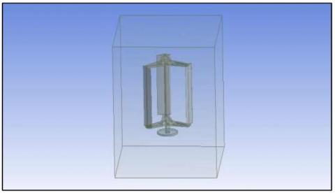
The VAWT design is developed using Solidworks design software. The NACA 0012 air foil is considered for blade design with three different heights [24]. The height of VAWT considered for analysis is 400mm, 600mm and 800mm range. The VAWT design developed in solid works is then converted in .iges file format and imported in ANSYS design modeller as shown in figure 2 below.
Figure 2. Imported CAD model of wind turbine with 450mm height
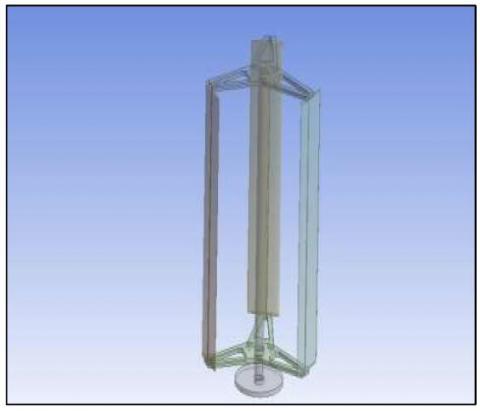
Figure 3. Imported CAD model of wind turbine with 650mm height
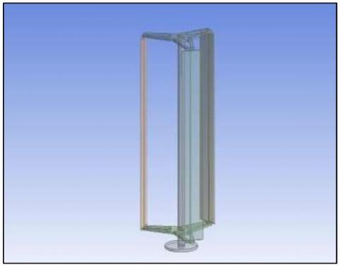
Figure 4. Imported CAD model of wind turbine with 850mm height
The VAWT with 400mm, 650mm and 850mm is shown in figure 2, figure 3 and figure 4 above. An enclosure is developed surrounding the VAWT. The dimensions of enclosure surrounding VAWT are .5m *1m* .5m. The developed enclosure is shown in figure 5 below.
Figure 5. Enclosure modelling
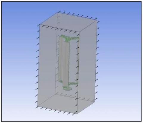
Figure 6. Discretized model of enclosure
The enclosure with VAWT is meshed as shown in figure 6. The meshing process involves conversion of solid model in to meshed model. The mesh settings are set to fine, and inflation set to 1.3. The number of elements generated is 4164925 and number of nodes generated is 789547 followed by a grid independence test. Two different domain types are defined for the CFD analysis. The fluid type domain is defined for external wind flow and solid domain is defined for turbine blade, shaft.
Figure 7. Boundary condition for computational domain
The air inlet, air outlet boundary conditions are defined as shown in figure 7. The air inlet is defined with 10.3m/s and turbulence model set to k-omega. The reference pressure computational domain is set to 1 atm. The rear face of computational domain is defined with null relative pressure difference. The convergence criteria are defined for the simulation. The RMS residual target values are defined as .0001 and maximum number of iterations set to 300.
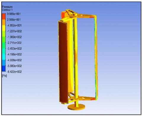
The CFD simulation is conducted on VAWT with different heights i.e., 450mm, 650mm and 850mm. The pressure exerted on VAWT structure of 450mm height is determined as shown in figure 8 below. Both compressive and tensile pressure is generated on the VAWT structure. The tensile pressure is generated on blade edges and on inner side of blade whereas compressive pressure is generated on leeward side of blade as represented in red coloured zone of figure 9.
Figure 8. Pressure plot on VAWT (450mm height)
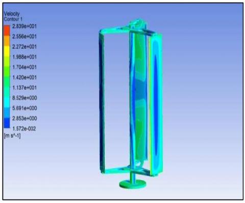
Figure 9. Velocity plot on VAWT (450mm height)
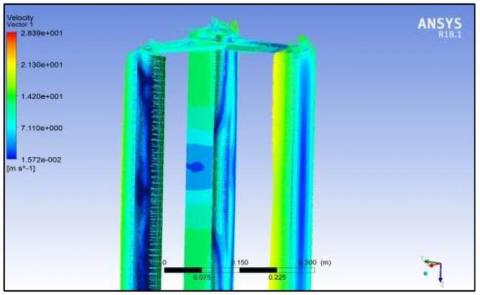
The velocity plot is generated for VAWT with 450mm height. The velocity at the blade tip is maximum and is minimum at the center region of blade. The maximum velocity obtained from the analysis is nearly 28m/s nearly. This is evident from vector plot shown in figure 10 below.
Figure 10. Velocity vector plot on VAWT (450mm height)
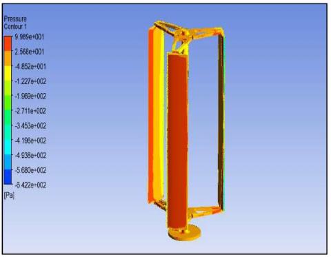
In the figure 11, the pressure plot is generated for VAWT with 650mm height, and the maximum compressive pressure generated is 98.9Pa whereas the inner face has tensile pressure with magnitude of 48.5Pa.
Figure 11. Pressure plot on VAWT (650mm height)
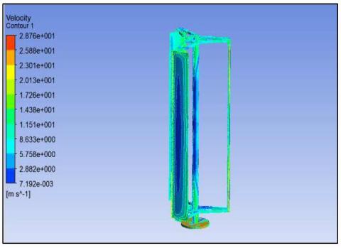
The velocity plot is generated for VAWT with 650mm height as shown in figure 12. The maximum velocity is obtained at the blade tip with magnitude of 19.8m/s and minimum velocity is observed at the center of blade with magnitude of 2.85m/s.
Figure 12. Velocity plot on VAWT (650mm height)
The pressure plot is generated for VAWT with 850mm height, and the maximum compressive pressure generated is 106.5Pa whereas the inner face has tensile pressure with magnitude of 43.8Pa as shown in figure 13.
Figure 13. Pressure plot on VAWT (850mm height)
The velocity plot is generated for VAWT with 850mm height as shown in figure 14 below. The maximum velocity is obtained at the blade tip with magnitude of 28.7m/s and minimum velocity is observed at the center of blade with magnitude of 2.88m/s.
Figure 14. Velocity plot on VAWT (850mm height)
From the CFD analysis, the torque is determined for all the 3 VAWT height i.e., 450mm, 650mm and 850mm. The torque generated by VAWT of different height is shown in table 1.
Table 1. Torque generation
|
Height (mm) |
450mm |
650mm |
850mm |
|
Torque (Nm) |
1.5682 |
2.98 |
3.97 |
The vertical axis wind turbine is operating at 252RPM. The power generated is evaluated for different height of VAWT@252 rpm.
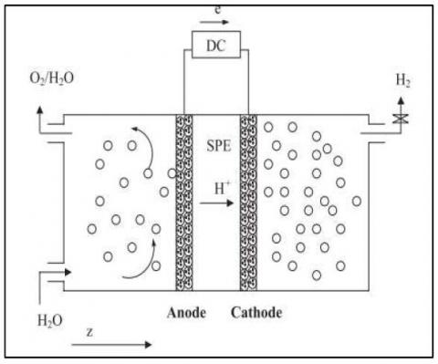
Polymer membranes are used as electrolytes in PEM. The electrolysers, which are likely to profit from the mass production of PEM fuel cells, can benefit greatly from the heavy technological development that is currently taking place in PEM fuel cells. Even though PEM electrolysers are a more recent technology than alkaline electrolysers, there are already a number of them on the market. Although up to 94 percent efficiency factors for PEM electrolysers are predicted, this is still only a prediction at this time. PEM electrolyzer currently have lower efficiency factors than the best alkaline electrolysers. The hydrogen yield is determined for Polymer electrolyte membrane (PEM) electrolyzer i.e., solid polymer electrolyzer as shown in figure 15.
Figure 15. Cross-section of Polymer electrolyte membrane (PEM) [25]
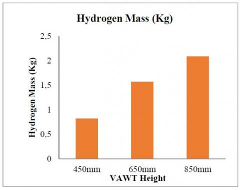
The power consumption in 1Kg industrial production of hydrogen by Polymer electrolyte membrane (PEM) electrolyzer is nearly 50KWh [26]. On the basis of this data, the yield of hydrogen is evaluated for power generated from vertical axis wind turbine. The hydrogen yield is evaluated on the basis of power generated from vertical axis wind turbine as shown in figure 16.
Figure 16. Cross-section of Polymer electrolyte membrane (PEM) electrolyzer
The power generation from VAWT increases with increase in blade height. The maximum hydrogen mass is generated for 850mm height wind turbine.
The numerical investigation conducted on vertical axis wind turbine has shown viability of Vertical Axis Wind Turbine (VAWT) in hydrogen generation using Polymer electrolyte membrane (PEM) electrolyzer. The CFD analysis conducted on Vertical Axis Wind Turbine (VAWT) aided to determine the torque generated from it at 10m/s wind velocity. The research findings have shown that height of VAWT blade has significant effect on power generation. The power generation from Vertical Axis Wind Turbine (VAWT) increases with increase in blade height. The maximum hydrogen mass is generated for 850mm height wind turbine i.e., 2.09Kg. The external wind flow conditions have significant effect on power generation from VAWT and therefore the effect of varying air flow conditions needs to be investigated and further monetary analysis can also be done based on comparison with experimental prototype and with other energy sources.
[1] M. Douak, N. Settou, Estimation of Hydrogen Production Using Wind Energy in Algeria, Energy Procedia. 74 (2015) 981–990. https://doi.org/10.1016/j.egypro.2015.07.829.
[2] Agarwal A., P. I., M.T. Letsatsi, Thermodynamic analysis of wind catcher with cooling pads using SSG Reynolds stress turbulence model, J. Eng. Res. 9 (2021) 1–13. https://doi.org/10.36909/jer.ICIPPSD.15507.
[3] Z. Li, P. Guo, R. Han, H. Sun, Current status and development trend of wind power generation-based hydrogen production technology, Energy Explor. Exploit. 37 (2019) 5–25. https://doi.org/10.1177/0144598718787294.
[4] M. Rezaei, N. Naghdi-Khozani, N. Jafari, Wind energy utilization for hydrogen production in an underdeveloped country: An economic investigation, Renew. Energy. 147 (2020) 1044–1057. https://doi.org/https://doi.org/10.1016/j.renene.2019. 09.079.
[5] Hydrogen Production: Electrolysis, Hydrog. Fuel Cell Technol. Off. (n.d.). https://www.energy.gov/eere/fuelcells/hydrogen- production-electrolysis (accessed November 19, 2021).
[6] M. Gökçek, Hydrogen generation from small-scale wind-powered electrolysis system in different power matching modes, Int. J. Hydrogen Energy. 35 (2010) 10050–10059. https://doi.org/https://doi.org/10.1016/j.ijhydene.201 0.07.149.
[7] Mike Rycroft, Enabling wind turbines to operate at high wind speeds, Artic. EE Publ. (2015). https://www.ee.co.za/article/enabling-wind-turbines- operate-high-wind-speeds.html (accessed October 10, 2021).
[8] K. Thirugnanasambandham, V. Sivakumar, Removal of ecotoxicological matters from tannery wastewater using electrocoagulation reactor: modelling and optimization, Desalin. Water Treat. 57 (2016) 3871– 3880. https://doi.org/10.1080/19443994.2014.989915.
[9] M.A. Nasution, Z. Yaakob, E. Ali, S.M. Tasirin, S.R.S. Abdullah, Electrocoagulation of palm oil mill effluent as wastewater treatment and hydrogen production using electrode aluminum., J. Environ. Qual. 40 (2011) 1332–1339. https://doi.org/10.2134/jeq2011.0002.
[10] C. Phalakornkule, P. Sukkasem, C. Mutchimsattha, Hydrogen recovery from the electrocoagulation treatment of dye-containing wastewater, Int. J. Hydrogen Energy. 35 (2010) 10934–10943. https://doi.org/https://doi.org/10.1016/j.ijhydene.201 0.06.100.
[11] T. Take, K. Tsurutani, M. Umeda, Hydrogen production by methanol–water solution electrolysis, J. Power Sources. 164 (2007) 9–16. https://doi.org/https://doi.org/10.1016/j.jpowsour.200 6.10.011.
[12] S.V.R. Wilson, P.D. Clausen, D.H. Wood, Gyroscopic moments on small wind turbine blades at high yaw rates, Aust. J. Mech. Eng. 5 (2008) 1–8. https://doi.org/10.1080/14484846.2008.11464529.
[13] P. Menanteau, M.M. Quéméré, A. Le Duigou, S. Le Bastard, An economic analysis of the production of hydrogen from wind-generated electricity for use in transport applications, Energy Policy. 39 (2011) 2957–2965. https://doi.org/10.1016/j.enpol.2011.03.005.
[14] P.J. Schubel, R.J. Crossley, Wind turbine blade design, Energies. 5 (2012) 3425–3449. https://doi.org/10.3390/en5093425.
[15] S. Bahramiasl, M. Abbaspour, M. Karimirad, Experimental study on gyroscopic effect of rotating rotor and wind heading angle on floating wind turbine responses, Int. J. Environ. Sci. Technol. 15 (2018) 2531–2544. https://doi.org/10.1007/s13762-017- 1519-4.
[16] H. Akimoto, K. Tanaka, Y. Hara, Gyroscopic effects on the dynamics of floating axis wind turbine, in: Gd. Renew. ENERGY 2014 Abstr. 2014 Proc., Tokyo Big Sight, Tokyo Japan, 2014: pp. 1–4.
[17] Abhijit Mane, M. Kharade, P. Sonkambale, Design & Analysis of Vortex Bladeless Turbine With Gyro E- Generator, Int. J. Innov. Res. Sci. Eng. 3 (2017) 445– 452.
[18] David J. Yáñez, VIV resonant wind generators, 2018. https://www.researchgate.net/publication/331345449_VIV_resonant_wind_generators.
[19] S. Sarkar, A. Agrawal, A. Sheth, Research Paper on Bladeless Windmills Based on The Principle of Vibration, Int. J. Sci. Res. 6 (2017) 13–16.
[20] R. Ojha, S. Behera, S. Bhuyan, V.K. Singh, Bladeless Wind Power Generation, Int. J. Sci. Dev. Res. 2 (1704) 163–167. www.ijsdr.org.
[21] D. Shubham, S. Manade, G.K. Patil, Patil Pavan, Bladeless Wind Turbine, Int. J. Innov. Eng. Res. Technol. 5 (2018) 2549–2553. http://ijraset.com/fileserve.php?FID=14871.
[22] A. Agarwal, Modelling & Numerical Investigation of the Effectiveness of Plate Heat Exchanger for Cooling Engine Oil Using ANSYS CFX, Int. J. Heat Technol. 39 (2021) 653–658. https://doi.org/10.18280/ijht.390237.
[23] A. Agarwal, L. Mthembu, CFD analysis of conical diffuser under swirl flow inlet conditions using turbulence models, Mater. Today Proc. 27 (2020) 1350–1355. https://doi.org/10.1016/j.matpr.2020.02.621.
[24] NACA 0012 AIRFOILS (n0012-il), Airfoil Tools. (n.d.). http://airfoiltools.com/airfoil/details?airfoil=n0012-il (accessed December 20, 2021).
[25] P. Choi, D.G. Bessarabov, R. Datta, A simple model for solid polymer electrolyte (SPE) water electrolysis, Solid State Ionics. 175 (2004) 535–539. https://doi.org/https://doi.org/10.1016/j.ssi.2004.01.0 76.
[26] B. Kruse, S. Grinna, C. Buch, Hydrogen: Status og Muligheter, 2002. http://bellona.org/filearchive/fil_Hydrogen_6- 2002.pdf.