Modelling and Performance Evaluation of 18w PEM Fuel Cell Considering H2 Pressure Variations

Neerudi Bhoopal | Dokku Sivanaga Malleswara Rao | Nagineni Venkata Sireesha | Idamakanti Kasireddy | Ranjith Kumar Gatla | Devineni Gireesh Kumar*
© 2022 IIETA. This article is published by IIETA and is licensed under the CC BY 4.0 license (http://creativecommons.org/licenses/by/4.0/).
OPEN ACCESS
The chemical energy of a hydrogen-oxygen reaction is converted directly into dc electrical energy by fuel cells (FC). PEMFCs (Proton Exchange Membrane Fuel Cells) are a feasible alternative for electrical transportation and stationary applications. This paper presented a PEMFC modelling approach using Artificial Intelligence. The main objective of this research is to build a model of an 18w Polymer Electrolyte Membrane (PEM) fuel cell and test its performance under different hydrogen pressure conditions. The physical model of the 18W hydrogen fueled PEM fuel cell is designed and tested at BHEL R&D. Additionally, a method for predicting a PEMFC's operating temperature using the voltage and current measures is suggested and successfully tested. However, the proposed technique is validated using experimental data from an 18W fuel cell. The analytical data and testing procedures required for determining the parameter values used in the proposed model are specified.
Due to high efficiency, zero-emissions when running on pure hydrogen, and low operating temperature, proton exchange membrane fuel cells (PEMFC) are considered a potential green power source for electrical transportation and stationary applications. Designing a power converter capable of conditioning the output power with high efficiency and reliability is the major challenge of PEMFC systems. The power converters are responsible for about 80% of the damage in the PEMFC system. The power converter must be tested and altered with a valid PEMFC during the design phase, and it must therefore be validated. However, the design and implementation of a PEMFC, including auxiliaries such as air compressor control testing, power and energy management, and performance optimization, will readily destroy a PEMFC. Furthermore, the cost of testing (hydrogen utilization and secured facility requirements) is also high for experiments with a realistic PEMFC.
These drawbacks highlight the critical importance of developing a real-time PEMFC emulator based on a model material for HIL applications (Hardware In the Loop). Power converters and auxiliaries can be validated and augmented in real-time with a PEMFC emulator during the design process of the PEMFC power system, with no risk to the stack and low system running cost. PEMFC modelling has sparked a lot of interest in the literature, where it's generally done with sophisticated models based on the understanding of the physicochemical phenomena [1-3]. These models require a strong knowledge of the parameters and how it works [4-7]. These parameters for PEMFC systems are generally not easy to determine. A PEMFC stack's transient behavior pattern is presented in [8]. However, the intrinsic parameters of the membrane and electrode overflowing and drying should be identified as the ohms resistance. These internal parameters are meaningful if the cell voltage is considered, although the necessary Parameters were not considered in this mathematical model. Hybrid models could meet these challenges. A PEMFC model has been built in [9], distinguishing the cell either in a constant or transient state. The suggested model, combined with the electric circuit and the empirical models, is consistent with experimental findings. However, only a small range of this model is accurate.
However, behavioral modelling can be achieved without all these parameters being identified employing a model known as the "black box." These models are based on factors that can be easily measured, such as temperature, pressure or cell current, and the output voltage of the PEMFC is estimated. Currently, the literature does not include dynamic models of PEMFC systems based on Artificial Networks (ANN). However, several models with significantly stable results [10-13] have been developed. A static and dynamic ANN-based PEMFC model was suggested in [13], with experimental findings. The proposed model uses the temperature measurements, the fuel cell current, the two gases' stoichiometry, and moisture. This modelling approach produces good results, but it suffers from an adverse temperature change. In [14], the high-power PEMFC neuronal modelling is shown in which temperature development is considered. However, the suggested model is static because of the non-recurring structure of the ANN [13]. Furthermore, the temperature at the anode circuit and in the water tank is measured, not providing the fuel cell with a precise operating temperature. An infrared camera was used in [15] to enhance temperature acquisition in the cells.
In this work, a new modelling approach is introduced to the PEMFC to provide a characteristic of stack voltage and evaluate its performances based on Artificial Intelligence. The "black box" approach consists of dynamical neural modelling with recurrent AI structure to predict the PEMFC voltage and operating temperature using experimental data with a high level of accuracy.
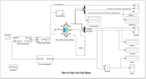
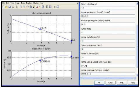
The fuel cell stack block implements a generic model parameterized to represent the most popular fuel cell stacks fed with hydrogen and air. This model is based on the equivalent circuit of a fuel cell stack shown in figure 1. The simplified model shown in figure 2 represents a particular fuel cell stack operating at nominal temperature and pressure conditions. Figure 3 illustrates the simulation parameters of 4 cell fuel stack. The equivalent circuit parameters can be modified based on the polarization curve obtained from the manufacturer's datasheet. The input in the masked the value of the voltage at no load and the nominal and the maximum operating points for the parameters to be calculated. A diode is used to prevent negative current flow into the stack. The model represents a particular fuel cell stack when the parameters such as pressures, temperature, compositions, and flow rates of fuel and air vary. The parameters are selected to vary on the signal variation. The variations affect the open-circuit voltage as well as the tafel slope. If the fuel and airflow rate is not provided, it is assumed that the stack is operating at a fixed rate of conversion of gases (nominal rate of conversion).
Figure 1. 18w 4cell fuel stack simulation block diagram
The supply of gases is adjusted according to the current so that they are always supplied with just a bit more than needed by the stack at any load. The maximum current the stack can deliver is limited by the maximum flow rates of fuel and air that can be reached. Beyond that limiting current, the voltage output by the stack decreases abruptly as more current is drawn. The dynamics of the fuel cell are represented if you specify the response time of the stack on the fuel cell dynamics pane on the dialogue box. This response time is used to model the charge double layer phenomenon, affecting only the activation overvoltage.By using equations(1 & 2) constructed the fuel cell model. This research constructed and simulated the results in the 4-cell stack simulation model, 35 and 120 cell models.
$R_{\text {ohm }}=R_{\text {int }}=\xi_{5}+\xi_{6} T+\xi_{7} I$ (1)
$\frac{d V_{\mathrm{act}}}{d t}=\frac{I}{C}-\frac{V_{\mathrm{act}} / R_{\mathrm{a}}}{C}$ (2)
Figure 2. 18w 4cell fuel stack simulation model
Figure 3. 18w 4cell fuel stack simulation parameters, voltage and power
In this work, the practical design model, mathematical model and simulated program were compared. The PEMFC is simulated by using MATLAB. The pressure increases at the anode, and the output voltage, current and efficiency are observed for the mathematical model. Similarly, the pressure increases at the anode and the output voltage, current and efficiency are kept for the practical model. Finally, we compared those results. Fuel cells open-circuit voltage (OCV) increased with increasing pressure. Increased pressure can effectively improve both the fuel cells reaction kinetics and the mass transfer process, resulting in improved fuel cell performance.
The prediction of an 18W fuel cells system using the BP networks is investigated. The simulation results indicate that BP networks can successfully predict the stack voltage of the FCS by using two input variables like hydrogen pressure and stack current in case 1. In case 2, input parameters are seven and output parameters five are considered. Input variables are hydrogen composition, oxygen flow rate, system temperature, hydrogen pressure and oxygen pressure. The out parameters are stack voltage, hydrogen, utilization of oxygen, stack efficiency and stack power. The speed of training and the prediction accuracy of NN is quite satisfactory.
Figure 4. V-I Characteristics for different pressures
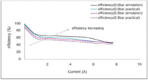
Figure 5. Efficiency at different pressures
Fuel cells stack is practically constructed, and tests are conducted. Here pressure and load are the varied inputs on the stack, and the output parameters like voltage, current and efficiency of the fuel cells are observed. From figures 4 & 5, it is observed that an increase in current density at different pressure proportionally increases operating voltage & efficiency, respectively.
Using Simulink, the simulation model for the 18w 4cell stack is developed with mathematical model equations, and tests are conducted on the simulation model. The developed simulation model consists of the input parameters like pressure, composition, and flow rates w.r.t to fuel & air and temperature. Fuel pressure is found to be a good input parameter to validate the simulated model results against practical model results. When the current density is varied at different pressures, the output parameters of fuel cell-like voltage and efficiency are proportionally varied. Referring to Table 1, the results observed from the simulation model and practical model are approximately equal, so the developed simulation model can be used for further analysis.
The output results of the simulated model {voltage, current, power, utilization (02 & H2) and consumption (O2 & H2)} observed that load is varied at different pressures (H2) & flow rates (H2). The output results of the simulated model (no-load voltage) were observed by varying the following parameters pressure (H2 & O2), flow rate (H2 & O2), temperature, composition (H2 & O2), which is displayed in table 1. It is observed that no-load voltage is more significant when the temperature is varied when compared with other input parameters like pressure (H2 & O2), flow rate (H2 & O2), composition (H2 & O2).
Table 1. Practical and simulation comparison of load variation on FEMFC
|
S. No |
Current (A) |
Pressure at 0.5 bar |
Pressure at 0.6 bar |
||||||
|
Simulation Results |
Practical Results |
Simulation Results |
Practical Results |
||||||
|
Voltage (Volts) |
Efficiency (%) |
Voltage (Volts) |
Efficiency (%) |
Voltage (Volts) |
Efficiency (%) |
Voltage (Volts) |
Efficiency (%) |
||
|
1 |
0 |
4.81 |
96 |
4.41 |
89.63 |
4.82 |
97 |
4.42 |
90.03 |
|
2 |
1 |
3.3 |
66 |
2.9 |
58.94 |
3.45 |
69 |
2.95 |
59.96 |
|
3 |
2 |
3.1 |
62 |
2.7 |
54.87 |
3.3 |
66 |
2.8 |
56.91 |
|
4 |
3 |
3 |
60 |
2.6 |
52.84 |
3.25 |
65 |
2.65 |
53.86 |
|
5 |
4 |
2.9 |
58 |
2.5 |
50.81 |
3.16 |
63.2 |
2.56 |
52.03 |
|
6 |
5 |
2.7 |
54 |
2.4 |
48.78 |
3.08 |
61.6 |
2.48 |
50.41 |
|
7 |
5.7 |
2.5 |
50 |
2.3 |
46.74 |
2.94 |
58.8 |
2.34 |
47.56 |
|
8 |
6.6 |
2.3 |
46 |
2.2 |
44.71 |
2.55 |
51 |
2.25 |
45.73 |
|
9 |
7.5 |
2.2 |
44 |
2.1 |
42.68 |
2.31 |
46.2 |
2.12 |
43.09 |
|
10 |
7.7 |
2.2 |
44 |
2.1 |
42.68 |
2.31 |
46.2 |
2.11 |
42.89 |
The Transient simulation model was developed and validated with benchmark results. The results observed from the simulation and benchmark models were approximately equal, so the developed Transient model can be used for further analysis. Concerning the literature and tests conducted on the dynamic model, the dynamic simulation model for the stack developed was based on the dynamical equations. The developed dynamic model consists of the input parameters like pressure, composition, and flow rates w.r.t to fuel, air and temperature. To validate the dynamic model results against literature benchmark model results, the fuel cell system level model constructed using simulation. The various system level model includes compressor, membrane hydration, anode channel model, cathode channel model, energy balance model, stack voltage model and capacitance equivalent circuit model developed.
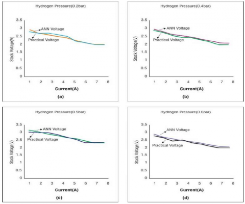
The ANN model for the 18w 4cell stack was developed based on the practical results of the physical model, and tests are conducted on the ANN model. The developed ANN model consists of the input parameters like pressure, composition, and flow rates w.r.t to fuel & air and temperature. Fuel pressure is used as an input parameter to validate the ANN model results against practical model results. When the current density is varied at different pressures, the output parameters of fuel cell- like voltage is proportionally varied. This can be observed in figure 6. The simulation results indicate that BP networks can successfully predict the 18w stack voltage of the FCS by using only two input parameters (hydrogen pressure & accumulation current) and one output parameter voltage. The results observed from the ANN model and practical model are approximately equal, so the developed ANN model can be used for further analysis.
Table 2. Comparison of practical and simulation results from FEMFC using ANN model
|
S. No |
Current (A) |
Test Cases |
|||||||||||
|
H2pressure 0.2 bar |
|
H2pressure 0.4 bar |
|
H2pressure 0.5 bar |
H2pressure 0.6 bar |
|
|||||||
|
Practical (V) |
ANN (V) |
Error (V) |
Practical (V) |
ANN (V) |
Error |
Practical ANN (V) (V) |
Error |
Practical (V) |
ANN (V) |
Error |
|||
|
1 |
1.00 |
2.700 |
2.60 |
0.10 |
2.800 |
2.90 |
0.10 |
2.900 |
2.80 |
0.10 |
2.950 |
2.89 |
0.06 |
|
2 |
2.00 |
2.600 |
2.57 |
0.03 |
2.700 |
2.70 |
0.00 |
2.700 |
2.67 |
0.03 |
2.800 |
2.77 |
0.03 |
|
3 |
3.00 |
2.500 |
2.56 |
0.06 |
2.700 |
2.60 |
0.10 |
2.600 |
2.45 |
0.15 |
2.650 |
2.57 |
0.08 |
|
4 |
4.00 |
2.400 |
2.45 |
0.05 |
2.600 |
2.50 |
0.10 |
2.500 |
2.51 |
0.01 |
2.560 |
2.45 |
0.10 |
|
5 |
5.00 |
2.300 |
2.29 |
0.01 |
2.500 |
2.40 |
0.10 |
2.400 |
2.34 |
0.06 |
2.480 |
2.44 |
0.04 |
|
6 |
5.70 |
2.200 |
2.19 |
0.01 |
2.200 |
2.23 |
0.03 |
2.300 |
2.23 |
0.07 |
2.340 |
2.30 |
0.04 |
|
7 |
6.60 |
2.100 |
2.00 |
0.10 |
2.100 |
2.10 |
0.00 |
2.200 |
2.10 |
0.10 |
2.250 |
2.20 |
0.05 |
|
8 |
7.50 |
2.000 |
2.00 |
0.00 |
2.000 |
2.00 |
0.00 |
2.100 |
2.00 |
0.10 |
2.120 |
2.00 |
0.12 |
|
9 |
7.70 |
2.000 |
2.00 |
0.00 |
2.000 |
2.00 |
0.00 |
2.100 |
2.00 |
0.10 |
2.110 |
2.00 |
0.11 |
Figure 6. Test results (a) Voltage vs current density for H2 pressure 0.2 bar, (b) Voltage vs current density for H2 pressure 0.4 bar, (c) Voltage vs current density for H2 pressure 0.5 bar, (d) Voltage vs current density H2 pressure 0.6 bar
This paper proposes an artificial Intelligence model of a PEMFC voltage and operating temperature prediction behavior. First, the FFNN was trained offline with experimental data to prevent PEM fuel cell voltage without any analytic relationships. The neural model approximates a PEMFC stack voltage with great precision compared to the literature model. In effect, a tracking errosr of less than ±0.5% is proposed in the approach, whereas a comparative method is around ±20%. The operating temperature of a neural network was then introduced and tested using experimental data based on the feed-forward neural network (FFNN). The FEM Fuel Cell is tested under different pressure conditions in the simulation model and empirical test conditions. The ANN model with simulation test results is compared with experimental results and validated.
[1] R. F. Mann, J. C. Amphlett, M. A. Hooper, H. M. Jensen, B. A. Peppley, and P. R. Roberge, "Development and application of a generalized steady-state electrochemical model for a PEM fuel cell," Journal of Power Sources, vol. 86, pp. 173-180, 2000, https://doi.org/10.1016/S0378-7753(99)00484-X.
[2] M. Ceraolo, C. Miulli, and A. Pozio, "Modelling static and dynamic behavior of proton exchange membrane fuel cells on the basis of electrochemical description," Journal of power sources, vol. 113, pp. 131-144, 2003, https://doi.org/10.1016/S0378-7753(02)00565-7.
[3] J. M. Correa, F. A. Farret, L. N. Canha and M. G. Simoes, "An electrochemical-based fuel-cell model suitable for electrical engineering automation approach," in IEEE Transactions on Industrial Electronics, vol. 51, no. 5, pp. 1103-1112, Oct. 2004, doi: 10.1109/TIE.2004.834972.
[4] M. Karthik and K. Gomathi, "Dynamic neural network based parametric modeling of PEM fuel cell system for electric vehicle applications," International Conference on Advances in Electrical Engineering (ICAEE), 2014, pp. 1-5, doi: 10.1109/ICAEE.2014.6838559.
[5] B. Sathya prabakaran and S. Paul, "Modeling and simulation of PEM fuel cell based power supply and its control," IET Chennai 3rd International on Sustainable Energy and Intelligent Systems (SEISCON 2012), 2012, pp. 1-6, doi: 10.1049/cp.2012.2231.
[6] M. Wöhr, K. Bolwin, W. Schnurnberger, M. Fischer, W. Neubrand, and G. Eigenberger, "Dynamic modelling and simulation of a polymer membrane fuel cell including mass transport limitation," International Journal of Hydrogen Energy, vol. 23, pp. 213-218, 1998, https://doi.org/10.1016/S0360-3199(97)00043-8
[7] J. Haubrock, G. Heideck and Z. Styczynski, "Dynamic Investigation on Proton Exchange Membrane Fuel Cell Systems," 2007 IEEE Power Engineering Society General Meeting, 2007, pp. 1-6, doi: 10.1109/PES.2007.385869.
[8] W. Friede, S. Rael and B. Davat, "Mathematical model and characterization of the transient behavior of a PEM fuel cell," in IEEE Transactions on Power Electronics, vol. 19, no. 5, pp. 1234-1241, Sept. 2004, doi: 10.1109/TPEL.2004.833449.
[9] Xin Kong, A. M. Khambadkone and Soy Kee Thum, "A hybrid model with combined steady-state and dynamic characteristics of PEMFC fuel cell stack," Fourtieth IAS Annual Meeting. Conference Record of the 2005 Industry Applications Conference, 2005, pp. 1618-1625 Vol. 3, doi: 10.1109/IAS.2005.1518663.
[10] F. da Costa Lopes, E. H. Watanabe and L. G. B. Rolim, "A Control-Oriented Model of a PEM Fuel Cell Stack Based on NARX and NOE Neural Networks," in IEEE Transactions on Industrial Electronics, vol. 62, no. 8, pp. 5155-5163, Aug. 2015, doi: 10.1109/TIE.2015.2412519.
[11] X. Guo and X. Yan, "Optimization Analysis of Hydrogen Fuel Cell Hybrid Power Based on Neural Network and Sensor Networks," 2021 5th International Conference on Intelligent Computing and Control Systems (ICICCS), 2021, pp. 172-175, doi: 10.1109/ICICCS51141.2021.9432118.
[12] W. Y. Lee, G. Park, T. H. Yang, Y. G. Yoon, and C. S. Kim, "Empirical modelling of polymer electrolyte membrane fuel cell performance using artificial neural networks," International Journal of Hydrogen Energy, vol. 29, pp. 961-966, 2004, doi:10.1016/j.ijhydene.2003.01.002
[13] S. JemeÏJemei, D. Hissel, M. PÉraPera and J. M. Kauffmann, "A New Modeling Approach of Embedded Fuel-Cell Power Generators Based on Artificial Neural Network," in IEEE Transactions on Industrial Electronics, vol. 55, no. 1, pp. 437-447, Jan. 2008, doi: 10.1109/TIE.2007.896480.
[14] A. U. Chávez, Ramírez, R., Muñoz Guerrero, S. Duron Torres, M. Ferraro, G. Brunaccini, F. Sergi, et al., "High power fuel cell simulator based on artificial neural network," International Journal of Hydrogen Energy, vol. 35, pp. 12125-12133, 2010, https://doi.org/10.1016/j.ijhydene.2009.09.071
[15] B. Blunier, M. G. Simões and A. Miraoui, "PEM Fuel Cell Stack Modeling for Real-Time Emulation in Hardware-in-the-Loop Applications," in IEEE Transactions on Energy Conversion, vol. 26, no. 1, pp. 184-194, March 2011, doi: 10.1109/TEC.2010.2053543.
[16] S. Elanayar V.T. and Y. C. Shin, "Radial basis function neural network for approximation and estimation of nonlinear stochastic dynamic systems," in IEEE Transactions on Neural Networks, vol. 5, no. 4, pp. 594- 603, July 1994, doi: 10.1109/72.298229.
[17] Wen-Jin Gu, Jun-Wei Lei and Yin-Hua Lei, "Single input RBF neural robust controller design for a class of nonlinear system with linear input unmodeled dynamics and unknown control function matrices," 2005 International Conference on Machine Learning and Cybernetics, 2005, pp. 4662-4666 Vol. 8, doi: 10.1109/ICMLC.2005.1527761.
[18] K. L. Priddy and P. E. Keller, Artificial neural networks: an introduction vol. 68: SPIE Press, 2005, https://doi.org/10.1117/3.633187
[19] S. Ou and L. E. Achenie, "A hybrid neural network model for PEM fuel cells," Journal of Power Sources, vol. 140, pp. 319-330, 2005, https://doi.org/10.1016/j.jpowsour.2004.08.047
[20] R. Sathya and A. Abraham, "Comparison of supervised and unsupervised learning algorithms for pattern classification," Int J Adv Res Artificial Intell, vol. 2, pp.34-38, 2013, doi:10.14569/IJARAI.2013.020206
[21] S.Srinivasulu and A. Jain, "A comparative analysis of training methods for artificial neural network rainfall– runoff models," Applied Soft Computing, vol. 6, pp. 295-306, 2006, doi.org/10.1016/j.asoc.2005.02.002
[22] S. Pillutla and A. Keyhani, "Neural network based saturation model for round rotor synchronous generator," in IEEE Transactions on Energy Conversion, vol. 14, no. 4, pp. 1019-1025, Dec. 1999, doi: 10.1109/60.815022.
[23] Maleki, Erfan & Maleki, Nasim, “Artificial Neural Network Modeling of Pt/C Cathode Degradation in PEM Fuel Cells”, Journal of Electronic Materials, Vol. 45. doi:10.1007/s11664-016-4718-8.
[24] F. Gao, B. Blunier, A. Miraoui and A. El Moudni, "A Multiphysic Dynamic 1-D Model of a Proton-Exchange- Membrane Fuel-Cell Stack for Real-Time Simulation," in IEEE Transactions on Industrial Electronics, vol. 57, no. 6, pp. 1853-1864, June 2010, doi: 10.1109/TIE.2009.2021177.