Jie Gao* | Yuwei Yang | Hai Gu
© 2021 IIETA. This article is published by IIETA and is licensed under the CC BY 4.0 license (http://creativecommons.org/licenses/by/4.0/).
OPEN ACCESS
Proton-exchange membrane (PEM) is one of the most common fuel cells for renewable energy generation. In this paper, the structure of DC/DC boost converter is presented to improve the energy efficiency and the combination of proportional- integral controller with adaptive sliding mode method is designed to achieve high output power as well as constant output voltage. The proposed method has the ability to cover uncertainty effects with an unknown upper bound due to the use of adaptive technique and in addition to improving the quality of output power and voltage of the PEM, also eliminates permanent tracking error and ensures the stability of the closed loop system. The stability of the closed-loop system has been obtained using Lyapunov method and the simulation and comparison results in MATLAB environment show the optimal performance of the system under the proposed method and high efficiency compared to the existing methods.
fuel cell; PEM fuel cell; boost converter; proportional-integral control; adaptive sliding mode control; uncertainty; Lyapunov; output power)
Efforts to prevent destructive climate change will lead to changes in the energy sector and achieving global goals in this field will be possible by improving low-carbon energy technologies and especially by using renewable energy. The energy area is a major driver of greenhouse gases and global warming, and change in the energy system is seen as a key to achieve a cleaner and safer future. Renewable energy is clean, abundant and reliable, and if properly developed, can play an important role as a source of sustainable energy in mitigating climate change [1-4].
One of the most important technologies for the production of renewable energy is fuel cells that operate on the principle of electrochemistry, and one of the most common types is the proton- exchange membrane (PEM) fuel cell. This technology is a safe, clean and efficient energy source that has a long life and costs much less than other fuel cell technologies [5]. The PEM is the most widely used fuel cell type in transportation, vehicles and distributed power generation due to its high power density, low operating temperature and high conversion efficiency.
One of the most common structures for converting the output power of a fuel cell into a suitable one is the use of DC/DC converters. There are various topologies in the use of converters, the most popular of which are buck converters which step down voltage, boost converters that step up voltage, and other types of buck-boost and Cuk converters [6]. The converters control the DC output voltage thorough pulse width modulation (PWM) switching technique.
To achieve greater efficiency for conversion of power from the fuel cell stack to the load, many control techniques have been used to operate the system at maximum power point. Due to the nonlinearity of the system, the presence of uncertainty as well as disturbances, classical linear control methods are not effective for DC/DC converters. Recently, advanced methods such as Artificial Neural Network (ANN), Particle Swarm Optimization (PSO), feedback linearization [7], Fuzzy Logic Controller (FLC) [8, 9] and Sliding Mode Controller (SMC) [10-13] have been widely used in articles. Sliding mode controller has been used due to several advantages including the ability to stabilize the system against to changes in the converter parameter and load disturbances [14-16], its ease of implementation and excellent performance in various fields [17-18].
But using a sliding mode controller in a DC-DC converter causes several major problems:
Changing the switching frequency, which causes low- order harmonic components, so makes them difficult to filter.
Steady state error; despite the capability and robustness of the sliding mode method against changes in parameters and perturbations, a non-zero steady state error is observed in this controller.
Another challenge in designing the output voltage controller for these converters is that many DC-DC converters
are not minimum phase and there is a zero right in the voltage transfer function for the DC-DC boost converter. Therefore, a direct control of the output voltage leads to instability of the overall system.
Finally, some of the effects of parasitic and destructive elements on the converter model have not been considered. For example, the voltage drop across the power switch, the semiconductor diode, and the series capacitance equivalent to the output capacitor are not considered in the dynamic and static equations governing the converter behavior, and it is impossible to consider the model parameters as a fixed and known manner.
To overcome the above problems and extract the maximum output power from the PEM fuel cell, this paper presents a robust indirect method for controlling the output voltage. The proposed method is based on proportional-integral control and adaptive sliding mode methods and in addition to stabilizing the PEM fuel cell system in its entire practical range, it is also able to cover uncertain parametric effects. The proportional-integral method is used to eliminate the steady-state error and the sliding mode method is used to regulate and control the output voltage of the converter in the presence of load changes and variations of other parameters. The adaptive method is also
Accordingly, this article has been compiled as follows. In the second part, the PEM fuel cell model with DC-DC converter is presented. The third section describes the proposed controller structure and the fourth section presents the results of simulations and comparisons in the MATLAB environment. Finally, the fifth section is devoted to conclusions and future suggestions. used to estimate the high uncertainty bound in the system.
In this section, the fuel cell system model with DC-DC boost converter is presented. The structure of the static and dynamic models of the PEM fuel cell along with the fuel cell general model with the converter are presented in three parts.
2.1 PEM Fuel Cell Static Model
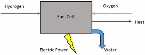
The main function of the PEM fuel cell is to convert chemical energy into electrical energy, and its general schematic is shown in Figure 1.
Figure 1. General schematic of PEM fuel cell
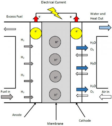
During this conversion, normal water and heat are generated. The various parts of the fuel cell, including the anode, cathode, and membrane, are shown in Figure 2. As it turns out, oxidation occurs through the following reaction inside it
$2 H_{2} \Rightarrow 4 H^{+}+4 e^{-}$ (1)
The released $H^{+}$ions pass through the membrane, while the $e^{-}$ions are not able to pass through it. The following reduction reaction also takes place inside the cathode.
$\mathrm{O}_{2}+4 \mathrm{H}^{+}+4 e^{-} \Rightarrow 2 \mathrm{H}_{2} \mathrm{O}$ (2)
It should be noted that in reaction (2), the oxygen entering the cathode reacts with $H^{+}$passing through the membrane and $e^{-}$transferred to the cathode surface through the external load. The total reaction that occurs is as follows:
$2 \mathrm{H}_{2}+\mathrm{O}_{2} \Longrightarrow 2 \mathrm{H}_{2} \mathrm{O}+$ electrical energy (3)
$V F c=E C e l l-\eta a c t-\eta o h m-\eta c o n$ (4)
Vstack=Ncell. VFc=Ncell.(Ecell-$\eta act$-$\eta ohm$-$\eta con$) (5)
The output voltage of single fuel cell $\left(V_{F c}\right)$ and stack fuel cell $\left(V_{\text {stack }}\right)$ are
In the above relations, $E_{\text {Cell }}$ is the electrochemical thermodynamics potential of the PEM fuel cell and it addresses the best yield voltage, $\eta_{\text {act }}$ is activation polarization loss and specifies the voltage drop because of the activation of the anode and the cathode, $\eta_{o h m}$ is ohmic polarization loss which derived from membrane resistance to move protons and from electrical resistance of the electrodes to move electrons, $\eta_{\text {con }}$ is concentration polarization loss results from the drop in concentration of the reactants, oxygen and hydrogen, which changes during the reaction and $N_{\text {cell }}$ is the number of fuel cell in stack.
2.2 PEM Fuel Cell Dynamic Model
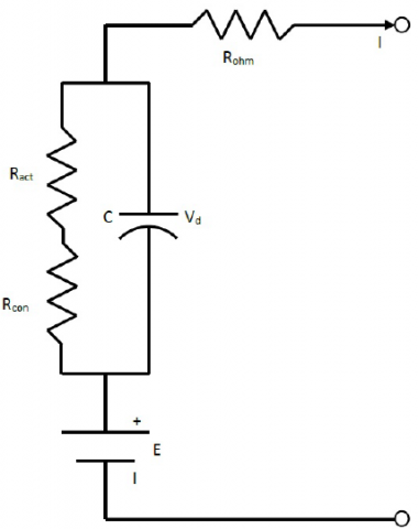
The dynamic model of PEM fuel cell is described in this section. Because the membrane is located in the middle of two charged layers in the PEM cell, it actually acts as a capacitor. Considering Rohm, Ract, Rcon as ohmic, activation and the concentration resistances, the equivalent circuit is shown as in Figure 3.
By writing the Kirchhoffs Voltage Law (KVL) and Kirchhoffs Current Law (KCL) for the equivalent circuit, it is obtained
$V_{\text {cell }}=E_{c e l l}-V_{d}-I R_{o h m}$ (6)
$I=C \frac{d V_{d}}{d t}+\frac{V_{d}}{R_{\text {con }}+R_{a c t}}$ (7)
Figure 2. Various parts of PEM fuel cell and its operation diagram
Figure 3. The equivalent circuit for PEM fuel cell
Equation (7) can be rewritten as follows:
$\frac{d V_{d}}{d t}=\frac{1}{C} I-\frac{1}{\tau} V_{d}$ (8)
Where $V_{d}$ signifies the voltage across the equivalent capacitor, $C$ is the equivalent capacitance, and $\tau$ is the fuel cell time constant equals to
$\tau=C\left(R_{a c t}+R_{c o n}\right)=C\left(\frac{\eta_{a c t}+\eta_{c o n}}{I}\right)$ (9)
It is obtained by placing equations (9) and (8) in equation (6) and taking the Laplace transform.
$V_{\text {cell }}=E_{\text {cell }}-\left(\frac{R_{a c t}+R_{\text {con }}}{\left(R_{\text {act }}+R_{\text {con }}\right) C . s+1}\right.\left.+R_{o h m}\right) I$ (10)
If we want to describe the PEM behavior more accurately, it is necessary to include the pressure of hydrogen and oxygen gases as well as their flow rate in the dynamic model. According to [19-20], the partial pressure equations for oxygen and hydrogen are as follows:
$P_{H_{2}}=\frac{1 / K_{H_{2}}}{\left(1+\tau_{H_{2}}\right)}\left(q_{H_{2}}-2 I \cdot K_{r}\right) 2 H_{2}\Longrightarrow 4 H^{+}+4 e^{-}$ (11)
$P_{O_{2}}=\frac{1 / K_{O_{2}}}{\left(1+\tau_{O_{2}}\right)}\left(q_{o_{2}}-I \cdot K_{r}\right)$ (12)
Where:
$\left\{\begin{array}{l}\tau_{H_{2}}=\frac{V_{a n}}{R \cdot T \cdot K_{H_{2}}} \\ \tau_{O_{2}}=\frac{V_{a n}}{R \cdot T \cdot K_{O_{2}}}\end{array}\right.$ (13)
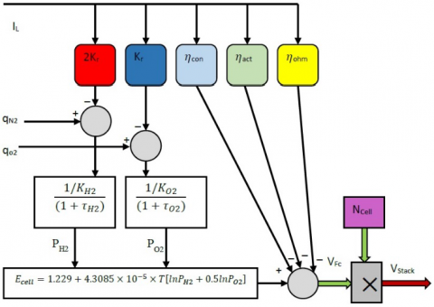
$K_{H_{2}}$ states the valve molar constant for hydrogen $(\mathrm{kmol} / \mathrm{s}$ atm), $\mathrm{Ko}_{2}$ signifies the valve molar constant of oxygen (kmol/ s atm), $q_{H}$ indicates the hydrogen flow rate, $q o_{2}$ specifies the oxygen flow rate, $\tau_{H2}$ shows the response time of hydrogen (s), ${ }^{\tau} o_{2}$ indicates the response time of oxygen (s), $K_{r}$ indicates a modeling parameter constant $(\mathrm{kmol} /(s A))$, and $V_{a n}$ states the volume of the anode. By using the equations, the PEM fuel cell system can be presented as Figure 4.
Figure 4. The PEM fuel cell system dynamic model
2.3 State Space Equations of DC/DC Boost Converters
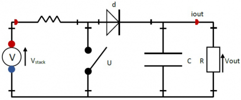
The $\mathrm{DC} / \mathrm{DC}$ boost converter delivers the input voltage from the PEM fuel cell to the output at a higher level, and its schematic is shown in Figure $5 .$
Figure 5. The schematic of boost converter circuit
This converter includes a DC or PEM voltage source, an inductance, a transistor switch, a diode switch, a filter capacitor, and an ohmic load. Through the $u$ switch, the output is set to the following relation
$V_{o u t}=\left(\frac{1}{1-u}\right) \cdot V_{s t a c k}$ (14)
This boost converter works in two modes, the first mode when $u$ is on and $d$ is off, and in this case the dynamic equations governing the inductance current and output voltage are as follows:
$\left\{\begin{array}{l}\frac{d i_{L}}{d t}=\frac{1}{L}\left(V_{\text {stack }}\right) \\ \frac{d V_{\text {out }}}{d t}=\frac{1}{C}\left(-i_{\text {out }}\right)\end{array}\right.$ (15)
In the second operating mode, $u$ is off and $d$ is on, and the dynamic equations of inductance current and output voltage are as follows:
$\left\{\begin{array}{l}\frac{d i_{L}}{d t}=\frac{1}{L}\left(V_{s t a c k}-V_{o u t}\right) \\ \frac{d V_{o u t}}{d t}=\frac{1}{C}\left(i_{L}-i_{o u t}\right)\end{array}\right.$ (16)
Considering the inductance current and output voltage as state variables along with $V_{\text {stack }}=v$, the state space equations for the boost converter are as follows:
$\left\{\begin{array}{c}\dot{x}=\left(\begin{array}{cc}0 & \frac{u-1}{L} \\ \frac{1-u}{C} & -\frac{1}{R C}\end{array}\right) x+\left[\begin{array}{l}\frac{1}{L} \\ 0\end{array}\right] v \\ y=\left[\begin{array}{ll}0 & 1\end{array}\right] x\end{array}\right.$ (17)
The parameters of PEM fuel cell are given in Table 1 . For more information about the model, the reader can refer to [19-23].
Table 1. The parameters of PEM fuel cell
|
Symbol |
Value |
Unit |
|
E0 |
1.229 |
v |
|
R |
83.143 |
$J m o l^{-1} K^{-1}$ |
|
F |
96485.309 |
C $\mathrm{mol}^{-1}$ |
|
T |
298.15 |
K |
|
A |
162 |
c |
|
$\psi$ |
23 |
|
|
l |
$175.10^{-6}$ |
cm |
|
B |
0.1 |
v |
|
$R_{c}$ |
0.0003 |
|
|
$J_{\max }$ |
0.062 |
$A \mathrm{~cm}^{-1}$ |
|
$N_{\text {cell }}$ |
10 |
|
|
$\xi_{1}$ |
0.9514 |
v |
|
$\xi_{2}$ |
−0.00312 |
V/K |
|
$\xi_{3}$ |
−7.4.10−5 |
V/K |
|
$\xi_{4}$ |
1.87.10−4 |
V/K |
The proposed control method is described in this section. In the design of the controller, several issues have been considered that have already been sterilized by previous studies. 1- Due to the non-minimum phase nature of the DC/DC boost converter, direct control methods are not able to properly control and extract the maximum power from the DC source. This feature of the converter leads to controller error and system instability. 2- Like any other physical system, existence of uncertainty in the system model is inevitable. These uncertainties occur in different parts of the system, and sometimes the upper bound of them is not clear. Therefore, it is necessary to consider these uncertainties in the design of the controller.
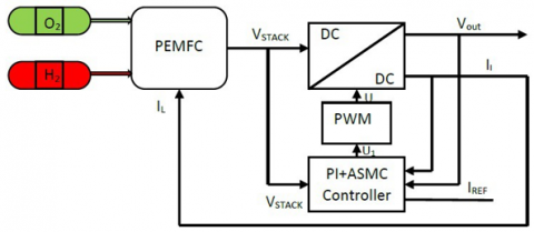
To overcome the adverse effects mentioned above, this paper presents a new hybrid control method based on PI, adaptive and sliding mode techniques. To achieve zero steady state error and extract the maximum power from the fuel cell, the sliding surface is selected through the obtained error after applying the PI method. This approach ensures zero error on the inductance current and consequently maximum power extraction. Using the adaptive approach, the upper bound of uncertainties is estimated and the stability of the system under uncertainties is guaranteed. The controller structure is shown in Figure 6.
Figure 6. The controller structure for PEM fuel cell power system
This controller, taking into account $V_{\text {stack, }} i_{r e f}, i_{L}$ and $V_{\text {out }}$, performs the necessary control over the boost converter and obtains the desired $i_{L}$ and $V_{\text {out }}$. We now describe the controller design process.
By applying the PI method, the dynamic state of the output voltage is defined as follows
$V_{\text {ref }}=k_{P}\left(x_{1}-i_{r e f}\right)+k_{I} \int\left(x_{1}-i_{r e f}\right) d t$ (18)
Where $k_{P}$ and $k_{I}$ are the controller gains and the controller state variables are defined as
$z_{1}=x_{1}-i_{r e f}$
$z_{2}=x_{2}-V_{r e f}$ (19)
According to Equation (17), the dynamics of the state variables are
$\dot{z}_{1}=\frac{1}{L}\left(V-x_{2}\right)+\frac{1}{L} u$
$\dot{z}_{2}=\frac{1}{C} x_{1}-\frac{1}{R_{C}} x_{2}-\frac{k_{P}}{L}\left(V-x_{2}\right)$
$-k_{I}\left(x_{1}-i_{r e f}\right)$
$-\left(\frac{1}{C}+\frac{k_{P}}{L}\right) u$ (20)
And the sliding switching surface is selected as
$S(z)=k_{P}\left(x_{1}-i_{r e f}\right)+k_{I} \int\left(x_{1}-i_{r e f}\right) d t$ (21)
In order to achieve the control goal using the adaptive sliding mode method, it is necessary that the following condition is met for the sliding surface
$\frac{d S}{d t}=0$ (22)
By inserting Equation (20), Equation (22) becomes as
$\dot{S}=k_{P}\left(\frac{1}{L}\left(V-x_{2}\right)+\frac{1}{L} u\right)+k_{I}\left(x_{1}-i_{r e f}\right)=w(x, v, u)+u$ (23)
Where
$w(x, v, u)=k_{I}\left(x_{1}-i_{r e f}\right)+\frac{k_{P}}{L}\left(V-x_{2}\right)+\frac{k_{P}-L}{L} u$ (24)
Lyapunov method is used to ensure stability and find the appropriate control signal to achieve the control goals. Lyapanov's candidate function is selected as equation (25)
$V=\frac{1}{2} S^{2}+\frac{1}{2 \lambda} \tilde{W}^{2}$ (25)
Where $\lambda$ is the parameter of adaptive rule regulation. Also $\hat{W}$ is the error between $W$ and $\hat{W}$
$|w(x, v, u)|<W$ (26)
Where $W$ is the unknown upper bound of $w(x, v, u)$ and $\hat{W}$ is the upper bound estimation. Derived from the Lyapanov function (25) gives
$\dot{V}=S \dot{S}-\frac{1}{\lambda} \tilde{W} \dot{\hat{W}}$ (27)
It is now obtained by placing equation (23) in equation (27)
$\dot{V}=S(w(x, v, u)+u)-\frac{1}{\lambda} \tilde{W} \dot{\hat{W}}$ (28)
Now select the control input as follows:
$u=-k \operatorname{sign}(S)-\widehat{W}$ (29)
It is now obtained by placing (29) in equation (28)
$\dot{V}=-k S \operatorname{sign}(S)+S(w(x, v, u)+\widehat{W})-\frac{1}{\lambda} \widetilde{W} \dot{\hat{W}}$ (30)
According to Equation (40), Equation (44) can be rewritten as follows
$\dot{V} \leq-k|S|+S(W-\widehat{W})-\frac{1}{\lambda} \widetilde{W} \dot{\widehat{W}}$ (31)
To obtain the adaptive law, we rewrite Equation (31) as follows
$\dot{V} \leq-k|S|+\widetilde{W}\left(S-\frac{1}{\lambda} \dot{\widehat{W}}\right)$ (32)
According to $(32)$, in order to eliminate the adaptive error $\hat{W}$, its coefficient must be zero. For this purpose, the adaptive law is obtained as follows
$\dot{\widehat{W}}=\lambda S$ (33)
It is obtained by placing equation (33) in (32)
$\dot{V} \leq-k|S|$ (34)
Equation (34) shows that under the control signal of Equation (29) and using the adaptive law (33), the closed-loop system is stable and the achievement of control objectives is guaranteed. In the next section, simulation in MATLAB environment will be used to show the controller capability.
The purpose of this section is to apply the proposed control method to the system consisting of PEM fuel cell and DC/DC boost converter and evaluate its performance in MATLAB simulation environment. The following hardware has been used for this purpose; Intel Core i7-10750H, 16GB DDR4 RAM, 512GB SSD, NVIDIA GeForce RTX 2060 6GB GDDR6. Also, for better analysis, the obtained results are compared with the outcomes from the implementation of super-twisting algorithm (STA) and SMC methods from reference [24]. The parameters related to PEM fuel cell components, number of cells in the stack structure, membrane cross section, operating temperature of the stack, working pressure of the PEM cell, converter specifications and reference current are all taken from the [24].
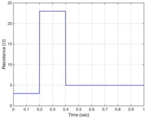
As previously mentioned, the purpose of applying the controller is to extract the maximum possible power from the PEM fuel cell despite the non-minimum-phase nature of the DC/DC boost converter and also the presence of load uncertainty. For this purpose, drastic load changes according to Figure 7 are considered in the simulation scenario. Also, according to the findingsof [24], the controller must track the current il=9.74 A for optimal performance, the current at which the maximum power extraction occurs. We now describe the results obtained from the simulation in MATLAB environment given in Figures 8-13.
Figure 7. Load changes in the simulation scenario
Figure 8 shows the output voltage of the proposed PI-ASMC, SMC and STA controllers. Under load changes and with different control methods, the voltage of a PEM cell and a PEM stack are shown in Figures 9 and 10.
Figure 8. The output voltage of PI-ASMC, SMC and STA controllers
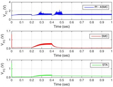
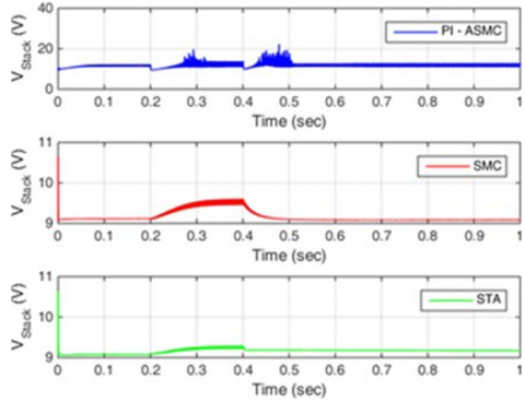
Figure 9. PEM fuel cell voltage under PI-ASMC, SMC and STA controllers
Figure 10. PEM fuel cell stack voltage under PI-ASMC, SMC and STA controllers
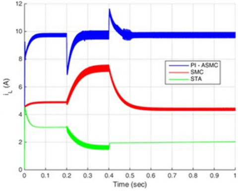
Figure 11. DC/DC boost converter output current under PI-ASMC, SMC and STA controllers
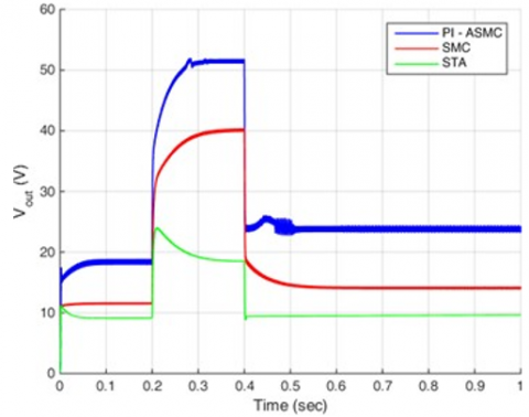
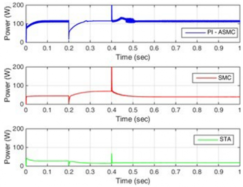
As Figure 11 shows, the most important feature of the proposed method is given here. Through the innovative PI- ASMC method, the reference currenil $i_{l}=9.74$ at is well followed, while other methods, i.e. STA and SMC, due to the nature of the converter as well as the uncertainty effects, are not able to guarantee the desired tracking and system stability. It should also be noted that the existence of the chattering phenomenon in all three control methods used is inevitable and due to the system structure and drastic load changes, all three methods experience the hassle of chattering, overshoot/undershoot and rapid changes in the obtained signal, although only the proposed method is able to track the reference optimal current $i_{l}=9.74$ Afor extracting the maximum power. Figure 12 also shows the output voltage changes of the boost converter by implementing the proposed PI-ASMC, SMC and STA methods. The output voltage changes of the boost converter correspond to the changes in the output load to achieve the maximum power of the converter-fuel cell structure as shown in Figure 13. As Figure 13 shows, despite the rapid changes in the fuel cell output power, the proposed PI-ASMC method is able to deliver the maximum output power from the fuel cell system equipped with a DC/DC boost converter. Despite severe load changes, it achieves the maximum amount of power in the shortest possible time, and its robust and accurate operation is shown in Figure 13. However, STA and SMC methods are not able to deliver the maximum power extractable from the fuel cell system due to their inability to track the optimal current, and in addition, they cannot guarantee the robust and optimal operation of the system.
Figure 12. DC/DC boost converter output voltage under PI-ASMC, SMC and STA controllers
Figure 13. DC/DC boost converter output power under PI- ASMC, SMC and STA controllers
Due to the importance of renewable energy and the need toachieve maximum power from its sources, a new control method was presented for PEM fuel cell system with boost DC/DC converter. The duty of the boost converter is to deliver the appropriate and usable power from the PEM fuel cell source. In this paper, due to the non-minimum phase nature of the converter and also the existence of uncertainties with unknown boundaries in the model, an indirect hybrid control structure based on adaptive, sliding mode and PI techniques was proposed to extract the maximum power. The PI method was used to achieve the zero tracking error, the sliding mode method was used as the robust control method and the adaptive method was used to estimate the upper bound of uncertainties. The simulation results showed that the proposed method, in addition to being able to accurately track the optimal load current, can extract the maximum power from the fuel cell system and also ensure the robust and optimal operation of the system by overcoming the uncertainty effects of the model and the non-minimum phase nature of the DC/DC converter. Future studies will include practical implementation as well as the application of other robust control methods such as backstepping method to overcome the effects of chattering and slow-rate over control signal.
This work was financially supported by the Top Talent Project of Nantong Institute of Technology (XBJRC2021003), Key disciplines of the 14th five year plan in Jiangsu Province: Mechanical Engineering (2022-2), First-class specialty in Jiangsu Province: Mechanical Design, Manufacturing and Automation (2020- 9), Science and Technology Project of Nantong (Grant No. JC2020155), Key Laboratory of Laser Processing and Metal Additive of Provincial Science and Technology Service Platform Cultivation Project of Nantong Institute of Technology (Grant No. XQPT202101)."
[1] Sonter, L. J., Dade, M. C., Watson, J. E., & Valenta, R. K.(2020). Renewable energy production will exacerbatemining threats to biodiversity. Nature communications,11(1), 1-6.
[2] Elavarasan, R. M., Shafiullah, G. M., Padmanaban, S.,Kumar, N. M., Annam, A., Vetrichelvan, A. M., ... &Holm-Nielsen, J. B. (2020). A comprehensive review onrenewable energy development, challenges, and policiesof leading Indian states with an international perspective.IEEE Access, 8, 74432-74457.
[3] Vakulchuk, R., Overland, I., & Scholten, D. (2020).Renewable energy and geopolitics: A review. Renewableand Sustainable Energy Reviews, 122, 109547.
[4] Saidi, K., & Omri, A. (2020). The impact of renewableenergy on carbon emissions and economic growth in 15major renewable energy-consuming countries.Environmental research, 186, 109567.
[5] Mekhilef, S., Saidur, R., & Safari, A. (2012). Comparative study of different fuel cell technologies. Renewable andSustainable Energy Reviews, 16(1), 981-989.
[6] Luo, F. L., & Ye, H. (2016). Advanced dc/dc converters.crc Press.
[7] Emadi, A., & Ehsani, M. (2000, July). Negativeimpedance stabilizing controls for PWM DC-DCconverters using feedback linearization techniques. InCollection of Technical Papers. 35th Intersociety EnergyConversion Engineering Conference and Exhibit
(IECEC)(Cat. No. 00CH37022) (Vol. 1, pp. 613-620). IEEE.
[8] Farivar, G., Agelidis, V. G., & Hredzak, B. (2014, March). Fuzzy logic based control system for cascaded H-bridgeconverter. In 2014 IEEE Applied Power ElectronicsConference and Exposition-APEC 2014 (pp. 3006-3010).IEEE.
[9] Balezentiene, L., Streimikiene, D., & Balezentis, T.(2013). Fuzzy decision support methodology forsustainable energy crop selection. Renewable andSustainable Energy Reviews, 17, 83-93.
[10] Tan, S. C., Lai, Y. M., & Tse, C. K. (2006). A unifiedapproach to the design of PWM- based sliding-modevoltage controllers for basic DC-DC converters incontinuous conduction mode. IEEE Transactions onCircuits and Systems I: Regular Papers, 53(8), 1816-1827.
[11] Tan, S. C., Lai, Y. M., & Chi, K. T. (2006, June). Anevaluation of the practicality of sliding mode controllersin DC-DC converters and their general design issues. In2006 37th IEEE Power Electronics Specialists Conference (pp. 1-7). IEEE.
[12] He, Y., & Luo, F. L. (2006). Design and analysis ofadaptive sliding-mode-like controller for DC-DCconverters. IEE Proceedings-Electric Power Applications,153(3), 401-410.
[13] Alqahtani, A. H., & Utkin, V. I. (2012, October). Self-optimization of photovoltaic system power generationbased on sliding mode control. In IECON 2012-38thAnnual Conference on IEEE Industrial ElectronicsSociety (pp. 3468-3474). IEEE.
[14] Tan, S. C., Lai, Y. M., Tse, C. K., & Cheung, M. K. (2004, February). An adaptive sliding mode controller for buckconverter in continuous conduction mode. In NineteenthAnnualIEEE Applied Power Electronics Conference andExposition, 2004. APEC'04. (Vol.3, pp.1395-1400) IEEE.
[15] Tan, S. C., Lai, Y. M., Cheung, M. K., & Tse, C. K.(2005). On the practical design of a sliding mode voltagecontrolled buck converter. IEEE transactions on powerelectronics, 20(2), 425-437.
[16] Tan, S. C., Lai, Y. M., Tse, C. K., & Cheung, M. K.(2006). Adaptive feedforward and feedback controlschemes for sliding mode controlled power converters.IEEE Transactions on Power Electronics, 21(1), 182-192.
[17] Cid-Pastor, A., Martinez-Salamero, L., El Aroudi, A.,Giral, R., Calvente, J., & Leyva, R. (2013). Synthesis ofloss-free resistors based on sliding-mode control and itsapplications in power processing. Control EngineeringPractice, 21(5), 689-699.
[18] López-Lapeña, O., Penella, M. T., & Gasulla, M. (2009).A new MPPT method for low- power solar energyharvesting. IEEE Transactions on industrial electronics,57(9), 3129- 3138.
[19] Padulles, J., Ault, G. W., & McDonald, J. R. (2000). Anintegrated SOFC plant dynamic model for power systemssimulation. Journal of Power sources, 86(1-2), 495-500.
[20] Uzunoglu, M., & Alam, M. S. (2006). Dynamic modeling,design, and simulation of a combined PEM fuel cell andultracapacitor system for stand-alone residential applications. IEEE Transactions on Energy Conversion, 21(3), 767-775.
[21] Mohan, N., Undeland, T. M., & Robbins, W. P. (2003).Power electronics: converters, applications, and design.John wiley & sons.
[22] Wang, C., Nehrir, M. H., & Shaw, S. R. (2005). Dynamicmodels and model validation for PEM fuel cells usingelectrical circuits. IEEE transactions on energyconversion, 20(2), 442-451.
[23] Larminie, J., Dicks, A., & McDonald, M. S. (2003). Fuelcell systems explained (Vol. 2, pp. 207-225). Chichester,UK: J. Wiley.
[24] Derbeli, M., Farhat, M., Barambones, O., & Sbita, L.(2017). Control of PEM fuel cell power system usingsliding mode and super-twisting algorithms. Internationaljournal of hydrogen energy, 42(13), 8833-8844.