Y. RavindranathTagore* | A. R. Vijay Babu | Y. Srinivasarao | P. Manoj Kumar | K. Anuradha
© 2021 IIETA. This article is published by IIETA and is licensed under the CC BY 4.0 license (http://creativecommons.org/licenses/by/4.0/).
OPEN ACCESS
This paper presents the air breathing fuel cell (ABFC) power system and its investigation for industrial applications. The ABFC actual behaviour is realized through the development of an empirical model by considering activation polarisation, ohmic polarisation and mass transport effects. The developed stack model feeds the power conditioning unit of the proposed power system. This paper will throw light on the usage of GaN wide bandgap (WBG) material based power semiconductor devices (PSDs) that are used to build 5-level cascaded H- bridge multilevel inverter and a boost converter. This in turn enhances the energy efficiency of the entire FC power system. These WBG PSDs present the phenomenal properties such as high saturated drift velocity, wide bandgap and high critical breakdown field. This multilevel inverter is implemented for facilitating a quality AC output besides offering the voltage control. The investigation is carried out with the development of power conditioning unit hardware setup besides the fabricated FC module for the validation the developed ABFC model.
A fuel cell is an electrochemical device that utilizes hydrogen and oxygen to generate electrical power, the by-products are water and heat. The fuel cell [FC] generates power as long as the fuel is supplied. In fuel cells, there is no combustion process and operates silently [1]. The fuel cells can realize the integration of renewables into electricity systems. The fuel cells present the following advantages.
• High efficiency
• High reliability
• Scalability and flexible siting
• Durability
• Modularity
The anode and cathode reactions of FC are given by Eqs. (1)-(3).
$2 \mathrm{H}_{2} \rightarrow 4 \mathrm{H}^{+}+4 \mathrm{e}^{-}$ (1)
$\mathrm{O}_{2}+4 \mathrm{H}^{+}+4 \mathrm{e}^{-} \rightarrow 2 \mathrm{H}_{2} \mathrm{O}$ (2)
Overall reaction: $2 \mathrm{H}_{2}+\mathrm{O}_{2} \rightarrow 2 \mathrm{H}_{2} \mathrm{O}+$ Electricity $+$ Heat (3)
ABFC does not utilize auxiliary fan as required in other fuel cells realized with forced convection and results in reduced weight and volume of system, and hence pertinent for their commercialization in industrial applications. A single FC produces an output voltage of 0.5 V to 0.7 V at the specified operating conditions [2]. Moreover, the FC performance highly relies on temperature, humidification, flow rate, pressure, and also reactant feed to the FC including the load dynamics. Nowadays, the required fuel cell power lies in the range of few kW to MW. To get desired power and voltage levels, a series connection of several FCs is realized by forming a fuel cell stack. Many times, step-up converters are used for boosting the FC stack voltage. Importantly, the DC-DC and DC-AC power conditioning unit (PCU) plays a key role for enhancing the lifetime of the FCs. The WBG semiconductor materials exhibit the phenomenal properties such as high saturated drift velocity, wide bandgap and high critical breakdown field. These properties have led to the development of promising SiC and GaN based PCUs for improving the energy efficiency of the entire FC power system [3]. The selection of PCU along with proper closed loop control attains the robustness of a FC against the current ripples. The allowable FC current ripples are strictly less than 5% of the rated current. The 1-Ø or unbalanced 3-Ø ac loads generates a large second harmonic ripple current in the inverter dc link. It is important to filter these harmonics before their transfer from the dc bus to the FC stack. Furthermore, the multilevel converters are attractive in renewable energy supported applications such as industrial drives, distributed generation and power quality. The DC-AC converters play a prominent role while interfacing the FCs to the grid especially in case of a distributed generation [4]-[7]. This paper presents the modeling and experimental validation of an ABFC power system for industrial applications. The investigation is carried out with the development of GaN based PCU hardware setup along with a fabricated FC module for validating the developed ABFC model. Section 2 and Section 3 present the proposed power system and modeling aspects with validation, whereas Section 4, Section 5 and Section 6 explore the PCU design, experimental results and conclusions.
The different blocks of the proposed power system are as follows:
• ABFC stack MATLAB/Simulink model.
• GaN based DC-DC and DC-AC converters.
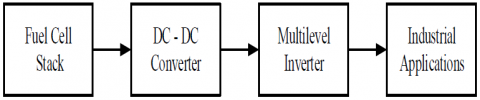
Figure 1 highlights the schematic of the proposed power system.
Figure 1. Block diagram of the overall ABFC power system
3.1 Implementation of stack model
The hydrogen/oxygen FC has the standard potential of 1.229 V at STP (25oC and 1atm). However, the deviation from the equilibrium potential is due to ohmic, activation and concentration losses. Eqs. (4)-(10) realize the ABFC output voltage [2], [8].
$\mathrm{V}_{\text {Fuelell }}=\mathrm{V}_{\text {Opencircuit }}-\Delta \mathrm{V}_{\text {Activation }}-\Delta \mathrm{V}_{\text {Ohmic }}-\Delta \mathrm{V}_{\text {Concentration }}$ (4)
$\mathrm{V}_{\text {Opencircuit }}=\mathrm{V}_{\text {Nernst }}-\mathrm{V}_{\text {Crossover }}$ (5)
$\mathrm{V}_{\text {Nermst }}=-0.000845 * \mathrm{~T}+1.482+0.0000431 * \mathrm{~T} * \ln \left(\rho_{\mathrm{H}_{2}} * \rho_{\mathrm{O}_{2}}{ }^{0.5}\right)$ (6)
$\mathrm{V}_{\text {Crossover }}=\frac{\mathrm{TR}}{\mathrm{F} \alpha} \ln \left(\frac{\mathrm{i}_{\text {Crossover }}}{\mathrm{i}_{0}} \quad \right)$ (7)
$\rho_{\mathrm{H}_{2}}=\frac{0.5 \mathrm{P}_{\mathrm{H}_{2}}}{\exp \left(\frac{1.653 * \mathrm{i}}{\mathrm{T}_{\mathrm{ADP}}^{1.334}} \quad \right)}-\mathrm{P}_{\mathrm{Sat}}$ (8)
$\rho_{\mathrm{O}_{2}}=\frac{\mathrm{P}_{\mathrm{O}_{2}}}{\exp \left(\frac{4.192 * \mathrm{i}}{\mathrm{T}_{\mathrm{GDP}}^{1.334}} \quad \right)}-\mathrm{P}_{\mathrm{Sat}}$ (9)
$\mathrm{P}_{\text {Sat }}=10^{\left(-9.1837* 10^{-5} * \mathrm{~T}^{2}-2.1794+0.02953* \mathrm{~T}+1.4454*10^{-7} * \mathrm{~T}^{2}\right)}$ (10)
Where F, R, V, PSat, p and P are the Faraday’s constant (C/mol), Gaseous constant (J/mol.K), cell voltage (V), saturation pressure of water, partial pressure and pressure of hydrogen in bar. The activation loss is modelled according to Eq. (11).
$\Delta \mathrm{V}_{\text {Activation }}=\frac{\mathrm{RT}}{\alpha \mathrm{F}} \ln \left(\frac{\mathrm{i}}{\mathrm{i}_{0}}\right)$ (11)
By considering the internal losses in Eq. (12), the activation losses are:
$\Delta \mathrm{V}_{\text {Activation }}=\frac{\mathrm{RT}}{\alpha \mathrm{F}} \ln \left(\frac{\mathrm{i}+\mathrm{i}_{\mathrm{cr}}}{\mathrm{i}_{0}}\right)$ (12)
Eqs. (13)-(18) present the ABFC ohmic loss.
$\Delta \mathrm{V}_{\text {Ohmic }}=\mathrm{i}* \mathrm{r}_{\text {Ohmic }}$ (13)
$\mathrm{r}_{\text {Ohmic }}=\mathrm{r}_{\text {Anode }(\mathrm{A})} \quad+\mathrm{r}_{\text {Cathode }(\mathrm{C})} \quad+\mathrm{r}_{\mathrm{Ionic}}+\mathrm{r}_{\text {Contact }}$ (14)
$\mathrm{r}_{\mathrm{A}}=\frac{\rho_{\text {GasDiffusionLayer }(\mathrm{GDL}) * \mathrm{~L}_{\mathrm{GDL}}}}{\mathrm{A}_{\text {Cell }}} \quad + \quad \frac{\rho_{\text {Graphite}* \mathrm{~L}_{\text {Graphite}}}}{\mathrm{A}_{\text {Cell }}}$ (15)
$\mathrm{r}_{\mathrm{C}}=\frac{\rho_{\text {GasDiffusionLayer }(\mathrm{GDL}) * \mathrm{~L}}}{A_{\text {Cell }}} \quad + \quad \frac{\rho_{\text {Graphite }* \mathrm{~L}}}{A_{\text {Cell }}}$ (16)
$r_{\text {Ionic }}=\frac{L_{\text {Membrane }}}{\sigma A_{c}}$ (17)
$\sigma=(-0.00326+0.005169 * \lambda) * \exp \left(\left(-\frac{1}{\mathrm{~T}}+\frac{1}{303}\right) 1268\right)$ (18)
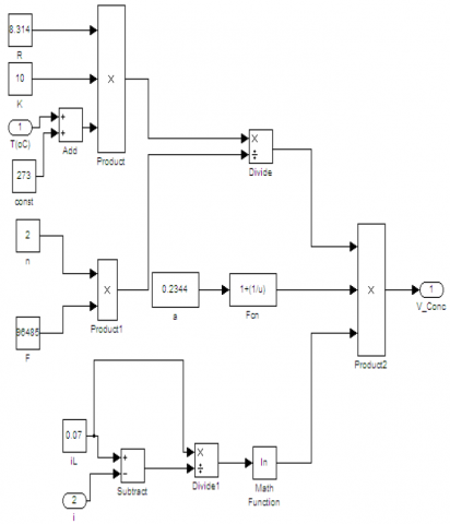
$\Delta \mathrm{V}_{\text {Concentrat }}=\frac{\mathrm{TR}}{\mathrm{Fn}}\left(\frac{1}{\alpha}+1\right) \ln \left(\frac{\mathrm{i}_{\mathrm{L}}}{-\mathrm{i}+\mathrm{i}_{\mathrm{L}}}\right)$ (19)
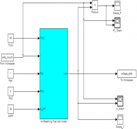
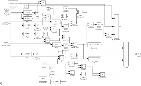
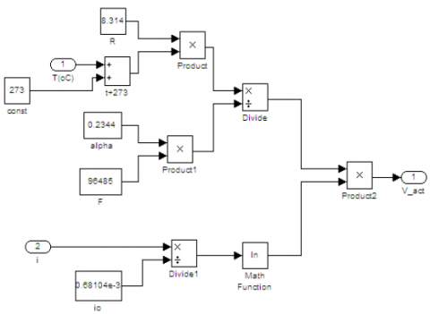
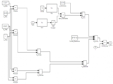
Where ΔV, AC, L, r, ρ, i and T are the overpotential (volts), cell area (cm2), membrane thickness (cm), ohmic resistance (Ω-cm2), specific resistance (Ω-cm), current density (mA/cm2) and cell temperature (K). GDL means gas diffusion layer. Figure 2 presents the development of MATLAB/Simulink model of an ABFC based on Eqs. (4)-(19). Figure 3 to Figure 6 shows the sub blocks of the MATLAB/Simulink model highlighting the various losses of the FC. Table 1 shows the simulation parameters taken from the data sheets of respective manufacturers and also literature [2], [8]. $\alpha$, $\sigma$ and λ are the charge transfer coefficient, conductivity of membrane (S/cm) and water drag coefficient.
Table 1. FC nominal specifications
|
Specification |
Value |
|
ρ of GDL |
0.0017 Ω-Cm |
|
Thickness of GDL |
0.036 Cm |
|
ρ of Graphite |
0.00231 Ω-Cm |
|
Thickness of Graphite Flow Channel |
0.1 Cm |
|
LMembrane |
0.0178 Cm |
|
λ |
12 |
|
icr |
3 mA/Cm2 |
|
Contact Resistance |
30 Ω-Cm2 |
Figure 2. The MATLAB/Simulink model of the fuel cell stack
Figure 3. ABFC MATLAB/Simulink model for Open Circuit Voltage
Figure 4. MATLAB/Simulink model for Activation Loss of an ABFC
Figure 5. ABFC MATLAB/Simulink model for Ohmic Loss
Figure 6. MATLAB/Simulink model for Concentration Loss of an ABFC
3.2 Implementation of stack model
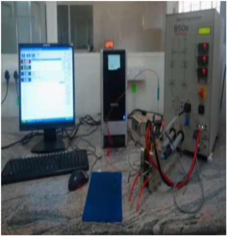
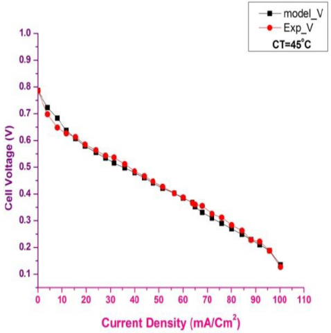
The fabrication consists of 5 cm2 active area FC membrane electrode assembly (MEA), having 1mg/cm2 Pt/C (40%) catalyst loading, and hydrophobisation at anode and cathode with electrolyte membrane of Nafion - 117. Table 2 shows the experimental exchange current density (io) and charge transfer coefficient (α) values. Figure 7 shows 850e FC test setup and the measured polarisation characteristic of the FC are shown in Figure 8. Figure 9 highlights the validation of simulated FC voltage characteristics with that of experimentally measured values at 45oC. A good match is observed between the attained characteristics.
Table 2. ABFC electro chemical parameters
|
|
α |
IO |
|
25oC |
0.974 |
0.973 mA/cm2 |
|
45oC |
0.638 |
1.6812 mA/cm2 |
Figure 7. Fuel cell test System
Figure 8. ABFC Polarisation characteristic
Figure 9. ABFC Validation at 45oC
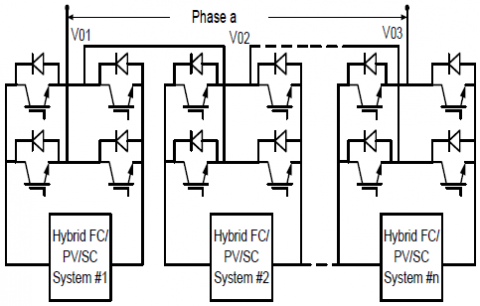
Recently, power conversion using multilevel inverters is fulfilled for electric utility and drives applications [9]-[11]. These converters are suitable to visualize a near sinusoidal voltage from different DC power sources such as solar PV cells, hydrogen energy, batteries and ultra-capacitors. The total harmonic distortion depends on the output voltage levels. Nowadays, there exits the three commercial multilevel converters namely diode clamped, cascaded H-bridge (HB) and flying capacitor multilevel inverter (MLI) topologies. The flying capacitor MLIs are effective in high band-width and high switching frequency applications. The cascaded H-bridge type is used in reactive power compensation, uninterruptable power supplies etc. The diode clamped MLIs are designed for conveyors, fans, pumps and back-to-back applications. However, the cascaded HB MLI is widely used as it needs less number of components, eliminates the need of a bulky capacitor and reduced size compared to the other MLIs. But, based on the level, they need more number of isolated voltage sources. The schematic diagram of a GaN cascaded HB MLI is depicted in Figure 10.
Figure 10. Schematic diagram of cascaded HB MLI
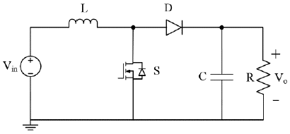
This paper highlights the application of a carrier based alternative phase disposition (APOD) sinusoidal pulse width modulation (SPWM) technique for voltage control as well minimizing the harmonics. For N levels, (N – 1) carrier waveforms exists, and each carrier is out of phase with its accompanying carrier by 180°. The input dc voltage for the cascaded HB MLI comes from a FC stack via boost converter. The GaN boost converter should have a high voltage gain for boosting the lower stack voltage. Figure 11 shows the schematic of a wide voltage-gain boost converter with voltage conversion ratio given by Eq. (20).
$\frac{\mathrm{V}_{\text {Out }}}{\mathrm{V}_{\text {In }}}=\frac{1}{1-\mathrm{D}}$ (20)
Figure 11. Schematic diagram of a GaN DC-DC boost converter
Table 3 shows the boost converter and GaN multilevel inverter design specifications.
Table 3. Boost converter and multilevel inverter design specifications
|
Parameter |
Value |
|
GaN Boost Converter |
|
|
Fuel cell stack voltage (or) Boost converter input voltage |
30 ~ 45 V |
|
Output voltage |
230 V |
|
Inductor (L) |
200 µH |
|
Capacitors (C) |
0.016 µF |
|
Switching frequency |
100 kHz |
|
GaN Cascaded HB MLI |
|
|
DC link voltage |
230 V |
|
Carrier frequency |
2 KHz |
|
Load resistance/phase |
100 Ω |
|
Output power |
200 W |
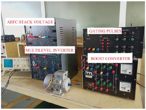
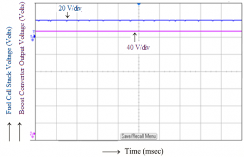
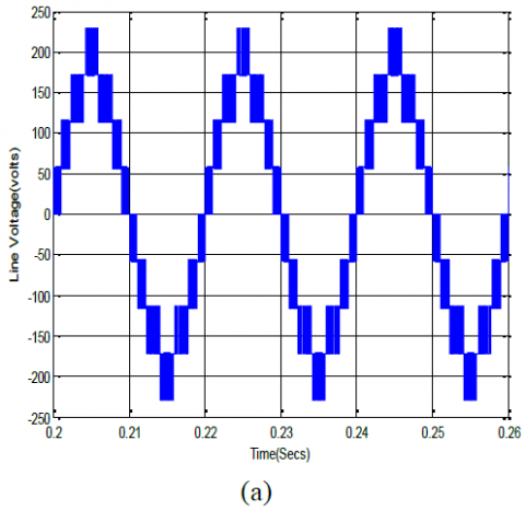
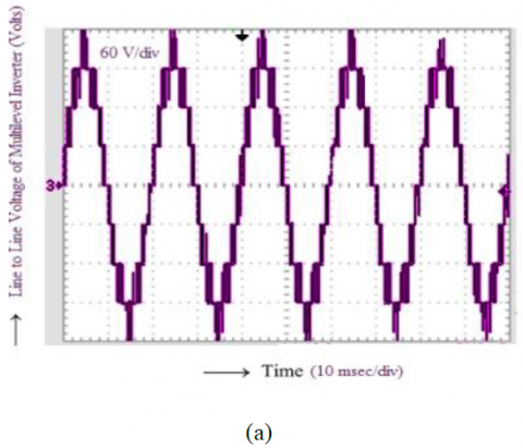
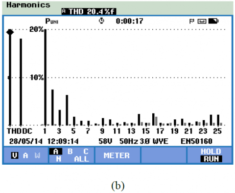
The experiment is performed on a GaN based 5-level cascaded HB MLI which is fed from a boost converter. Figure 12 shows the experiment setup of prototype power conditioning unit along with a 3-Ø resistive load. Figure 13 shows the experimental results for fuel cell stack voltage and also the voltage mode based boost converter output voltage (230 V). The output voltage has a ripple of less than ±5 %. Figure 14 (a) and Figure 15 (a) show the comparison of simulation and experimental results for the line-line output voltage waveform of a 5-level cascaded HB MLI at modulation index of 0.9. The corresponding total harmonic distortion (THD) plots are shown in Figure 14 (b) and Figure 15 (b) with THD values of 18.22% and 20.4%. For getting still lower THD, it is important to increase the output level at the penalty of increased cost of the multilevel inverter. The GaN MLI ensures an efficiency of 98.6% and the boost converter with 97.9%. This aggrandizes the overall efficiency of the ABFC power system.
Figure 12. Experimental setup of the proposed power system
Figure 13. Experimental voltage waveforms of fuel cell stack voltage and boost converter output voltage
Figure 14. Simulation results of a three phase GaN 5-level cascaded HB MLI. a) Line-to-line voltage. b) Line-to-line voltage THD
Figure 15. Experimental results of a three phase GaN 5-level cascaded HB MLI. a) Line-to-line voltage. b) Line-to-line voltage THD
This paper emphasizes the modeling, validation and implementation of an ABFC power system. The developed model has shown a good match with the experimental results. The FC stack feeds the GaN based PCU that comprises of stepup boost converter and 3-Ø 5-level cascaded HB MLI. The experimental results are validated with the simulation results for both the line voltage and THD waveforms. This multilevel inverter is well suited as a part of the PCU for most of the FC powered power system applications. The GaN based PCU ensures an efficiency of more than 96%. This is extremely helpful in enhancing the overall efficiency of the ABFC power system. Here, the proposed power system implementation is limited to low power applications. The research work can be extended further with increased power ratings. Moreover, in distributed generation, a much focus is required on the application of regenerative fuel cells for storing the energy generated by the other important renewable energy sources.
[1] Yadlapalli, R.T., Kotapati, A. (2020). Modeling and Control of Laptop Computer Voltage Regulator Module with Multiple Power Sources. Journal Européen des Systèmes Automatisés, 53(3):421-427.
[2] Ravindranath Tagore, Y., Anuradha, K., Vijay Babu Atluri, R., Manoj kumar, P. (2019). Modelling, Simulation and Control of Fuel cell Powered Laptop Computer Voltage Regulator Module. International Journal of Hydrogen Energy, 44(21):11012-11019.
[3] Garrido-Diez, D., Baraia, I. (2017). Review of wide bandgap materials and their impact in new power devices. 2017 IEEE International Workshop of Electronics, Control, Measurement, Signals and their Application to Mechatronics (ECMSM), Donostia- San Sebastian, 1-6.
[4] Katebi, R., He, J., Weise, N. (2018). An Advanced Three-Level Active Neutral-Point-Clamped Converter With Improved Fault-Tolerant Capabilities. IEEE Transactions on Power Electronics, 33(8):6897-6909.
[5] Fu, Y., Huang, Y., Bai, H., Lu, X., Zou, K., Chen, C. (2018). A High-efficiency SiC Three-Phase Four- Wire inverter with Virtual Resistor Control Strategy Running at V2H mode. 2018 IEEE 6th Workshop on Wide Bandgap Power Devices and Applications (WiPDA), Atlanta, GA, 174-179.
[6] Aguilar Vega, F., Mukherjee, N., Carter, R., Fuerst, J., Diepold, F. (2019). Three-level GaN inverter with SiC diodes for a possible three-phase high power solution. The Journal of Engineering, 2019(17, 6 2019):4461- 4465.
[7] Gurpinar, E, Iannuzzo, F., Yang, Y., Castellazzi, A., Blaabjerg, F. (2018). Design of Low-Inductance Switching Power Cell for GaN HEMT Based Inverter. IEEE Transactions on Industry Applications, 54(2):1592-1601.
[8] Kim, J., M. Lees, M., Srinivasan, S., Charles, E. C. (1995). Modelling of proton exchange membrane fuel cell performance with an empirical equation. J Electrochem Soc., 142(8):2670-74.
[9] Jose, R., Jih-sheng, L., Fang, Z. Multilevel inverter: (2002). A Survey of Topologies, controls and Applications. IEEE Transactions on Industrial Electronics, 49(4):724-38.
[10] Koshti, A.K., Rao, M.N. (2017). A brief review on multilevel inverter topologies. 2017 International Conference on Data Management, Analytics and Innovation (ICDMAI), Pune, 187-193.
[11] Maurya, S., Mishra, D., Singh, K., Mishra, A. K., Pandey, Y. (2019) "An Efficient Technique to reduce Total Harmonics Distortion in Cascaded H- Bridge Multilevel Inverter. 2019 IEEE International Conference on Electrical, Computer and Communication Technologies (ICECCT), Coimbatore, India, 1-5.