Pallavi Chaudhury* | Sikata Samantaray
© 2021 IIETA. This article is published by IIETA and is licensed under the CC BY 4.0 license (http://creativecommons.org/licenses/by/4.0/).
OPEN ACCESS
In this research work the thermal modeling of a nonconductive Silicon carbide Ceramic matrix composite (CMC) machined by Die Sinking Electric Discharge Machining (EDM) has been done. Though SiC is a non-conductive material but the presence of CNT makes it a conductive material which can be machined with EDM. The modeling procedure carried out by considering some realistic approach like Gaussian heat Flux, Specific Discharge Energy, Variable Latent heat etc. For this analysis a 2D continuum has been designed as work domain. By simulating the work domain model by a Finite Element Analysis (FEA) Software (COMSOL), material removal rate (MRR) has been estimated with variable thermal properties. Parametric analysis of effect of Variable Specific heat on MRR by considering different current, Voltage and Pulse-On time has been performed. The effect of different input parameters (peak current and Pulse-on time) on Crater geometry has been done. A new concept of Specific discharge energy has been introduced during modelling to make it a more realistic model which can also be used as electrode support for electrochemical energy devices as Polymer Electrolyte Membrane Fuel Cells on Li-ion battery. Desirability analysis has been done to get an optimize set of input parameters for I= 3A, V=30V, Ton= 75 µs for machining ceramic matrix composite by EDM. The optimized MRR at this setting is 7.25 mm3/min whereas PFE is 87%. The experimental analysis has been also performed to strengthen the thermal and mathematical modelling.
Thermal model, Ceramic matrix composite, Carbon nano tube, Electrical discharge machining, Heat flux, fraction of heat, material removal rate, desirability analysis
Electrical discharge machining (EDM) is a highly effective method for producing complicated moulds and machining hard materials. A voltage is applied between two electrodes, the instrument and the work piece, which are tightly spaced within a liquid dielectric medium. When this voltage is applied, an electric spark discharge occurs between the electrodes, causing enough heat to melt and even vaporise the machined workpiece material. During the discharge phase, a plasma channel forms between the anode and cathode, allowing electrons and ions to pass into it, displace the dielectric fluid, and induce a significant volume of pressure on the work piece surface, preventing the molten substance from flowing. As the spark collapses, the abrupt release of pressure causes a violent ejection of the liquid and vaporised material from the workpiece floor, the gushing of the dielectric to fill the vacuum, and the forming of small craters at material removal sites.
The primary fundamental phenomenon causing material removal in the EDM phase is the electric discharges produced between the tool and the workpiece. The substance removal process is a result of the fusion of two processes (Dibitonto et al. [1];Schumacher [2]; Shuvra Das et al. [3]). The first is thermal in nature, caused by electric discharges that generate high energy densities of approximately 1017 W/m2 (Ekmekci et al. [4]), resulting in the rapid melting and even evaporation of material. The second form is hydrodynamic erosion, which occurs as a result of the gas bubble collapsing and expelling a portion of the molten liquid. Dibitonto et al. [1] quantified this expelled fraction experimentally using a parameter called plasma flushing quality (PFE).
Earlier published works mostly used computational models (Snoeys and Van Dijck [5]; Van Dijck and Dutre [6]; Beck [7, 8]; Jilani and Pandey [9, 10]; Erden and Kaftanoglu [11]; Lhiaubet and Meyer [12]; Lhiaubet et al. [13]; Pandey and Jilani [14]; Dibitonto et al. [1]; Patel et al. [15]). These models allowed prediction of the temperature distribution chart, material removal rate (MRR), and shape of the crater on the machined workpiece. These experiments used a variety of different types of thermal loading. Snoeys and Van Dijck [5], Beck [7], Jilani and Pandey [10] all used a constant-radius disc heat source. Dibitonto et al. [1] simulated cathode erosion using a point heat source and a decreased plasma radius during the discharge. The majority of the authors cited above believe that 50% of heat power (Fc=0.5) is transmitted to the workpiece; only Dibitonto et al. [1] believed it was equivalent to 18.3% at the cathode. In the majority of these experiments, the thermal properties of machined material is assumed to be stable. At the end of the discharge, the crater's morphology and volume is determined using the isothermal curve that separates the liquid and solid portions of the workpiece material. SiC/CNT has an excellent electrical and thermal conductivity due to which it can be used as electrode support for electrochemical energy devices as Polymer Electrolyte Membrane Fuel Cells on Li-ion battery [14,15]. Yeo et al. [16] conducted a thorough analysis and review of prior models, and they were found to be inconsistent with experimental findings. As a conclusion, he demonstrated that the model established by DiBitonto et al. [1] has the strongest agreement with experimental data. Recently published papers (Shuvra Das et al. [3]; Kansal et al. [17]; Marafona and Chousal [18]; Ghanem et al. [19]; Salah, N.B et al. [20, 21]; Bhondwe et al. [22]; Vinod Yadav et al. [23]) have advanced the field of computational simulation of the EDM method. The assumptions of these experiments have been significantly changed. In both of these experiments, the Gaussian form of the heat flux distribution was assumed, as was the temperature-dependent evolution of the thermal properties of machined material. The value of the power fraction transmitted to the workpiece continues to be a source of contention. Shuvra Das et al. [3], Ghanem et al. [19], and Salah et al. [20, 21] recommended an 18% value, while Vinod Yadav et al. [23] recommended an 8% value. Marafona and Chousal [18] assume that the fraction of energy transmitted to the workpiece is 50%. According to Kansal et al. [17] and Bhondwe et al. [22], the powder fraction (Fc) is dependent on the dielectric fluid used.
Many authors have been considered the constant thermal properties for the thermal analysis. Numerical study of Metal matrix composite (MMC) or Ceramic matrix composite has not been significantly performed. Least work has been done to show the Effect of Specific Discharge Energy (SDE) for removing material by EDM. The combined effect of SDE & Latent heat on the material erosion process has not been performed till now. The present work has been focused on the numerical modeling of the SiC (6vol% of CNT) machined by EDM. For this analysis Gaussian heat flux has been taken as heat source. A comparison study of MRR for experimental results and varying thermal properties has been done.
1.1 Introduction to Specific Discharge Energy
A novel technique The specific discharge energy (SDE) of a wire electrical discharge machining process is defined as the actual energy needed to extract a unit volume of a specific material. As shown, current forecasting methods are insufficient to satisfy the needs of EDM processes, and a new approach for predicting EDM efficiency with sufficient precision and cost is warranted. Liao [27] pioneered the idea of specific discharge energy (SDE) in wire-cut electric discharge machining (WEDM) in order to demonstrate the relationship between material properties and EDM efficiency. Liao simplifies the complex interaction between material properties and efficiency by computing the SDE of a variety of materials.
SDE offers a quantitative and straightforward method for describing the properties of materials and assists in effectively estimating the efficiency of different materials. Materials with comparable SDE have been shown to perform similarly under the same conditions, while materials with a lower SDE appear to be extracted more quickly but perform poorly. The theory is validated and applied to the optimization of parameters for various materials in WEDM [28]. However, despite the fact that SDE offers special advantages in wire-EDM, acquiring its worth is difficult. According to Liao's research, not all energy transmitted to the workpiece is used to erode the substance [27]. Thus, an additional L18 mixed orthogonal Taguchi quality design tool must be used to determine the proportion of total energy currently used for metal removal under different circumstances, necessitating an extraordinary amount of work and effectively impeding further implementation of SDE. Indeed, the EDM mechanism can be thought of as a single spark compounded by the discharge frequency. The energy transmitted in the heat influenced region during the previous pulse, which Liao ignores, has a direct effect on the subsequent pulse. But for the energy dissipated in the tens of micrometres deep heat-affected region over the course of an EDM phase, the actual energy needed to extract the substance is the overall energy spread on the surface. To obtain the SDE value more precisely and effectively, this analysis establishes a computational approach based on the simulation model. The equivalent temperature and proportion of energy distribution have been considered concurrently in this analysis. SDE can be defined mathematically as the ratio of material removal energy to material removal volume. Finally, the numerical value of SDE was validated by comparing it to experimental data.
2.1 Experimental SET-UP
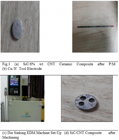
The SMART ZNC Die Sinking EDM machine has been used for machining the SiC/CNT Ceramic matrix Composite. Commercial grade EDM oil (specific gravity 0.763, flash point 94˚C) has been used as dielectric fluid. The Flushing Pressure has been considered at 10Kgf/cm2. In the Present Study SiC Ceramic has been reinforced with 6% Carbon Nano tube Nano particle by Powder Metallurgy Process. The Electrical Conductivity has been reached about 119 S/m which is sufficient to machine the ceramic matrix by EDM.
2.2 Experimental Methodology
In order to study the effects of EDM on Ceramic matrix Material Removal Rate (MRR) has been calculated experimentally. In this present study Peak Current and Pulse On time has been varied by keeping Voltage (30V) Duty Cycle (9%) and Pulse-off time (10µS). The Peak current ‘I’ varied as five level (1A, 2A, 3A, 4A, 5A) and Pulse-On time ‘Ton’ as three level (25µS, 50 µS, 75 µS). Table-1 shows the list of Parameters required for machining the SiC/CNT Ceramic machining by EDM.
Table 1. Process Parameters of EDM
|
Variable Parameters and their Levels |
||
|
Sl.No. |
Pulse Current (A) |
Pulse-On time (µS) |
|
1 |
1 |
25 |
|
2 |
2 |
50 |
|
3 |
3 |
75 |
|
4 |
4 |
|
|
5 |
5 |
|
|
Fixed Parameters and their Values |
||
|
1 |
Pulse-Off time |
10µS |
|
2 |
Voltage |
30V |
|
3 |
Di-electric type |
EDM Oil |
|
4 |
Polarity |
Positive |
|
5 |
Flushing Type |
Normal Submerged |
The work piece materials in this investigation has been chosen cylindrical in shape with 10mm diameter and 5mm thickness, whereas tool electrode (CuW) is also considered as cylindrical shape of 2mm diameter. Table-2 shows some of the physical properties of tool electrodes necessary for machining SiC/CNT.
Table 2. Physical Properties of Electrodes
|
Physical Properties of Work piece |
|
|
Density |
|
|
Melting Point |
|
|
Thermal Conductivity |
|
|
Electrical Resistivity |
|
|
Physical Properties of Tool |
|
|
Density |
8.94(g/cm3) |
|
Melting point |
1065–1083(°C) |
|
Thermal conductivity |
388(W/m k) |
|
Specific heat |
385(J/kg°k) |
|
Coefficient of thermal expansion |
1.67×10⁻⁶(1/°C) |
In the present study the thermal modelling of Ceramic matrix Composite has been conducted with necessary experimental validation. According to the mechanism of EDM the modelling can be done by considering the requisite Plasma diameter along with the appropriate material properties. As from the previous literature survey it can be inferred the Gaussian heat flux is the most suitable heat source for machining by EDM as the temperature distribution inside the Spark plasma channel is not uniform in nature.
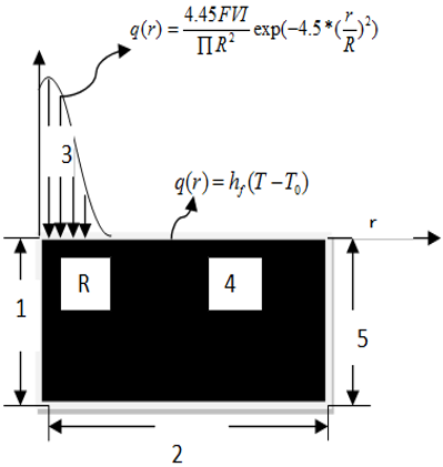
The temperature distribution along the depth of the crater still depends on time interval and is somewhat similar to the Gaussian function [13]. This is the reason the geometry shape of the crater crated after simulation (by taking Gaussian heat source) resemble to the experimental crater after machining. Hence in this analysis Gaussian heat flux has been applied to the spark radius section. Fig.2 shows the 2D domain for single spark EDM of ceramic. In the following section all the technique has been covered and are used for modelling.
3.1 Modeling Assumption
The numerical model of machining SiC/CNT Ceramic Composite can be designed by considering the discharge phenomena, which involves heating of the work piece by the incident high energy plasma. That incident area is known as Spark Radius. As the analysis is considered as transient analysis so the heat flux increases with respect to time. Both the electrodes has been considered as the isotropic in nature and subjected to Gaussian heat flux. In the following section some specific assumption has been considered to simplify the electro-thermal analysis.
Modeling involves the use of some simplifying assumptions
• Homogeneity of both tool and workpiece electrode.
• Average physical thermal characteristics (Table 1) are applied across the temperature spectrum.
• Only by the conduction is heat transferred to the surface of the electrode.
• There is insignificant radiation and convective heat loss.
• A percentage of anode- and cathode-based discharge energy is stable.
• As a heat source, the Gaussian heat flow is used.
The remainder are lost in the dielectric convection and radiation. • A fraction of the overall spark energy is disbursed as heat in the part.
• The quality of flushing shall be considered 100%. The recast coating on the machined surfaces is not deposited.
• Flushing efficiency is considered to be 100 %. There is no deposition of the recast layer on the machined surfaces.
• Temperature analysis is considered to be of transient type.
• The workpiece is free from any type of stress before EDM.
• Only one spark is considered in the analysis.
• The capacitor is fully charged and discharged during the process.
3.2 Governing Equation
In EDM process two types of heat transfer mechanism occurred which are Conduction & Convection. As the EDM mechanism starts from Penetrating the Plasma channel in to the work piece Surface, So Conduction has been considered as the main mode of heat transfer in EDM. Therefore the Fourier heat conduction equation (Eqn.1) has been solved for the analysis of the thermal modeling with no internal heat generation.
$\frac{1}{\alpha }\frac{\partial T}{\partial t}=\left[ \frac{{{\partial }^{2}}T}{\partial {{r}^{2}}}+\left( \frac{1}{r}\frac{\partial T}{\partial r} \right)+\frac{{{\partial }^{2}}T}{\partial {{z}^{2}}} \right]$ (1)
where, T is temperature, t is time, and r and z are coordinate axes. ά is the thermal diffusivity which can be represented by eqn. (2)
$\alpha =\frac{{{K}_{t}}}{\rho {{C}_{p}}}$ (2)
3.3 Heat Input to the Work Piece
In EDM process the electrical energy gets converted to the thermal energy in form of Plasma which melts the material from the work piece surface. The total energy of the plasma is the function of three variables which are Spark radius, Amount of heat flux and lastly the energy within the gap between electrodes. The detail of the three parameters of modeling has been discussed below.
3.3.1 Shape and size of plasma channel
The critical aspect for a proper numerical simulation of the EDM mechanism is determining the sparking region where the heat source must be applied. Since the mathematical model represents a single pulse, the funnelling radius can hardly be experimentally determined. There is also an aspect that is very much lower, i.e. in micro second (μS), depend on the time of pulse or pulse. The interaction of the spark radius w.r.t with the current and pulse time suggested by Ikai and Hashigushi has been used in this present analysis [9].
$R(\mu m)=2.04\times {{I}^{0.43}}\times To{{n}^{0.44}}$ (3)
where, R is in µm, I in Amp & Ton in µS.
3.3.2 Selection of heat source
For the analysis of the thermal Models of EDM, the heat source is most essential factor. Many studies have already been conducted on computational modelling of EDM using three types of heat sources, namely disc, point, and Gaussian heat sources [3-11]. Gaussian heat flux has been shown to coincide with the real case of EDM among the three forms of heat sources [4, 5, and 6]. As the heat flux that varies with time in this work, a Gaussian heat source has been used. The heat flux (q(r)) for a Gaussian heat source is given by Eqn. (4).
$q(r)=\frac{4.45{{F}_{c}}VI}{\prod {{R}^{2}}}\exp (-4.5*{{(\frac{r}{R})}^{2}})$ (4)
where Fc is the fraction of heat transferred to work piece, V and I are the discharge voltage and the supplied current respectively.
3.3.3 Estimation of fraction of heat
Due to the ultra short pulse length in a single discharge, the energy transmitted in the form of radiation and convection may be skipped. The bulk of the energy is thus transported by heat conduction to the cathode, anode, and dielectric, therefore a precise calculation of the energy ratio transmitted to the cathode is essential for reducing thermal model errors. Singh [31] showed that a portion of energy transmitted to a workpiece (Fc), which varies with current and pulse durations, is the result of pulse length, current, polarity of electrodes and a mixture of workpiece and tool electrodes.
Many analytical models [1, 2, 3, 4, 5] set the proportion of heat distribution as a fixed value, resulting in lower precision in predicting the MRR and surface roughness. The regression model of fc versus pulse current (I) and pulse length (Ton) represented in Eqn.(5), according to Ming's analysis [26], resembles the actual case of energy sharing to the work piece surface.
fc(%)=5.672+0.2713×I0.5598Ton0.4602 (5)
3.3.4 Boundary and initial condition
The following boundary conditions constrain the system (Fig.2) by equation 6:
Figure 2. Schematic 2D work domain with boundary Condition
$\begin{align} & \frac{\partial T(X,z,t)}{\partial r}=0 \\ & -K\frac{\partial T}{\partial z}(r,0,t)=\{{{E}_{0}}\text{ for 0rR, 0 for RrX }\!\!\}\!\!\text{ } \\ & \text{T(r,}\infty \text{,t)}\to {{\text{T}}_{0}} \\\end{align}$ (6)
where, E0 is the Energy density
T0 is the room temperature
X is the total width of the work domain
The Initial condition of the system is represented by $T(r,z,0)={{T}_{0}}$.
Section 1, 2 & 5 are fully insulated and the heat flux has been applied within $0\le r\le R$.
Eqn. (7) can be For the Gaussian heat source which has a finite duration of time period t, the temperature profile can be obtained using the Laplace transformation as follows by eqn. (7):
$T(r,z,t)=\frac{{{E}_{0}}{{R}^{2}}{{k}^{1/2}}}{K{{\prod }^{1/2}}}\int\limits_{0}^{t}{\frac{d{{t}^{I}}}{{{t}^{{{I}^{1/2}}}}(4K{{t}^{I}}+{{R}^{2}})}X\exp [\frac{-{{z}^{2}}}{4K{{t}^{I}}}}-\frac{{{r}^{2}}}{4K{{t}^{I}}+{{R}^{2}}}]$ (7)
Eqn. (7) has been manipulated in this study for considering the Latent heat of fusion and specific heat to make it valid for the phase change of work piece by plasma channel. This can be done by the following Eqn.-8.
${{K}^{I}}=\frac{K}{\rho }\frac{1}{{{C}^{I}}}\text{ where }{{\text{C}}^{I}}=C+\frac{m}{{{T}_{m}}}$ (8)
where, KI and CI are the adaptive thermal diffusivity and adaptive specific heat.
3.4 Latent Heat for Phase Change
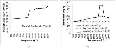
The material removal mechanism in EDM mainly involves two types of mechanism firstly melting and secondly Vaporization phenomena. However the effect of Vaporization is negligible due to the significant dynamic pressure of the plasma channel. This pressure also restricts the effect of evaporation [31, 32]. The Vaporization effect is directly proportional to the Latent heat of fusion. Earlier many researcher neglect the Latent heat effect [6-10]. In this study to enhance the accuracy of the electro-thermal modeling. The latent heat of fusion has been considered in this study by considering all the thermal properties vary according to temperature. Table-1 represents the variation of Specific heat and conductivity with respect to temperature increase. The specific heat CP has been denoted as CPeff and the mathematical formula to estimate the CPeff has been denoted below by equation-8:
${{C}_{peff}}={{C}_{p}}+\frac{{{L}_{H}}}{\Delta T}$ (9)
where LH is the workpiece latent heat of melting and ∆T=Tm-T0 the temperature difference between melting point temperature and dielectric temperature.
Table 3. Temperature Dependent [Properties of SiC -6% CNT Ceramic matrix Composite
|
*(for addition of 6 vol% CNT in SiC ceramic: LH=990 kJ/kg to be released or absorbed over the temperature range of solidus temperature Ts=1977 ˚C to liquidus temperature Tm=2250˚C [32-35] ). |
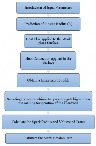
EDM is a complex process which involves many other mechanisms which makes it difficult to model it by FEM (Finite Element Method). However FEA makes it possible to predict the material removal rate from the temperature distribution profile at the end of single discharge simulation. For this study COMSOL multi physics Software has been used for the thermal analysis. Following Flow chart has been followed for estimating the Erosion rate by numerically.
The Simulation of EDM process involves solving of the Governing equation (Eqn.1). In FEA analysis the Newton–Raphson iterative process has been used to solve Eqn.(1) at discrete time points (using automatic time step function) within the transient system[22, 23]. Eqn. (10) is the differential form of the Governing equation ( Eqn.1) which has been used in FEA analysis.
$[{{C}_{g}}]\{{{T}_{g}}\}+[{{K}_{g}}]\{{{T}_{g}}\}=\{{{Q}_{g}}\}$ (10)
where [Cg] is the global capacitance or specific heat matrix, [Kg] the global conductivity matrix, [Qg] the global heat flux vector, [Tg] the global temperature. The ambient temperature is specified as the initial (starting) temperature, and subsequent temperatures are calculated by iteration. The iterative process continues until a converged solution has been achieved. The solution data such as nodal temperature, maximum temperature, and minimum temperature and all other thermal properties can be seen in a graphical form which can be used for further analysis. With appropriate boundary conditions, the temperature distribution within the workpiece is obtained (Along the Depth and Radius). From that temperature Profile the nodes which are above the melting point has been eliminated and the actual crater obtained. The Volume of the obtained geometrical shape and Erosion rate can be calculated from the following equation.
4.1 Fem Parameters and Meshing Details
The Work piece dimension which has to be considered for the experimental purpose has been modeled as 2D Continuum of Dimension 300µmX300µm. For the Spark Channel a selected region has been considered over the work piece surface according to Eqn. (3). The meshing of the Spark Channel area has been denser w.r.t the other area of the work piece for proper simulation. Fig.3 shows the meshed domain of work piece. To Simulate the Process Transient Heat transfer physics has been applied. In this Section the three Boundary Conditions which has been discussed in above section has been applied to the domain. The Gaussian heat flux has been applied on the Conduction boundary Zone. Rest of the area on the work piece surface is being exposed to Convection boundary Condition. As the bottom surface of the work piece is far away from the Conduction Zone, so it can be considered as thermally insulated. All the other selected properties have been tabulated on Table. 3 & 4.
Algorithm of EDM simulation
Table 4. Details of input parameters for transient time dependent study
|
Analysis type: |
Two-dimensional thermal transient |
|
Element used: Nodes per element: |
Four-node 75(axi-symmetric) 20 |
|
Time step: |
Automatic |
|
Iterative method: |
Newton–Raphson |
Table 5. Details of Physical parameters used for simulationsimusimulation
|
Meshing type: |
Mapped |
|
Spark radius: |
1.8 μm |
|
Convective heat transfer coefficient: |
500(W/m2 K) |
|
Work material: |
|
|
Initial temperature: |
20°C |
|
FEM domain size: |
300 *300 µm |
|
Spark on time: |
25, 50, 75 µs |
|
Discharge voltage: |
50 V |
|
Capacitance: |
0.1 μF |
|
Electrode material: |
Cu-W |
Figure 3. Mapped meshing of the work piece Domain
4.2 Validation of Fem Model with Analytical Models
To strengthen the FEM model of EDM of SiC/CNT Ceramic matrix Composite, our model has been compared with the analytical models which has been described in Section-1. In the first Gaussian model i.e DiBotonto model the error percentage has been coming above 90%. Similarly in Joshi model the error percentage reduced to below 90% due to the effect of Functional Spark Radius and 5% Fractional heat. In Ming Model the percentage of Error reduced further due to 9% Fc .Table-7 represent the validation of our FEM Model with the analytical models with different Fraction of heat percentage. As the minimum error has been obtained from Ming Model, So for further analysis of MRR & Specific Discharge Energy Fc has been considered as 9%.
Table 6. Comparison between various theoretical models and FEM Model
|
Sl. No |
I (A) |
V (V) |
Ton(µS) |
FEM Model |
Theoretical Model by Dibotonto |
Error (%) |
Theoretical Model by S. Joshi |
Error (%) |
Theoretical by Ming |
Error (%) |
|
1 |
1 |
30 |
25 |
0.71435 |
9.05386565 |
92.11 |
4.20205882 |
83 |
1.29881818 |
45 |
|
2 |
1 |
30 |
50 |
0.9508 |
14.1910448 |
93.3 |
8.06446141 |
88.21 |
1.94915949 |
51.22 |
|
3 |
1 |
30 |
75 |
0.9917244 |
12.8795377 |
92.3 |
6.1982775 |
84 |
2.0401654 |
51.39 |
|
4 |
2 |
30 |
25 |
0.378159 |
5.82679507 |
93.51 |
2.53797987 |
85.1 |
0.78783125 |
52 |
|
5 |
2 |
30 |
50 |
0.301813 |
5.54803309 |
94.56 |
2.11058042 |
85.7 |
0.6159449 |
51 |
|
6 |
2 |
30 |
75 |
1.029736 |
10.9036002 |
90.556 |
7.10162759 |
85.5 |
1.95841765 |
47.42 |
|
7 |
3 |
30 |
25 |
1.299492 |
16.3252764 |
92.04 |
7.64407059 |
83 |
2.35415217 |
44.8 |
|
8 |
3 |
30 |
50 |
1.118672 |
13.9834 |
92 |
6.58042353 |
83 |
2.33056667 |
52 |
|
9 |
3 |
30 |
75 |
1.097242 |
17.4165397 |
93.7 |
7.83744286 |
86 |
2.24890756 |
51.21 |
|
10 |
4 |
30 |
25 |
1.299492 |
23.3301975 |
94.43 |
7.64407059 |
83 |
2.40646667 |
46 |
|
11 |
4 |
30 |
50 |
1.157247 |
8.97090698 |
87.1 |
9.74113636 |
88.12 |
2.15141662 |
46.21 |
|
12 |
4 |
30 |
75 |
1.70682 |
13.2311628 |
87.1 |
7.79369863 |
78.1 |
3.10330909 |
45 |
|
13 |
5 |
30 |
25 |
1.693277 |
37.2148791 |
95.45 |
7.36207391 |
77 |
3.76283778 |
55 |
|
14 |
5 |
30 |
50 |
1.157247 |
16.5321 |
93 |
5.05789773 |
77.12 |
2.46800384 |
53.11 |
|
15 |
5 |
30 |
75 |
1.70682 |
15.5165455 |
89 |
7.42095652 |
77 |
3.71047826 |
54 |
4.3 Validation
4.3.1 DETERMINATION OF MRR
In actual practice the MRR of the EDM Process depends on several factors like frequency of sparks, flushing efficiency, phase change of electrodes, random behavior of debris particles, etc. Due to the complex mechanism of EDM it is critical to estimate the exact numerical simulation. But by calculating the total crater volume Cv, from the temperature contour plot, the MRR (mm3/min) has been estimated by the following equation.
$MRR=\frac{{{C}_{v}}*NOP}{{{T}_{mach}}}$ (11)
where, Cv=Crater Volume (mm3)
NOP=Number of Pulse
Tmach=Machining time in minute
In Table-5 a comparative study of the numerical MRR and Experimental MRR has been presented. From the results it has been cleared that at high current i.e 3A least error (about 4%) has been recorded. Similarly the highest MRR i.e 1.09 mm3/min has been obtained for the 3A, 50V and 75µS parameters. The least MRR has been obtained for 1A current, 25µS.
Table 7. Comparison of MRR between FEM Model and Experimental Results
|
Sl.No. |
I (A) |
Ton(µS) |
Power (mJ) |
MRR (mm3/min) (FEM ) |
Experimental MRR (mm3/min) |
Error (%) |
|
1 |
1 |
25 |
0.75 |
0.71435 |
0.21 |
70.602645 |
|
2 |
2 |
1.5 |
0.9008 |
0.3 |
20.668290 |
|
|
3 |
3 |
2.25 |
0.9517244 |
0.41 |
68.449209 |
|
|
4 |
1 |
50 |
1.5 |
0.98159 |
0.45 |
52.671434 |
|
5 |
2 |
3 |
0.901813 |
0.5 |
50.300351 |
|
|
6 |
3 |
4.5 |
1.029736 |
0.71 |
36.531887 |
|
|
7 |
1 |
75 |
2.25 |
1.299492 |
0.78 |
58.571546 |
|
8 |
2 |
4.5 |
1.118672 |
0.9 |
12.598957 |
|
|
9 |
3 |
6.75 |
1.097242 |
1.05 |
4.3055223 |
4.3.2 Determination of SDE
Theoretically MRR is defined as the volume of removed material in a unit of time. Thus, the product of the MRR and the duration of the EDM process are the volume of the eroded material, which is defined by the Equation -12 as follows:
$SDE=\frac{V*I*Ton}{(MRR*(Ton+Toff))}$ (12)
Table 8. Comparison of SDE between FEM Model and Experimental Results
|
Sl.No. |
I (A) |
Ton(µS) |
Discharge Power (mJ) |
Numerical SDE (J/mm3) |
Experiment SDE (J/mm3) |
Error (%) |
|
1 |
1 |
25 |
0.75 |
142.33 |
152.04082 |
-6.82275 |
|
2 |
2 |
|
1.5 |
113.331014 |
92.857143 |
18.06555 |
|
3 |
3 |
|
2.25 |
109.469881 |
86.794425 |
20.71388 |
|
4 |
1 |
50 |
1.5 |
86.2936475 |
55.555556 |
35.62034 |
|
5 |
2 |
|
3 |
65.665495 |
73.333333 |
-11.6771 |
|
6 |
3 |
|
4.5 |
67.0437805 |
65.633803 |
2.10307 |
|
7 |
1 |
75 |
2.25 |
63.4415072 |
59.659443 |
5.961498 |
|
8 |
2 |
|
4.5 |
41.6195441 |
37.619048 |
9.612062 |
|
9 |
3 |
|
6.75 |
58.5884557 |
51.22449 |
12.56897 |
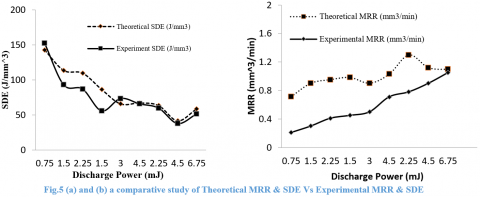
In Table-6 the Experimental result of EDM has been validated with the FEM model. Based on Equation no.12 respective Specific Discharge Energy (SDE) has been calculated. It can be seen that the least error between the experimental and theoretical model has been estimated at high Pulse-On time and high Peak Current. The least error between theoretical SDE and Experimental SDE recorded as 2.10% at 3A current and 50µS pulse-On time. Similarly the highest SDE recorded as 142.33 Jmm3 at 1A, 25µS Ton. SDE should be constant as a property describing material performance in EDM [5], irrespective of manufacturing conditions. But as the numerical model has been established considering some assumption, the difference between actual machining and simulated machining cannot be completely disregarded, thus SDE fluctuation is inevitable [6].
Fig. 5 (a) indicates the comparison between Discharge power vs SDE. For a single discharge EDM Discharge energy/ power depends on the current & voltage. From Liao study on wire EDM the Discharge energy ‘E’ can be obtained from the following equation
$E=V*I*{{T}_{on}}$ (13)
From the trend line of fig.5 (a) of it can be concluded that with the increase in discharge power the SDE value decreases due to the high erosion rate. The highest erosion rate can be recorded at 0.75 Discharge energy. Similarly at high discharge energy the difference between the theoretical and the experimental values of SDE decreases (3 mJ onwards). In fig. 5 (b) a comparative study of MRR with Discharge power has been presented. At high Discharge power highest MRR of 1.09 mm3/min has been estimated. The least error between experimental and theoretical has been found out at highest MRR.
The FEM model of SiC/CNT Ceramic composite has been validated with the experimental result in the above section. To know the effect of parameters (Peak Current, Voltage & Pulse-On time) on the process parameters (MRR & Crater geometry) it is necessary to carry out the parametric study. The numerical model (FEM Model) has been used for the parametric study. To determine the metal erosion rate it has been necessary to obtained temperature profile by simulating the work model using proper boundary condition. The significance of this parametric study is to understand the quality of how a parameter affects the MRR of SiC/CNT Ceramic Composite while working under different machining conditions of EDM.
The following set of parametric study has been done for the analysis:
Temperature Profile & Crater formation
Influence of Specific heat on MRR
Effect of Pulse-On time on MRR
Effect of Current on Crater Geometry
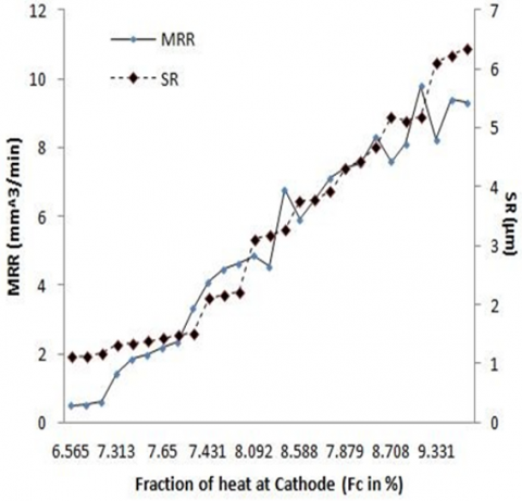
5.1 The Effect of Heat Fraction on MRR and SR
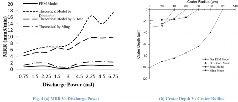
In this study a comparative review was conducted for the mathematical calculation of MRR and SR. In Figure 4, a comparison of MRR and SR has been made. The research indicates that for high the erosion rate needed for macro machining Fc should be between 7.23% and 9.11%. Likewise, for micro machining, an Fc of less than 6.2% is recommended. However, at a higher MRR and SR also rise as well. This can be accomplished by surface eradication phase of completion. Similarly, when the MRR is big, the surface finish is poor.
Figure 6. Variation in MRR and SR w.r.t Fc
As a result of Figure 6, it can be inferred that at 6.3 to 6.7% of 'F' the error between the two versions is between 41 and 48%. Similarly, the error falls from 45% to 35% in 7.13 to 7.2'F'. 9.2 percent of 'F' has been counted with the least mistake of 27 percent. As such, itIt can be inferred that when machining SiC-6% vol CNT for EDM, the recommended fraction of heat entering the cathode should be between 9.2 and 10.11%. However, the maximum MRR of 9.74mm3/min was obtained using a statistical model at 3A, 75µS and 30 V, and 9% Dc.
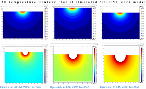
5.2 Temperature Profile & Crater Formation
Fig.6 shows the result of the temperature contour plots after Simulation of SiC/CNT wok domain. From the transient thermal analysis performed, the temperature variation over a period of time can be obtained. The nodes showing the temperature more than the melting point (For SiC/CNT the melting point is around 2242K) were selected and eliminated from the complete mesh of the work domain for MRR calculation. In fig. 6 (d) to (i) the selected nodes of maximum temperature has been eliminated to calculate the volume of crater. From the figures, it can be seen that the change in temperature with time for any point on the radial axis has a similar trend to the case of the vertical axis. For any instance of time, the temperature is highest at the origin and decreases gradually with an increase in distance from the center. This is because the Gaussian heat source, which is closer to real-life situation, is showing steep temperature gradients within the spark radius zone. The highest temperature at 3A and 75µS is 8700K, for which the MRR is 1.01mm3/min. Similarly the lowest MRR for the rise in 2400K temperature is 0.21mm3/min.
5.3 Influence of Specific Heat on the Erosion Rate
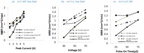
The FE simulation of SiC/CNT has been done to get the temperature contour. From that contour the numerical MRR has been calculated according to eqn. 11. Fig.7 shows a comparative study of the three different thermal properties of numerical MRR and the experimental result. In the first condition the Specific heat varies directly as the Latent heat according to equation-9. In second the Cp remains constant and in third condition Cp changes along with thermal conductivity and Latent heat. Fig.7 (a), (b) & (c) represent the MRR variation with respect to different input parameters (peak current, Voltage, Pulse-On time). Fig.7 (a) clearly indicates at high current (by keeping other parameter as constant) the numerical value of MRR (Cp varying w.r.t LH & TH) coincides with the experimental results of MRR. The highest MRR at 5A current is 1.8 mm3/min. Similarly in fig.5 (b) there is slight deviation in between the third model (Cp varying w.r.t LH & TH) and experimental results but at high Voltage (by keeping other parameter as constant) the two MRR approaches each other. In fig.7 (c) with varying Ton the deviation between the third model and experimental value is more in comparison to the fig. 7 (a) and (b), but again in high Ton 75µS the numerical MRR and experimental MRR coincide (1.01mm3/min) with each other.
The reason behind the deviation at the low input parameter condition is that, during discharge not all the molten metal can be evacuated at the end of the pulse, which subsequently gets re-solidified. Therefore, the real crater is to some extent shallower than the ideally obtained one.
Figure 7. (a), (b), (c) Comparison between Simulated Results of numerical MRR with Experimental result by varying Peak current , Voltage and Pulse-On time respectively
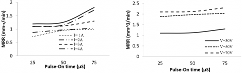
5.4 Effect of Pulse-on Timeon Erosion Rate
From the FEM model of machining of EDM it has been clear that Pulse-On time is the most significant parameter for machining by EDM. In fig. 8 (a) & (b) the effect of Pulse-On time on material erosion rate with varying current and Voltage has been shown. At low Current (1and 2A) MRR increases with increase in Ton due to the more Spark On time. But at 3A above 50µS MRR suddenly decreases due to the low Flushing pressure. At 4A and 5A the rate of increment of MRR also decreases in comparison to the Fig.8 (a) & (b). This reason leads to deposition of white layer due to reduce in Plasma flushing efficiency. The highest MRR recorded at 5A, 30V and 75 µS is 1.70 mm3/min. Similarly the lowest has been calculated for 1A, 30V and 25 µS. In fig. 8 (b) it can be concluded that at high voltage the deviation between the erosion rate between 50V and 70 V is approaches towards each other this is due to the more occurrence of more rate of spark at high voltage.
Fig.8 (a) MRR Vs. Pulse-On time at different Current (b) MRR Vs. PulseOn time at different Voltage
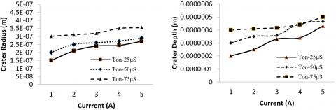
5.5 Effect of Discharge Current on Crater Dimension
The effect of discharge current on crater radius and depth is seen in Fig.9 (a) and (b) while the other parameters are kept constant (i.e V-30V). The effects on crater size of the most important parameters modulating the MRR, namely discharge current and discharge length (spark on-time) (radius and depth). Since this characteristic is directly proportional to the size of the crater depth, the results would be crucial in predicting the efficiency (MRR) of the EDM operation. It also aids in the comprehension of how a parameter impacts the MRR when operating under various machining conditions.
As the discharge current is increased from 1 to 5A, the Crater Radius graph still indicates an increase due to the higher amounts of discharge energies emitted during sparking. However, it's worth noting that the developed crater depth to radius (d/r) ratio jumps from 0.83 to 0.89. It means that the crater diameter expands faster than the crater radius, meaning that the melting boundary moves further into the workpiece as a result of strong discharge current to prevent molten material from solidifying again. In other words, as the discharge current is increased, the water ejection quality improves, with more material being removed rather than scattered over the work surface.
Fig.9 (a) Crater RadiusVs. Current at different Spark On time (b) Crater Depth Vs. Current at different Spark On time
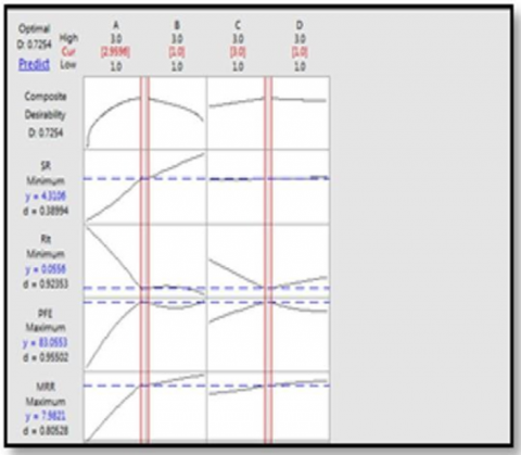
5.6 Optimization by Desirability Analysis (D)
In this study the input parameters I, Ton, Dc, and V has been used to express the results of the output responses. Desirability analyses are carried out in order to refine the input parameters. A number between 0 and 1 is allocated to each answer. The consequence is considered completely needless if the value is 0, and the most desirable or optimal condition if the value is 1. By combining all mean responses, the overall desirability (D) can be calculated and expressed as follows.
D= [d1(y1 )*(d2(y2 ))*.........*(dk(yk ))] (14)
The aim in this study is to optimise MRR, PFE, and decrease SR and Rlt. Any difference in the input parameters influences the output response, as seen in Figure 10 of the desirability analysis. As a result, choosing the right input parameters is crucial for getting the best output response. To achieve high MRR & PFE and low Rlt, SR, multi-objective optimization was used to calculate the optimal values of I, V and Ton. The optimal values of input parameters can be found by looking at the Figure's desirability analysis, which also shows the average desirability value of 0.0774.
Figure 10. Desirability test of SiC-CNT composite machining
Figure 11. SEM image of SiC-6%CNT machined at optimum condition
A validation test has been also performed using the optimal set of input parameters for SiC-6 percent CNT composite machined by EDM, namely I= 3A, V=30V, and Ton= 75µs. It is evident from Figure 11(a) that the crater formed by EDM machining resembles a hemispheric cavity. The thickness of the White film can also be seen on the crater's outer periphery rim. The existence of MWCNT structure within the composite can be seen in the longitudinal grain.
In this study a nonlinear, transient axi-symmetric model has been designed to solve the numerical modeling of the SiC/CNT Ceramic composite machining by Die Sinking EDM. The numerical analysis has been performed by considering Specific Discharge Energy & Varying Latent heat. The numerical model has been verified with the Theoretical/Analytical models along with the experimental validation. From the present analysis the following conclusion can be withdrawn.
The introduction of Specific Discharge Energy in the modeling increases the model accuracy.
The material erosion rate increases when the Specific discharge energy decreases.
The Thermal Conductivity and Specific heat values suddenly increase from 1100K to 2500K.
By introducing the varying thermal properties (Thermal Conductivity, Latent heat) the Material removal rate of numerical modeling becomes closer to the experiment results.
In between the three different values of Fraction of heat to cathode (Fc) 3% and 5% are the most acceptable range for numerical modeling.
At low current the error between the material removal rate of numerical modeling and experimental results is more than at high current.
At high Voltage the shape of the Crater geometry gives more realistic value in comparison with the experimental crater.
By varying the pulse-On time at different Current (1A to 5A) and Voltage (30V to 70V) the increase in Metal removal rate is more during high value of input parameters.
For the numerical analysis Ceramic Composite the peak current and Pulse-On time are the two significant factors for metal erosion rate.
The highest removal rate has been obtained in numerical model at 3A, 75µS and 30 V is 1.09mm3/min whereas in same parametric condition the experimental results is 1.05mm3/min.
At high value of input parameters the error between the metal removal rate and Specific discharge Energy reduces.
The Desirability analysis shows that the optimal setting for machining SiC-6%vol CNT by Die sinking Electrical discharge machining is I = 3A, V = 30 V, and Ton = 75 µS is i.e., 7.255 mm3/min for MRR, 87% for Plasma flushing efficiency
This thermal modelling has been proved to be a robust model which can be used to predict the removal rate of SiC/CNT composite used for battery and electrode machined by EDM.
[1] K.A. Terrani, J. Kiggans, C.M. Silva, C. Shih, Y. Katoh, L.L. Snead, Progress on matrix SiC processing and properties for fully ceramic micro encapsulated fuel form. J. Nucl. Mater. 457, 9–17 (2015)
[2] Q. Li, X. Yin, L. Zhang, L. Cheng, Effects of SiC fibers on microwave absorption and electromagnetic interference shielding properties of SiC f/SiCN composites. Ceram. Int. 42(16), 19237–19244 (2016)
[3] H. Mei, H. Wang, N. Zhang, H. Ding, Y. Wang, Q. Bai, Carbon nanotubes introduced in different phases of C/PyC/SiC composites: effect on microstructure and properties of the materials. Compos. Sci. Technol. 115, 28–33 (2015)
[4] B. Bhattacharya, BN Doloi, SK Sorkhel. Experimental investigations into electrochemical discharge machining (ECDM) of non-conductive ceramic materials. J Mater Process Technol;95:145–54(1999).
[5] MM Schwartz. Engineering applications of ceramic materials: Source book. Ohio: American Society for Metals Metals Park; (1985).
[6] YH Liu, XP Li, RJ Ji, LL Yu, HF Zhang, QY Li. Effect of technological parameter on the process performance for electric discharge milling of insulating Al2O3 ceramic. J Mater Process Technol;208:245–50(2008).
[7] Anon. USA advanced ceramics demand. Mater Technol;20:168 (2005).
[8] SW Yao, H,Wang SL Wang. The study and application of the special ceramics. Ind Heat;35:1–4 (2006).
[9] JH Zhang, TC Lee, WS Lau. Study on the electro-discharge machining of a hot pressed aluminum oxide based ceramic. J Mater Process Technol ; 63:908–12(1997).
[10] Y Liu, Z Jia, J Liu. Study on hole machining of non-conducting ceramics by gas filled electrodischarge and electrochemical compound machining. J Mater Process Technol;69:198–202 (1997).
[11] CJ Luis, I Puertes, G Villa. Material removal rate and electrode wear study on the EDM of silicon carbide. J Mater Process Technol;164:889–96 (2005).
[12] BK Jang, Y Sakka. Thermophysical properties of porous SiC ceramics fabricated by pressureless sintering. Sci Technol Adv Mater;8:655–9 (2007).
[13] MH Chen, L Gao, JH Zhou, M Wang. Application of reaction sintering to the manufacturing of a spacecraft combustion chamber of SiC ceramics. J Mater Process Technol 129:408–11(2002).
[14] K. Aly, M. Lubna, P.D. Bradford, Low density, three-dimensionally interconnected carbon nanotube/silicon carbide nanocomposites for thermal protection applications, Journal of the European Ceramic Society, Volume 41, Issue 1, (2021)
[15] Zhang, Y.; Hu, K.; Zhou, Y.; Xia, Y.; Yu, N.; Wu, G.; Zhu, Y.; Wu, Y.; Huang, H. A Facile, One-Step Synthesis of Silicon/Silicon Carbide/Carbon Nanotube Nanocomposite as a Cycling-Stable Anode for Lithium Ion Batteries. Nanomaterials, 9, 1624. (2019)
[16] P. Chaudhury, S. Samantaray,. Finite element modelling of EDM of aluminum particulate metal matrix composites considering temperature dependent properties. Revue des Composites et des Materiaux Avances, Vol. 29, No. 1, pp. 53-62. https://doi.org/10.18280/rcma.290109 (2019)
[17] P. Chaudhury, S. Samantaray, Electro thermal modelling of electrical discharge machining of Be-Cu alloy by varying fraction of energy. Annales de Chimie-Science des Matériaux, Vol. 43, No. 4, pp. 273–279 (2019)
[18] P. Chaudhury, S. Samantaray Manufacturing Multi-optimization of process parameters for machining of a non-conductive SiC ceramic composite by non-conventional machining method Rev., 7 32 DOI: https://doi.org/10.1051/mfreview/2020027, (2020)
[19] VN Burlayenko, H Altenbach, T Sadowski modelling functionally graded materials in heat transfer and thermal stress analysis by means of graded finite elements. Appl Math Model 45:422–438(2017)
[20] P. Chaudhury, S. Samantaray, S. Sahu,. Multi response optimization of powder additive mixed electrical discharge machining by Taguchi analysis. Mater Today Proceeding, 4: 2231-2241(2017).
[21] P.Chaudhury, S.Samantaray, S.Sahu, Optimization of process parameters of powder additive-mixed electrical discharge machining. In: Innovative Design and Development Practices in Aerospace and Automotive Engineering, ed: Springer, pp. 415-425. (2017).
[22] P. Chaudhury, S. Samantaray, Role of carbon Nano Tubes in surface modification on electrical discharge machining -a review. Mater Today: Proceeding, 4(2, Part A): 4079-4088. (2017).
[23] DD DiBitonto, MR Patel, MA Barrufet, PT Eubank. Theoretical models of the electrical discharge machining process. I. A simple cathode erosion model. Journal of Applied PhyGraphite Flakes 66(9): 4095–4103. https://doi.org/10.1063/1.343994 (1989).
[24] FS ,Dijck WL Dutre. Heat conduction model for the calculation of the volume of molten metal in electric discharges. Journal of Physics D Applied Physics 7(6): 899. https://doi.org/10.1088/0022-3727/7/6/316 (1974).
[25] R Snoeys, F.Dijck Investigation of electro discharge machining operations by means of thermo-mathematical model. CIRP Annal 20(1): 35-37. (1971).
[26] JV. Beck Transient temperatures in a semi-infinite cylinder heated by a disk heat source. International Journal of Heat & Mass Transfer 24(10): 1631-1640. https://doi.org/10.1016/0017-9310(81)90071-5(1981).
[27] ST Jilani, P. Pandey (1982). Analysis and modeling of EDM parameters. Precisions Engineering 4(4): 215–221. https://doi.org/10.1016/0141-6359(82)90011-3
[28] S Joshi, S. Pande Thermo-phyGraphite Flakesal modeling of die-sinking EDM process. Journal of Manufacturing Process 12(1): 45–56. https://doi.org/10.1016/j.jmapro.2010.02.001(2010).
[29] K.Salonitis Thermal modeling of the material removal rate and surface roughness for die-sinking EDM. International Journal of Advance Manufacturing Technology 40(3-4): 316–323. https://doi.org/10.1007/s00170-007-1327-y(2009).
[30] HK Kansal, S Singh, P.Kumar Numerical simulation of powder mixed electric discharge machining (EDM) using finite element method. Mathematical and Computer Modelling 47: 1217–1237. https://doi.org/10.1016/j.mcm.2007.05.016(2008).
[31] A Al-Khazraji, AS Ali, S. Mahmood The effect of graphite flakes powder mixing electrical discharge machining on white layer thickness, heat flux and fatigue life of AISI D2 die steel. Engineering Science and Technology, an International Journal 19(3): 1400-1415. https://doi.org/10.1016/j.jestch.2016.01.014(2016).
[32] R Karthikeyan, D Kanagarajan, K Palanikumar, P Sivaraj. Influence of process parameters on electric discharge machining of WC/30%Co composites. Proceedings of the Institution of Mechanical Engineers, Part B: Journal of Engineering Manufacture.;222(7):807-815. doi:10.1243/09544054JEM925 (2008)
[33] K Ponappa , S Aravindan , P.V. Rao , J.Ramkumar , M.Gupta , The effect of process parameters on machining of magnesium nano alumina composites through EDM . International Journal of Advanced Manufacturing Technology, 46, 1035 – 1042 (2010).
[34] UK Vishwakarma, A Dvivedi, P.Kumar Finite element modeling of material rem oval rate in powder mixed electric discharge machining of al-sic metal matrix composites. Materials Processing Fundamentals 151-158. https://doi.org/10.1007/978-3-319-48197-5_17(2013).
[35] KT Hoang, SK Gopalan, SH.Yang. Study of energy distribution to electrodes in a micro-EDM process by utilizing the electro-thermal model of single discharges. Journal of Mechanical Science and Technology 29(1): 349–356. https://doi.org/10.1007/s12206-014-1241-9 (2015)
[36] D Puhan, SS Mahapatra, J Sahu, L Das. A hybrid approach for multi-response optimization of non-conventional machining on AlSiCp. MMC, Measurement 46(9): 3581-3592. https://doi.org/10.1016/j.measurement.2013.06.007 (2013)
[37] DK Singh, SC.Jayswal Thermo physical modeling of powder mixed EDM using ANSYS10.0. International Journal for Scientific Research & Development 3(12): 2321-0613. (2016).
[38] G Talla, DK Sahoo, S Gangopadhyay, CK Biswas. Modeling and multi-objective optimization of powder mixed electric discharge machining process of aluminum/alumina metal matrix composite. Engineering Science and Technology an International Journal 18(3): 369-373. 369e373. https://doi.org/10.1016/j.jestch.2015.01.007(2015).
[39] V Vipin, B Kuriachen, R Manu, J.Mathew Experimental and finite element based investigations on powder mixed micro-electrical discharge machining of Ti-6Al-4V alloy. 5th International & 26th All India Manufacturing Technology, Design and Research Conference (AIMTDR 2014) IIT Guwahati, Assam, India334-1 (2014).
[40] L. Tang, Y. Ji1 , L. Ren, K. G. Zhai1 , T. Q. Huang, Q. M. Fan, J. J. Zhang, J. Liu, Thermo-electrical coupling simulation of powder mixed EDM SiC/Al functionally graded materials The International Journal of Advanced Manufacturing Technology https://doi.org/10.1007/s00170-019-04445-z (2019)