Hamza Bahri | Abdelghani Harrag*
© 2021 IIETA. This article is published by IIETA and is licensed under the CC BY 4.0 license (http://creativecommons.org/licenses/by/4.0/).
OPEN ACCESS
In consequence of increasing global energy consumption, the environmental problems such as pollution and the drain of conventional energy resources such as coal, gas and liquefied petrol. To tame this by implementing seeming technology of renewable energy, hydrogen is one of the promising alternative fuels for the future because it has the capability of storing energy of high quality. Therefore, the hydrogen has been visualized to become the cornerstone of future energy systems. It is produced from water electrolysis under electrochemical interaction. Water electrolyzer converts electricity into chemical energy which produces hydrogen and oxygen; this can be achieved by passing DC electric current between two electrodes separated by electrolyte. The direct electric current is delivered by source renewable energy, photovoltaic or wind system. In this paper the different parts of indirect coupling PV with alkaline electrolyzer for hydrogen production have been studied and investigated using Matlab Simulink environment. The developed models allow us the analysis of current-voltage characteristics for both systems PV and Electrolyzer, respectively, as well as the principal parameters affecting the performance of the alkaline electrolyzer.
Photovoltaic, PV, Fuel cell, PEMFC, Electrolyzer, MPPT
In recent years, exacerbation of global warming, diminishing fossil energy, oil price fluctuating, increasing demand electrical energy have strengthened the position of renewable energy sources to overcome these drawbacks. Among the current renewable energy sources such as wind, geothermal and biomass, solar energy has been increasingly emphasized as an effective alternative for traditional energy sources because environmental-friendly, widespread, free and available to everyone [1-2]. In addition, its reserves are huge, as it sends out about 3.8 x 10²³ kW per second, which is great if exploited well. With the current technological development, the methods of using solar energy have multiplied, such as photovoltaic for power generation, solar thermal collection for water heater, supply heating and heat pump and photo-electrolysis for hydrogen production [3-6].
The technology of photovoltaic (PV) allows transforming the energy solar to electrical energy without the help of machines or any moving devices [7]. Solar energy is captured by photovoltaic panels; these panels are composed of semi-conductor materials which have the property of generating electricity when it receives sunlight [8]. Indeed, when solar energy knocks electrons from their atoms, these electrons become free and flow through these materials, producing electrical voltage. This process of converting light (photons) to electricity (voltage) is called the photovoltaic effect [9].
The electrical power produced from the PV system is used in several fields, it used for water pumping, Lighting street, in remote area, Building integrated photovoltaic systems, water desalination, weather monitoring, for space vehicles, for communications, for satellites and even for megawatt-scale power plants [10]. PV systems, however, have some drawbacks such as output power is highly dependent to the climatic conditions, nonlinear voltage-current and unavailability power during night hours as well as during cloudy periods. Therefore, it is necessary control on output power as well as availability of generation during the absence power from PV panels [11]. Energy storage is considered as solution to cope with major drawbacks of PV systems. Chemical energy (e.g. hydrogen) is one form of this energy used for storage and transportation [12]. In a future global energy system that relies mostly on renewable energy sources, hydrogen has the potential to meet energy storage needs at the required scale [13].
Hydrogen is considered to be one of the most promising energy carrier due to its high energy density, transportable, storable for a long time, recyclable, synergistic, versatility, and flexibility of conversion to other forms of energy, as well as is environmental benign [14]. Currently the most effective way to exploit hydrogen energy is by using fuel cells, because they convert chemical energy into electrical energy. In the fuel cell, hydrogen and oxygen merge together into an electrochemical reaction and the result is the production of electricity, water and heat [15].
The chemical properties of hydrogen show it to be the simplest of the elements, where the hydrogen atom consists of only a proton and an electron, making it the lightest element. In addition, it is considered the most abundant element in the universe, making up more than 90% of known matters, especially water and organic compounds [16]. Hydrogen can be obtained from a numerous sources, whether traditional or renewable such as nuclear, natural gas, oil and coal, biomass, solar, wind, hydroelectric, or geothermal energy [17-18]. It is therefore desirable for hydrogen to be generated using a variety of resources and process technologies. Currently, several technologies are available to produce hydrogen [19], natural gas reforming represent the main hydrogen production method at a rate of 48%, followed by oil (30%) and coal (18%) [18]. The disadvantage of this method is that the coproduct of the reaction is carbon dioxide, which is a greenhouse gas, causing serious environmental problems [20]. For this reason, other hydrogen production methods have been developed based renewable energy sources such as solar water splitting [21], Methane steam reforming based solar energy [22], biomass gasification based solar energy [23], thermochemical cycle [24], biological method [25], photochemical method [26], electrolysis of water [27], photovoltaic/thermal hybrid system hydrogen generation with electrolysis method [28], solar/wind thermochemical hydrogen production method [29], PV/photon-enhanced thermionic emission hydrogen production method [30], Solar thermochemical ammonia decomposition system with membrane reactor method [31].
The most effective way to exploit hydrogen energy is by using fuel cells devices. In the fuel cell, hydrogen and oxygen merge together into an electrochemical reaction to produce electricity as well as byproducts are discharged as water and heat [32]. Hence, fuel cell confirms the role of hydrogen in the energy infrastructure of the future. Among six types of fuel cells available in the market, Proton exchange Membrane Fuel Cell (PEMFC) is favorable candidate due to its higher power density, it efficiency (40-60%), has a quick start up and operates at lower operating temperature (between 60°C and 80°C) [33-34]. PEMFC is continuous source electrical energy as long as there is supplying by hydrogen at high levels of efficiency and power density, it suited to transportation applications. Yun et al. [35] have reviewed the three applications of PEMFC in the transportation, stationary, and portable sectors through an overview of the state-of-the-art and most recent technical progress. So far, the operational lifetime for real life applications does not satisfy the requirements for state-of-the-art technologies, e.g., 5000 h for cars, 20,000 h for buses, and 40,000 h for stationary applications [36]. During long-term operations, PEMFC components suffer degradation, especially the part so-called the membrane electrode assembly [37]. Cost, durability and performance degradation of PEMFC are the main critical challenges for the commercialization of this technology [38]. Air pollutants, fuel impurities, detergents and other materials that go into their manufacture are proven to be a serious concern affecting their technical economy, durability, reliability and performance [39]. Hydrogen consumed by PEMFC through anode may contain impurities such as CO, CO2, H2S, Cl−1, etc. In [40], the effect of CO on the performance of the PEMFC is discussed, as it was noted that the CO poisoning effect arises because CO is absorbed preferentially on the surface of the platinum catalyst during chemical reaction. Hence, the CO blocks sites for the dissociation of adsorbed hydrogen molecules and as a result, the hydrogen oxidation reaction is hampered.
Very pure hydrogen is indispensable for higher performance and longer operating life time of the PEMFC. Water electrolysis is the most developed process and easy, which is currently being attracted the attention of researches for high concentration pure hydrogen production [41-42]. It used only water as reactant, and is widely available as long as there is a possibility of using sea water for electrolysis [43]. Generally, the principal operation of electrolyzer is exactly the opposite of the fuel cell operation; water electrolysis will need electrical energy to converter electricity into chemical energy via decomposition of water into hydrogen and oxygen [44]. This process takes place in electrolyzer device and produces hydrogen without any waste material. There are three types of electrolyzer available in the market, namely alkaline electrolyzer, proton exchange membrane electrolyzer (PEM) and solid oxide electrolyzer (SOE) [44].
Using photovoltaic energy generators to feed water electrolysis hydrogen production systems by electrical energy are the best configuration that can be coupled together because it is the configuration in which large quantities of sustainable hydrogen can be produced without any emission of pollutant gasses and the most mature technology [45]. Despite, the photovoltaic energy technology is well known, the combination between PV/Electrolyzer has still some challenges [46]. The importance of optimal matching between photovoltaic generators and electrolyzer is one of the most important challenges facing these technologies, especially in changing climatic conditions (irradiance and temperature) [47]. PV generators and electrolyzer can be found directly or indirectly coupled. The direct coupling method, which is considered the least complex in terms of components and the least cost, but this type of connection, lacks efficiency when the PV generators and electrolyzer are not designed and selected correctly [46].Therefore, the direct coupling mode needs more researches. It has been reviewed in many literatures such as [48-53]. On directly connected systems, it suffers greatly from a mismatch between the current-voltage characteristic of PV and the Electrolyzer; hence, the operating points are far apart, which results in a high power transmission loss. To outdo this problem, using a DC/DC converter with Maximum Power Point tracking as a coupling system between PV generators and Electrolyzer. This strategy enables higher design flexibility with the possibility of having the optimum working point of the photovoltaic generator at maximum power point. Many literatures have reviewed the indirect coupling of PV/Electrolyzer systems based on MPPT controller. H. Solmecke et al [54]. Explained the benefits of introducing inverters to solar hydrogen systems, as the results gave an increase in the efficiency of the system, because the DC/DC converter that built has an efficiency between 92±95% and thus led to an increase in the value of hydrogen production. E. Bilgen [55], investigate the performance of photovoltaic-electrolyzer systems using sequential dichotomous search based MPPT with sun tracking panels or fixed; it was found that the overall thermal efficiency of the photovoltaic-electrolyzer system with the sun tracking panels was 10.85% and for the fixed panels it was 10.33%. G. E. Ahmad et al [56], presented an experimental system containing a small PV source connected to the electrolyzer with and without the use of MPPT for the purpose of hydrogen production. The experimental results showed good results in the case of using MPPT, as the system efficiency increased by 2.3% compared to 1.5% without using MPPT, which reflected positively on the flow rates of hydrogen production. T. Tafticht et al [57], presented a comparison of some conventional methods of MPPT used in photovoltaic (PV) systems such as Maximum voltage based MPPT, Maximum current based MPPT, Incremental conductance (IC) based MPPT, Power derivative based MPPT, perturbation and observation (P&O) based MPPT and propose a new approach that uses a nonlinear expression of the optimal voltage in combination with perturbation and observation (P&O) methods. The simulation results show that with this method, the MPP tracking efficiency is clearly improved and more power is extracted from PV modules. Implementation of such a method in PV systems with hydrogen production capability will increase the hydrogen production and storage rate. R. Garcıa-Valverde et al [58], proposed photovoltaic generator-proton exchange membrane (PEM) electrolyzer system with three different coupling options: (a) direct coupling; (b) through a DC/DC converter following an MPPT algorithm; and (c) through a DC/DC converter following the Safe Optimum Searching Algorithm. The result of simulation demonstrate that the use last coupling mode shows a better adaptability to the variable conditions climatic (radiation) and leads to make more flexible the sizing of the system as a whole, also provides an optimal match at the two operating points between PV/Electrolyzer. A. A. Nafeh [59], suggested stand-alone PV/PEM electrolyzer system to generate pure hydrogen, the system whole consists of the PV array, DC/DC converter with MPPT, and PEM electrolyzer. To operate the system at the the maximum power point (MPP) for every instant, neural network based MPPT together with the action of the PI controller developed. The simulation results indicate the improved relative performance of the suggested hydrogen production system in producing higher hydrogen rates at all working conditions compared with the direct coupling between the PV/PEM electrolyzer. Y. N. Anagreh et al [60], proposed new MPPT algorithm combines both IC and Fuzzy Logic Control (FLC) algorithms and enhanced with PI controller for off-grid PV system equipped with storage batteries and electrolyzer to achieve fixed DC voltage and higher efficiency, under changing radiation level. The simulation results obtained were compared with P&O and INC to validity this approach. Under rapid changes in solar irradiation, the highest output power and maximum tracking efficiency were obtained, using the proposed algorithm. In addition, it leads to a high performance output power response during dynamic and steady state conditions.
Currently, the photovoltaic systems are used in several applications such as stand-alone and grid-connected, researchers have developed technique of MPPT due to its merits in terms of the cost of energy generated and the performance, that give maximum power under varying operating conditions. To date, great number methods of MPPT algorithms have been reported in the literatures such as: P&O, IC, FLC, Sliding mode control (SC), Extremum seeking control (ESC), Artificial Neural Network (ANN), Particle Swarm Optimization (PSO) ...etc. [61-62].
The aim of this paper is to study the indirectly coupling of the PV/Alkaline electrolyzer to produce hydrogen with Variable Step Size perturbation and observation (P&O) based MPPT. The models of both systems PV and electrolyzer have been presented in the form of mathematical equations and by using Matlab-Simulink models to illustrate the different characteristic curves and analysis the several elements affecting the operating of these systems among them: i) The MPPT control used for PV system to deliver the maximum power available; ii) The optimum number of alkaline water electrolyzer cells, and iii) The operating temperature effect in different characteristics of alkaline water electrolyzer.
The main contributions of this study can be summarized as follow:
i) the energy source is the photovoltaic system is modelled and improved by the use of a variable step size stateflow P&O model;
ii) different cell configurations with different number of cells were simulated to search the optimum operating point between PV and alkaline-Electrolyzer;
iii) the performance of the alkaline-Electrolyzer affected by changing in temperature, voltage, faraday efficiency and hydrogen production rate have been evaluated showing a good concordance reliability between the developed models and the mathematical system models.
The remainder of this paper is organized as follows. Section 2 presents: the PV modelling, the MPPT controller and the water electrolysis process. Section 3 is dedicated to results and discussion. Section 5 stated the main conclusions of this work.
2.1 PV system modeling
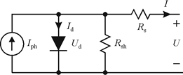
The PV cell can be presented by the equivalent circuit of Fig.1.
Fig. 1 PV equivalent circuit model [63].
The output current of PV cell Ipv is given by [64-65]:
$\mathrm{I}_{\mathrm{pv}}=\mathrm{I}_{\mathrm{ph}}-\mathrm{I}_{\mathrm{s}}\left(\mathrm{e}^{\frac{\mathrm{q}\left(\mathrm{Vpv}+\mathrm{Ipv} \mathrm{R}_{\mathrm{s}}\right)}{\mathrm{NKT}}}-1\right)-\frac{\mathrm{v}_{\mathrm{pv}}+\mathrm{I}_{\mathrm{pv}} \mathrm{R}_{\mathrm{s}}}{\mathrm{R}_{\mathrm{sh}}}$ (1)
where
Ipv is the current of the PV cell I.
Iph is the light-generated photocurrent.
Is is the reverse saturation current of the diode.
q is the electron charge.
Vpv is the voltage of the PV cell U.
Rs is the series resistor of the PV cell.
Rsh is the shunt resistor of the PV cell.
N is the diode ideality factor.
K is the Boltzman’s constant.
T is the working temperature of the p-n junction.
The photo-current Iph is given by:
$\mathrm{I}_{\mathrm{ph}}=\left(\mathrm{I}_{\mathrm{sc}}+\mathrm{K}_{\mathrm{i}}\left(\mathrm{T}-\mathrm{T}_{\mathrm{ref}}\right) \frac{\mathrm{s}}{1000}\right.$ (2)
where
Isc is the short-circuit current.
Ki is the cell short circuit-current temperature coefficient.
Tref is the nominal reference temperature.
S is the irradiation.
The saturation current Is is described as follow:
$\mathrm{I}_{\mathrm{s}}=\mathrm{I}_{\text {sref }}\left(\frac{\mathrm{T}}{\mathrm{T}_{\mathrm{ref}}}\right)^{3} \mathrm{e}^{\left[\left(\frac{1}{\mathrm{~T}_{\mathrm{ref}}}-\frac{1}{\mathrm{~T}}\right) \frac{\mathrm{qEg}}{\mathrm{NKT}}\right]}$ (3)
where
Eg is the band-gap energy of semiconductor.
Isref is reference saturation current defined by:
$\mathrm{I}_{\mathrm{sref}}=\frac{\mathrm{I}_{\text {sref }}}{\left(\mathrm{e}^{\left[\frac{\mathrm{qV}_{\mathrm{ref}}}{\mathrm{NKT}}\right]}-1\right)}$ (4)
2.2 MPPT control algorithm
Among MPPT algorithms, the Perturbation and observation (P&O) algorithm and the Incremental conductance (I&C) algorithm are the most popular ones due their simplicity and easy implementation [66-70]. Nevertheless, these algorithms using fixed step size have two major problems: i) oscillations around the MPP using large step size; and ii) long response time using small step size [71].
To tame this, a variable step size algorithm has been introduced to achieve higher efficiency by minimizing the response time and the steady-state power oscillations [72-73]:
$\mathrm{ED}=\mathrm{N} *\left|\frac{\mathrm{dP}}{\mathrm{dV}}\right|$ (5)
where
ED: is the new step size.
N: is the Scaling factor, essentially determines the performance of the MPPT system.
$\left|\frac{\mathrm{dP}}{\mathrm{dV}}\right|$: is the derivative of power to voltage.
2.3 Alkaline water electrolyzer
Water electrolysis has a long history in the chemical industry, is the decomposition of water into oxygen and hydrogen gas due to an electrical current produced from direct current being passed through the water. This process is characterized by can be production hydrogen based on electricity from renewable energy sources. This operation is very fast, simple used and most importantly hydrogen produced is very high purity. Hydrogen is produced by the reaction chemical at the level anode (oxidation process) and cathode (reduction process) of the electrolyzer when connected in source electrical [74].
Alkaline electrolyzer is the most widely used technology for water electrolysis, consists of two electrodes anode and cathode separated by a membrane these entire placed in basin with it electrolyte. The most solution used in the electrolyte of alkaline water electrolyzer is potassium hydroxide (KOH)[75].
Fig. 2 bellow presents the operating of alkaline electrolyzer, due the traffic of hydroxide ion (OH-) located in cathode through the polymeric membrane to reach the hand anode, at this time hydrogen being generated on the cathode side.
The set of chemical reactions can be evaluated as follows [76]:
Cathode:
$2 \mathrm{H}_{2} \mathrm{O}+2 \mathrm{e}^{-} \rightarrow \mathrm{H}_{2}+2 \mathrm{OH}^{-}$ (6)
Anode:
$2 \mathrm{OH}^{-} \rightarrow(1 / 2) \cdot \mathrm{O}_{2}+\mathrm{H}_{2} \mathrm{O}+2 \mathrm{e_-}$ (7)
Finally the total reaction is:
$\mathrm{H}_{2} \mathrm{O} \rightarrow \mathrm{H}_{2}+(1 / 2) \mathrm{O}_{2}$ (8)
Fig. 2 Schematic of alkaline water electrolyzer.
2.3.1 Mathematical Modelling
In order to see hydrogen gas outside, the equation below must be realized, is necessary to split the water molecule by used direct current streaming from photovoltaic system passed between two electrodes separated by an aqueous electrolyte.
$\mathrm{H}_{2} \mathrm{O}+$ Electrical Energy $(\mathrm{DC}) \rightarrow \mathrm{H}_{2}+(1 / 2) \mathrm{O}_{2}$ (9)
Therefore, the question that arises: The minimum amount of electric voltage must be supplied by electricity in order to obtain electrolysis reaction? So, the minimum voltage or rather reversible voltage to the reaction can be determined from Gibbs equation [77]:
$v_{r e v}=$ DG /(zF) (10)
where:
$\Delta \mathrm{G}$ is the Gibbs free energy change, it expression depends of temperature and equal at 1.0323 bar, from [78]:
$\Delta \mathrm{G}=295367.67-382.792 * \mathrm{~T}-2.675 \times 10^{-3} * \mathrm{~T}^{2}+$$33.18 * \mathrm{~T} * \ln (\mathrm{T})+\frac{16750}{\mathrm{~T}}$ (11)
F is the faraday’s constant equals to 96485 C/mol.
z is the number of charges transferred per hydrogen molecule equal to 2.
By substituting these values in the above equation, the $v_{r e v}$ can be expressed as in equation (12):
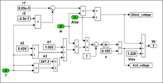
$v_{r e v}=1.5306-1.9836 \times 10^{-3} * T-1.3862 * 10^{-8} *$$\mathrm{T}^{2}+1.7194 * 10^{-4} * \mathrm{~T} * \ln (\mathrm{T})+\frac{0.0868}{\mathrm{~T}}$ (12)
However, during the electrolysis process, the voltage requirement increases due to the activation over voltage and ohmic overvoltage. Thus, the voltage required is equal to [79-80]:
$v_{e}*=v_{r e v}+v_{act}+v_{ohm}$ (13)
where:
$v_{act}=\mathrm{s} \times \log \left(\frac{\mathrm{K}_{1}+\frac{\mathrm{K}_{2}}{\mathrm{~T}_{\mathrm{e}}}+\frac{\mathrm{K}_{3}}{\mathrm{~T}_{\mathrm{e}}}}{\delta} \mathrm{I}_{\mathrm{e}}+1\right)$ (14)
$v_{ohm}=\frac{\varepsilon_{1}+\varepsilon_{1} \mathrm{~T}_{\mathrm{e}}}{\delta} \mathrm{I}_{\mathrm{e}}$ (15)
The Faraday efficiency and the total hydrogen production rate (mol/s) are given by [26-27]:
$\eta_{F}=\frac{\left(\frac{\mathrm{I}_{\mathrm{e}}}{\delta}\right)^{2}}{\chi_{1}+\left(\frac{\mathrm{I}}{\delta}\right)^{2}} \chi_{2}$ (16)
$\varphi_{\mathrm{H}_{2}}=\eta_{\mathrm{F}} \frac{\mathrm{N}_{\mathrm{C}} \mathrm{I}_{\mathrm{e}}}{\mathrm{zF}}$ (17)
The equation (17) can be expressed in unit Nm3/h as follows:
$\lambda_{\mathrm{H}_{2}}=\varphi_{\mathrm{H}_{2}} * 3600 * 0.022414$ (18)
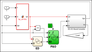
In order to evaluate the PV-Alkaline Electrolyzer, the whole system including the PV generator fed by the DC-DC converter controlled using the proposed stateflow variable step size P&O based MPPT and the Alkaline Electrolyzer have been implemented using the Matlab/Simulink environment. Tables 1 to 3 give the parameters used to implement the models; while Figures 3 to 6 shows the developed Simulink models.
Table. 1 Constants Parameters for the Electrolyzer
|
Constant Parameters |
Sym. |
Units |
Value |
|
Overall current across the cell |
Ie |
A |
- |
|
Reversible voltage |
urev |
V |
1.229 |
|
Temperature of the electrolyzer |
Te |
°C |
- |
|
Area of Electrode |
d |
m2 |
0.25 |
|
Faraday’s Constant |
F |
C/mol |
96485 |
|
Number of Electrons |
z |
/ |
2 |
|
Coeff. for overvoltage on electrodes |
S |
V |
0.185 |
|
Coeff. for overvoltage on electrodes |
K1 |
A-1m2 |
1.002 |
|
K2 |
A-1m2C |
8.424 |
|
|
K3 |
A-1m2C2 |
247.3 |
|
|
Parameters related to ohmic resistance of electrolyte |
e1 |
Ω m2 |
8.05e-5 |
|
e2 |
Ω m2C |
-2.5e-7 |
Table 2. Parameters of BP SX150S solar module.
|
Parameter |
Value |
|
Maximum Power (Pmax) (W) |
150 |
|
Voltage at Pmax (Vmp) (V) |
34.5 |
|
Current at Pmax (Imp) (A) |
4.35 |
|
Short circuit current (Isc) (A) |
4.75 |
|
Open-circuit voltage (Voc) (V) |
43.5 |
|
Temp. Coefficient of Isc (%/°C) |
0.065 |
|
Temp. Coefficient of Voc (%/°C) |
0.038 |
|
NOCT (°C) |
47 |
Table. 3 Faraday Efficiency Parameters.
|
Constant Parameters |
Units |
Value |
||
|
Temperatures |
°C |
40 |
60 |
80 |
|
c1 |
mA2cm-4 |
150 |
200 |
250 |
|
c2 |
- |
0.99 |
0.985 |
0.98 |
Fig. 3 Simulink model of PV module BP-SX150S.
Fig. 4 State-Flow chart of P&O algorithm.
Fig. 5 Simulink model of electrolyzer cell voltage.
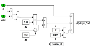
Fig. 6 Simulink model of Faraday efficiency and amount of hydrogen.
To analyse the proposed PV-Alkaline electrolyzer, we consider the following curves:
3.1 PV Characteristics
PV curves correspond to PV module BP-SX150S characteristics in respect of irradiation and temperature change. Figures 7 to 10 show I-V and P-V characteristics.
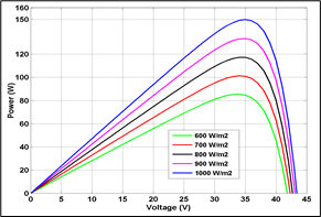
Figures 7 and 8 show the I-V voltage characteristics and P-V power characteristics of the PV module for different irradiation levels (600, 700, 800, 900 and 1000 W/m2) at constant temperature (T =25°C), respectively. Through the Figure 7, we can see how the curves move in the vertical direction much more than they move horizontally. Therefore, the changes in the irradiation doesn't affected the module voltage, in which the open circuit voltage increases slightly while the short circuit current increases very sharply since the short circuit current is a linear function of the irradiation. As can be observed from the curve of power-voltage (Figures 8), the output power is raising with the increasing of the irradiation. In general, there is a direct correlation between increasing the level of irradiation and the output power, and this leads to the increasing of the maximum output power.
Fig. 7 I-V characteristics under variable irradiations.
Fig. 8 P-V Characteristics under variable irradiations.
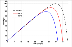
Figures 9 and 10 show the effect of temperature variation (T= 25, 50, 75°C) at constant solar irradiation (1000 W/m2) on I-V and P-V characteristics respectively. From figure 9, we can see the curve is moving strongly along the horizontal voltage axis other than that it is moving slightly along the vertical current axis. Indeed, it can be observed that with the temperature increasing, the short circuit current rises slightly and the open circuit voltage reduces strongly. Therefore, the temperature changes directly affect the voltage output, which in turn the significant immediately impacts the maximum power output in the same way. Generally speaking, the photovoltaic module operates low efficiently, in which the maximum output power reduces with increasing temperature as shown in Figure 10.
Fig. 9 I-V characteristics under variable temperatures.
Fig. 10 P-V characteristics under variable temperatures.
3.2 Electrolyzer Characteristics
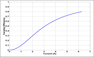
The alkaline electrolyzer Ie-ue and Ie-hF curves are presented in Figures 11 and 12. Figure 11 represent the Ie-ue curve of the alkaline electrolyzer. At the beginning, the electrolysis reaction does not take place when the cell voltage is very small with cell current is null. After that, the cell current becomes increasing, in which the evolution of the cell voltage with the current is logarithmic. In this range corresponding to low-current values, activation phenomena predominate. As the current increases, the curve becomes linear and the ohmic overvoltages predominate. The cell voltage increases and the power supplied to the cell is always greater than the minimum required by the electrochemical process and then the electrolysis reaction takes place. While Figure 12 show the Faraday’s efficiency curve Ie-hF. The evaluation of the amount of hydrogen generated related to the Faraday efficiency. From Figure, we can see the Faraday’s efficiency increases as the current increased. Due to the influence of parasitic current loss in Faraday efficiency, it is also called current coefficient. However Faraday’s efficiency increases sharply to a maximum of about 80% coinciding with the increase in current.
Fig. 11 Electrochemical characteristic of the electrolyzer $I_{e}-v_{e}$.
Fig. 12 Electrochemical characteristic of the electrolyzer $I_{e}-\eta_{F}$.
3.3 Coupling Characteristics
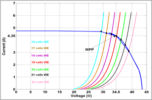
Fig. 13 below shows the current-voltage curves for both systems PV at 1000W/m2 indirectly coupled with the different number of water alkaline electrolyzer cells between 16 to 22 cells operating at temperature 40°C. Intersection points of these two characteristics represent the operating point when the stack electrolyzer (number of cells connected in series and parallel) is indirectly coupled to the PV system.
Fig. 13 I-V Characteristics of PV and Alkaline Electrolyzer at 1000W/m2.
Table 4 shows the maximum power, MPPT efficiency and hydrogen production rate using the indirect Coupling PV with Alkaline Electrolyzer.
Table 4. Indirect Coupling PV with Alkaline Electrolyzer
|
Nb. of Cell of Water Electr. |
V (V) |
I (A) |
Output Power (W) |
MPPT eff. (%)* |
H2 Prod. rate (Nm3/h) |
|
16 |
29.41 |
4.7 |
138.22 |
92.14 |
0.033 |
|
17 |
31.17 |
4.58 |
142.75 |
95.16 |
0.035 |
|
18 |
32.96 |
4.53 |
149.31 |
99.54 |
0.037 |
|
19 |
34.64 |
4.32 |
149.64 |
99.76 |
0.040 |
|
20 |
36.24 |
4.06 |
147.13 |
98.06 |
0.041 |
|
21 |
37.65 |
3.64 |
137.05 |
91. 36 |
0.043 |
|
22 |
38.88 |
3.15 |
122.47 |
81.64 |
0.046 |
*MPPT efficiency = Actual PV output/Maximum PV output
From Table 4 we can observe the highest power of the coupling PV-electrolyzer is achieved with 19 cells configuration. In this case, the MPPT efficiency is 99.76% while the hydrogen production rate is around 0.040 m3/h.
3.4 Polarization Characteristics
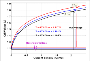
Polarization curves have been analyzed using different level of temperatures: 40°C, 60°C and 80°C to evaluate the temperature effect on the electrolysis characteristics; as a consequence of the temperature effect on the activation and ohmic overvoltage. Table. 5 give the values of reversible voltage at different temperature.
Table. 5 Energy Gibbs and Reversible Voltages at Different Temperature
|
T(K) |
$\Delta G$ (kJ/mol) |
$v_{r e v}$ (Volt) |
|
298 |
237,45 |
1.229 |
|
313 |
235,02 |
1.217 |
|
333 |
231,83 |
1.201 |
|
353 |
228,67 |
1.185 |
From Table 5, we can see the inverse relationship between T and urev: the reversible voltage decreases with temperature increases. At standard temperature and pressure (298°K and 1.0325 bar), Gibbs energy $\Delta G$ is 237.45KJ/mol. This energy decreases with temperature increases. Accordingly, the minimum voltage required to boost the process water electrolysis is affected by temperature changes.
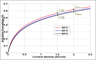
Fig.14 shows the variation of activation losses regarding temperature as a function of current density.
Fig. 14 Polarization curve activation overvoltage.
From Fig. 14 we can see that activation losses decrease with the increasing of temperature. For high current density, the losses are 0.03V higher for 40°C compared to 80°C.
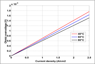
The ohmic overvoltage is due to the immigration of the ions through the electrolyte. The increase of the temperature reduces the electrolyte resistance and therefore reduces as consequence the ohmic overvoltage. The relationship between the losses and current density is linear (as seen in eq. 15) as shown in the Fig. 15.
Fig. 16 shows the effect of the rempartre on the polarization curve. The operating cell voltage starts to increase slowly from the value of reversible voltage at low current density. At current density 1.5A/cm2 the voltage drop is arround 0.064V.
Fig. 15 Polarization curve ohmic overvoltage.
Fig. 16 Polarization curve of $I_{e}-v_{e}$.
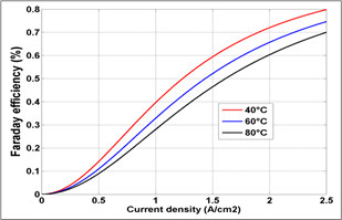
Figures 17 and 18 show the faraday efficiency and production rate of hydrogen under different temperature levels.
Fig. 17 Polarization curve faraday efficiency.
Fig. 18 Production hydrogen as function current density.
In this paper, indirectly coupling of PV system with alkaline electrolyzer for hydrogen production has been implemented and investigated. Both systems have been studied under Matlab/Simulink environment by the development of the two corresponding models, PV and Alkaline electrolyzer, respectively. The developed models allow us the analysis of current-voltage characteristics for both systems PV and Electrolyzer, individually as well as in hybrid coupled model PV-Alkaline Electrolyzer. In addition, the developed models permit the assessment of the principal parameters affecting the performance of the alkaline electrolyzer. The future work will focus on the experimental validation of the developed models.
The Algerian Ministry of Higher Education and Scientific Research supported this research (Research PRFU Project A01L07UN190120180005).
|
Ipv |
The current of the PV cell (A). |
|
Ip |
The light-generated photocurrent (A). |
|
Is |
The reverse saturation current of the diode (A). |
|
Isc |
The Short circuit current (A). |
|
q |
The electron charge (C). |
|
Vpv |
The voltage of the PV cell U (V). |
|
Voc |
The Open-circuit voltage (V). |
|
Rs |
The series resistor of the PV cell (Ω). |
|
Rsh |
The shunt resistor of the PV cell (Ω). |
|
N |
The diode ideality factor. |
|
K |
The Boltzman’s constant. |
|
T |
The temperature (K). |
|
Ki |
The cell short circuit-current temperature coefficient. |
|
Tref |
The nominal reference temperature (K). |
|
S |
The irradiation (W/m2). |
|
Eg |
The band-gap energy of semiconductor |
|
ED |
The new step size; |
|
N |
The Scaling factor. |
|
$v_{rev}$ |
The reversible voltage (V). |
|
$v_{act}$ |
The activation overvoltage (V). |
|
$v_{ohm}$ |
The ohmic overvoltage (V). |
|
$\Delta \mathrm{G}$ |
The Gibbs free energy change J/mol. |
|
F |
The faraday’s constant C/mol. |
|
z |
The number of electron. |
|
$\eta_{\mathrm{F}}$ |
The Faraday efficiency (%). |
|
$\varphi_{\mathrm{H}_{2}}$ |
The total hydrogen production (mole/s). |
|
$\delta$ |
The area of electrode (m2). |
|
S |
The Coeff. for overvoltage on electrodes (V). |
|
Ki=1,2, 3 |
The Coeff. for overvoltage on electrodes. |
|
$\varepsilon_{1}$ |
The Parameters related to ohmic (Ω m2). |
|
$\varepsilon_{2}$ |
The resistance of electrolyte (Ω m2C). |
|
PV |
Photovoltaic. |
|
FC |
Fuel Cell. |
|
MPPT |
Maximum Power Point Tracking. |
|
MPP |
Maximum Power Point. |
|
PEM |
Proton Exchange Membrane Electrolyzer. |
|
SOE |
Solid Oxide Electrolyzer. |
|
DC |
Direct Current. |
|
P&O |
Perturbation and Observation. |
|
IC |
Incremental Conductance. |
|
FLC |
Fuzzy Logic Control. |
|
SMC |
Sliding Mode Control. |
|
ESC |
Extremum Seeking Control. |
|
ANN |
Artificial Neural Network. |
|
PSO |
Particle Swarm Optimization. |
[1] L. Wenjia, H. Wang, Y. Hao, A PVTC system integrating photon-enhanced thermionic emission and methane reforming for efficient solar power generation, Science Bulletin, 62, 2017: 1380-1387.
[2] Y. Uzun; E. Kurt, H. Kurt, Explorations of displacement and velocity nonlinearities and their effects to power of a magnetically-excited piezoelectric pendulum, Sensors Actuat A Phys, 224, 2015: 119-130.
[3] H. Wang, B. Wang, X. Qi, J. Wang, R. Yang, D. Li, X. Hu, Innovative non–oxidative methane dehydroaromatization via solar membrane reactor, Energy, 216, 2016: 119265.
[4] B. Paridaa, S. Iniyanb, R. Goic ‘’ A review of solar photovoltaic technologies’’ Renewable and Sustainable Energy Reviews, 15, 2011: 1625-1636.
[5] N. S. Lewis, Research opportunities to advance solar energy utilization, 351, 2016: 353-364.
[6] S. Guo, Q. Liu, J. Sun, H. Jin, A review on the utilization of hybrid renewable energy, Renewable and Sustainable Energy Reviews, 91, 2018: 1121-1147.
[7] M. Hosenuzzaman, N. A. Rahim, J. Selvaraj, M. Hasanuzzaman, A. B. M. A. Malek, A. Nahar, Global prospects, progress, policies, and environmental impact of solar photovoltaic power generation, Renewable and Sustainable Energy Reviews, 41, 2015 : 284-297.
[8] S. A. Kalo”girou ‘’Chapter nine photovoltaic systems’’ Solar Energy Engineering, 2009, 469-519, https://doi.org/10.1016/B978-0-12-374501-9.00009-1.
[9] C. Robles Algarín, J. Taborda Giraldo and O. Rodríguez Álvarez, Fuzzy Logic Based MPPT Controller for a PV System, Energies 2017, 10(12), 2036.
[10] P. G. V. Sampaio, M. O. A. González ‘’ Photovoltaic solar energy: Conceptual framework’’ Renewable and Sustainable Energy Reviews, 2017, Vol 74, P 590-601
[11] J. H. R. Enslin, D. B. Snyman ‘’Combined low-cost, high-efficient inverter, peak
power tracker and regulator for PV application’’ IEEE Trans Power Electron, 1991, Vol 6, P 73-82.
[12] H. Wang, Y. Hao, H. Kong ‘’ Thermodynamic study on solar thermochemical fuel production with oxygen permeation membrane reactors’’ Int. J. Energy Res, 2015, Vol 39, P 1790-1799
[13] Stadler I. Storage and interconnected renewable energy systems. Stories Project Workshop, http://www. Stories project.eu/docs/Storage_and_interconnected_RES_U_of_Applied_Science_Cologne_Dubrovnilk.pdf; 1-2 October 2009. Dubrovnik, Croatia.
[14] M. A. Rosen, S. Koohi-Fayegh ‘’the prospects for hydrogen as an energy carrier: an overview of hydrogen energy and hydrogen energy systems’’ Energy Ecology and Environment, 2016, Vol 1, P 10-29.
[15] A. Awasthi, K. Scott, S. Basu ‘’Dynamic modeling and simulation of a proton exchange membrane electrolyzer for hydrogen production’’ International Journal of Hydrogen Energy, 2011, Vol 36, P 14779-14786.
[16] H. Idriss, M. Scott, V. Subramani ‘’Introduction to hydrogen and its properties’’ Compendium of Hydrogen Energy. http://dx.doi.org/10.1016/B978-1-78242-361-4.00001-7.
[17] K. Christopher, R. Dimitrios ‘’ A review on exergy comparison of hydrogen production methods from renewable energy sources’’ Energy Environ. S ci., 2012, Vol 5, P 6640-6651.
[18] L. Xu, Y. Wang, S. A. A. Shah, H. Zameer, Y. A. Solangi, G. D. Walasai, Z. A. Siyal ‘’ Economic Viability and Environmental Efficiency Analysis of Hydrogen Production Processes for the Decarbonization of Energy Systems’’ Processes 2019, Vol 7, 494. https://doi.org/10.3390/pr7080494.
[19] C. M. Kalamaras, A. M. Efstathiou ‘’ Hydrogen Production Technologies: Current State and Future Developments’’ Hindawi Publishing Corporation Conference Papers in Energ y, 2013, http://dx.doi.org/10.1155/2013/690627.
[20] K. Nath, D. Das ‘’Production and storage of hydrogen: present scenario and future perspective’’ Journal Scientific & Industrial Research, 2007, 2007, Vol 66, P 701-709.
[21] H. Wang, Y. Hao, H. Kong ‘’Thermodynamic study on solar thermochemical fuel production with oxygen permeation membrane reactors’’ International Journal Energy of Research, 2015, Vol 39, P 1790-1799.
[22] H. Wang, M. Liu, H. Kong, Y. Hao ‘’Thermodynamic analysis on mid/low temperature solar methane steam reforming with hydrogen permeation membrane reactors’’ Applied Thermal Engineering, 2018, https://doi.org/10.1016/j.applthermaleng.2018.03.030.
[23] Z. Bai, Q. Liu, J. Lei, H. Hong, H. Jin ‘’New solar-biomass power generation system integrated a two-stage gasifier’’ Applied Energy 2017, Vol 194, P 310–319.
[24] H. Kong, Y. Hao, H. S. Wang ‘’A solar thermochemical fuel production system integrated with fossil fuels’’ Applied Thermal Energy, 2016, Vol 108, P 958-966.
[25] E. Kırtay ‘’ Recent advances in production of hydrogen from biomass’’ Energy Conversion and Management, 2011, 52, P 1778-1789.
[26] A. T. Najafabadi, F. Taghipour ‘’ Physicochemical impact of zeolites as the support for photocatalytic hydrogen production using solar-activated TiO2-based nanoparticles’’ Energy Conversion and Management, 2014, 82, P 106-113.
[27] H. Nami, F. Mohammadkhani, F. Ranjbar ‘’Utilization of waste heat from GTMHR for hydrogen generation via combination of organic Rankine cycles and PEM electrolysis’’ Energy Conversion and Management, 2016, Vol 127, P 589-598.
[28] H. Wang, W. Li, T. Liu, X. Liu, X. Hu ‘’ Thermodynamic analysis and optimization of photovoltaic/thermal hybrid hydrogen generation system based on complementary combination of photovoltaic cells and proton exchange membrane electrolyzer’’ Energy Conversion and Management, 2019, Vol 183, P 97-108.
[29] H. Ishaq, I. Dincer, G. F. Naterer ‘’Development and assessment of a solar, wind and hydrogen hybrid trigeneration system’’ International Journal of Hydrogen Energy, 2018, Vol 43, P 23148-23160.
[30] H. Wang, H. Kong, Z. Pu, Y. Li, X. Hu ‘’ Feasibility of high efficient solar hydrogen generation system integrating photovoltaic cell/photon-enhanced thermionic emission and hightemperature electrolysis cell’’ Energy Conversion and Management, 2020, Vol 210, 112699.
[31] B. Wang, H. Kong, H. Wang, Y. Wang, X. Hu ‘’ Kinetic and thermodynamic analyses of mid/lowtemperature ammonia decomposition in solardriven hydrogen permeation membrane reactor’’ International Journal of Hydrogen Energy, 2019, Vol 44, P 26874-26887.
[32] P. Kumar, A. Gupta, R. Kumar Pachauri, K. Yogesh Chauhan, Utilization of Energy Sources in Hybrid PV/FC Power Assisted Water Pumping System, Int. Conf. on Computational Intelligence & Communication Technology, 13-15 Feb., 2015.
[33] N. Bigdeli ‘’ Optimal management of hybrid PV/fuel cell/battery power system: A comparison of optimal hybrid approaches’’ Renewable and Sustainable Energy Reviews, 2015, Vol 42, P 377-393.
[34] C. Lebreton, M. Benne, C. Damour, N. Yousfi-Steiner, Brigitte Grondin-Perez, Daniel Hissel, Jean-Pierre Chabriat, Fault Tolerant Control Strategy applied to PEMFC water management, int. Journal of hydrogen energy, 2015:10636-10646.
[35] W. Yun, K. S. Chen, J. Mishler, S. C. Cho, X. C. Adroher ‘’ A review of polymer electrolyte membrane fuel cells: Technology, applications, and needs on fundamental research’’ Applied Energy, 2011, Vol 88, P 981-1007.
[36] S. Zhang, X-Z Yuan, J. N. C. Hin, H. Wang, K. A. Friedrich, M. Schulze ‘’A review of platinum-based catalyst layer degradation in proton exchange membrane fuel cells’’ Journal Power Sources 2009, Vol 194, P 588-600.
[37] S. Zhanga, X. Yuana, H. Wang, W. Merida, H. Zhu, J. Shen, S. Wu, Jiujun Zhang ‘’ A review of accelerated stress tests of MEA durability in PEM fuel cells. International Journal of Hydrogen Energy, 2009, Vol 34, P 388-404.
[38] C. Gittleman, D. M. S. Jorgensen, J. Waldecker, S. Hirano, M. Mehall ‘’Automotive fuel cell R&D needs. In: DOE fuel cell pre-solicitation workshop’’ Department of Energy, Lakewood, Colorado; 2010.
[39] B. Shabani, M. Hafttananian, Sh. Khamani, A. Ramiar, A. A. Ranjbar ‘’ Poisoning of proton exchange membrane fuel cells by contaminants and impurities: Review of mechanisms, effects, and mitigation strategies’’ Journal of Power Sources, 2019, Vol 427, P 21-48.
[40] J. J. Baschuk, L. Xianguo ‘’ Carbon monoxide poisoning of proton exchange membrane fuel cells’’ International Journal of Hydrogen Energy, 2001, Vol 25, P 695-713.
[41] M. Carmo, D. L. Fritz, J. Mergel, D. Stolten ‘’ A comprehensive review on PEM water electrolysis’’ International Journal of Hydrogen Energy, 2013, Vol 38, P 4901-4934.
[42] R. Bhattacharyya, A. Misra, K. C. Sandeep ‘’ Photovoltaic solar energy conversion for hydrogen production by alkaline water electrolysis: Conceptual design and analysis’’ Energy Conversion and Management, 2017, Vol 133, P 1-13.
[43] Ni. Meng, K. H. M. Leung, K. Sumathy, Y. C. D. Leung ‘’Potential of renewable hydrogen production for energy supply in Hong Kong’’ International Journal of Hydrogen Energy, 2006, Vol 31, P 1401-1412.
[44] A. Mohammadi, M. Mehrpooya ‘’ A comprehensive review on coupling different types of electrolyzer to renewable energ y sources’’ Energy, 2018, Vol 158, P 632-655.
[45] A. Ursua, L. M. Gandia, P. Sanchis "Hydrogen Production From Water Electrolysis: Current Status and Future Trends" in Proceedings of the IEEE, 2012, Vol 100, P 410-426, doi: 10.1109/JPROC.2011.2156750.
[46] R. Garcia-Valverde, N. Espinosa, A. Urbina ‘’Optimized method for photovoltaic-water electrolyser direct coupling’’ International Journal of Hydrogen Energy, 2011, Vol 36, P 10574-10586.
[47] E. Bilgen ‘’Solar hydrogen from photovoltaic–electrolyzer systems’’ Energy Conversion Management, 2001; Vol 42, P 1047-1057.
[48] D. Shapiro, J. Duffy, M. Kimble, M. Pien ‘’Solar-powered regenerative PEM electrolyzer/fuel cell system’’ Solar Energy, 2005, Vol 79, P 544-550.
[49] L. G. Arriaga, W. Martinez, U. Cano, H. Blud ‘’Direct coupling of a solar–hydrogen system in Mexico’’ International Journal of Hydrogen Energy, 2007, Vol 32, P 2247-2252.
[50] B. Paul, J. Andrews ‘’Optimal coupling of PV arrays to PEM electrolyzers in solar hydrogen systems for remote area power supply’’ International Journal of Hydrogen Energy, 2008, Vol 33, P 490-498.
[51] R. E. Clarke, S. Giddey, F. T. Ciacchi, S. P. S. Badwal, B. Paul, J. Andrews ‘’Direct coupling of an electrolyzer to a solar PV system for generating hydrogen’’ International Journal of Hydrogen Energy, 2009; Vol 34, P 2531-2542.
[52] T. L. Gibson, N. A. Kelly ‘’Predicting efficiency of solar powered hydrogen generation using photovoltaic-electrolysis devices’’ International Journal of Hydrogen Energy, 2010, Vol 35, P 900-911.
[53] O. Atlam, F. Barbir, D. Bezmalinovic ‘’A method for optimal sizing of an electrolyzer directly connected to a PV module’’ International Journal of Hydrogen Energy, 2011, Vol 36, P 7012-7018.
[54] H. Solmecke, O. Just, D. Hackstein ‘’Comparison of solar hydrogen storage systems with and without power-electronic DC/DCconverters’’ Renewable Energy, 2000, Vol 19, P 333-338.
[55] E. Bilgen ‘’Solar hydrogen from photovoltaic-electrolyzer systems’’ Energy Conversion and Management, 2001, Vol 42, P 1047-1057.
[56] G. E. Ahmad, E. T. El Shenawy ‘’Optimized photovoltiac system for hydrogenproduction’’ Renewable Energy, 2006, Vol 31, P 1043-1054.
[57] T. Tafticht, K. Agbossou, M. L. Doumbia ‘’ A new MPPT method for photovoltaic systems used for hydrogen production’’ The International Journal for Computation and Mathematics in Electrical and Electronic Engineering, 2007, Vol 26, P 62-74.
[58] R. Garcia-Valverde, C. Miguel, R. Martinez-Bejar, A. Urbina ‘’Optimized photovoltaic generatorewater electrolyser
coupling through a controlled DC-DC converter’’ International Journal of Hydrogen Energy, 2008, Vol 33, P 5352-5362.
[59] A. A. Nafeh ‘’Hydrogen production from a PV/PEM electrolyzer system using a neural-network-based MPPT algorithm’’ Int. J. Numer. Model, 2011, Vol 24, P 282-297.
[60] Y. N. Anagreh, A. Alnassan, A. Radaideh ‘’ High Performance MPPT Approach for Off-Line PV System Equipped With Storage Batteries and Electrolyzer’’ Int. Journal of Renewable Energy Development, 2021, Vol 10, P 507-515.
[61] A. O. Baba, G. Liu, X. Chen ‘’ Classification and Evaluation Review of Maximum Power Point Tracking Methods’’ Sustainable Futures, 2020, Vol 2, 100020.
[62] M. Mao, L. Cui, Q. Zhang, K. Guo, L. Zhou, H. Huang ‘’ Classification and summarization of solar photovoltaic MPPT techniques: A review based on traditional and intelligent control strategies’’ Energy Reports, 2020, Vol 6, P 1312-1327.
[63] R. Garraoui, M. Ben Hamed and L. Sbita, MPPT controller for a photovoltaic power system based on fuzzy logic, 10th Int. Multi-Conf. on Systems on Signals & Devices (SSD), 18-21 Mar. 2013.
[64] N. Moubayed and R. Outbib, Energy Management for a PEMFC-PV hybrid system’’ Energy Conversion and Management 82, 2014:154–168.
[65] E. Elgharboui, A.Essadki and N. Tamou, MPPT Commands for a photovoltaic generator using the Incremental Conductance Method and the fuzzy logic command, International Conference on Electrical Sciences and Technologies in Maghreb (CISTEM), 3-6 Nov. 2014.
[66] N. Tlili, B. Neily and F. Ben Salem, Modeling and simulation of hybrid system Coupling a Photovoltaic Generator, a PEM Fuel Cell and an Electrolyzer (Part I), 11th International Multi-Conference on Systems, Signals & Devices (SSD14) , 11-14 Feb., 2014.
[67] O. Palizban and S. Mekhilef, Modeling and Control of Photovoltaic Panels Base Perturbation and Observation MPPT Method, International Conference on Control System, Computing and Engineering, 25-27 Nov., 2011.
[68] L. El Bahir and T. Hassboun, Accurate Maximum Power Point Tracking Algorithm Based on a Photovoltaic Device Model, International Journal of Photoenergy 2017:1-10.
[69] M. I. Arteaga Orozco, J. R. Vázquez, P. Salmerón, S. P. Litrán, F. J. Alcántara ‘’ Maximum power point tracker of a photovoltaic system using sliding mode control, Int. Conf. on Renewable Energies and Power Quality (ICREQ’09), 15-17 Apr. 2009.
[70] N. Altin, The Type-2 Fuzzy Logic Controller-Based Maximum Power Point Tracking Algorithm and the Quadratic Boost Converter for Pv System,Journal of Elec Materi (2018) 47: 4475.
[71] A. Harrag and H. Bahri, Novel Neural Network IC-based Variable Step Size Fuel Cell MPPT Controller - Performance, Efficiency and Lifetime Improvement, International Journal on Hydrogen Energy 42(5), 2017: 3549-3563.
[72] A. Harrag and S. Messalti, How fuzzy logic can improve PEM fuel cell MPPT performances, International Journal on Hydrogen Energy, 43, 2018:537-550.
[73] S. Zhou, L. Kang, J. Sun, G. Guo, B. Cheng, B. Cao and Y. Tang, A Novel Maximum Power Point Tracking Algorithms for Stand-alone Photovoltaic System, A novel maximum power point tracking algorithms for stand-alone photovoltaic system, International Journal of Control, Automation and Systems, 8(6), 2010:1364-1371.
[74] S. Abdourraziq, R. El Bachtiri, A Perturb and Observe Method using Dual Fuzzy Logic Control for Resistive Load, Recent Advances in Environmental Science and Biomedicine, 2015:107-112.
[75] R. Boudries, A. Khellaf, A. Aliane, L. Ihaddade and F. Khida, PV system design for powering an industrial unit for hydrogen production, international journal of hydrogen energy, 37(29), 2014: 14503-15292.
[76] A. Beainy, N. Karami and N. Moubayed, Simulink Model for a PEM Electrolyzer Based on an Equivalent Electrical Circuit, 2nd Renewable Energy for Developing Countries-REDEC, Nov 2014.
[77] F. Z. Aoualia, M. Becherifb, A.Tabanjatb, M. Emzianec, K. Mohammedia , S. Krehid, A. Khellaf, Modelling and experimental analysis of a PEM electrolyzer poweredby a solar photovoltaic panel, Energy Procedia, 62, 2014: 714-722.
[78] A.S Tijani, N.A Binti Yusup and A. H. Abdol Rahim, Mathematical modelling and simulation analysis of advanced alkaline electrolyzer system for hydrogen production, 2nd Int Conf. on System-Integrated Intelligence: Challenges for Product and Production Engineering, 2014: 798-806.
[79] A. Khalilnejad, A. Sundararajan, A.I. Sarwat, Optimal design of hybrid wind/photovoltaic electrolyzer for maximum hydrogen production using imperialist competitive algorithm, Journal of Modern Power Systems and Clean Energy, 6(1), 2018: 40-49.
[80] A. Khalilnejad, A. Sundararajan, A. Abbaspour and A. Sarwat, Optimal Operation of Combined Photovoltaic Electrolyzer Systems, Energies 2016, 9(5), 332.