Boudia Assam | Messalti Sabir | Harrag Abdelghani
© 2020 IIETA. This article is published by IIETA and is licensed under the CC BY 4.0 license (http://creativecommons.org/licenses/by/4.0/).
OPEN ACCESS
Although the great advance in power system production and operation, storage energy technologies and its control techniques can be considered as one of the most important and critical topics of power companies , government and consumers, especially when the power system containing renewable source and storage system simultaneously. In this paper, a novel electrical grid structure including photovoltaic system and storage system based on Superconducting Magnetic Energy Storage (SMES) has been proposed and investigated. The SMES produced power is injected in power system during specific time or when it required. Two control strategies for exchanged power Grid- SMES have been proposed and analyzed, the first uses sliding mode and the second uses field oriented control based on PI controller, also the injected SMES power is controlled by PID controller. In addition, the photovoltaic system operates at the MPP employing PID MPPT method. The proposed control strategies have been tested successfully in which many scenarios have been studied: standby and discharging of SMES, injection of SMES storage energy for variable and constant load and control of grid containing PV system. In addition, a comparative study of exchanged power Grid- SMES control using Sliding mode and field oriented control based on PI controller has been presented and discussed.
Grid-PV-SMES, power integration, sliding Mode
The last years have seen gradually an expansion on application in the storage energies, through all storage energies, the SMES (Superconducting Magnetic Energy Storage) is placed in this group, the SMES is coil which is in a superconducting state at cryogenic temperature, this means that the energy losses during the operation is almost zero[1-5], the SMES is an electrical energy that stores the energy in the magnetic field ,it has the Ability to rapidly release stored energy, very high storage energy, Quick to recharge (millisecond) with high efficiency and almost infinite cycle life, also the SMES used to control the active and reactive power, used to the transmission and distribution system stability and stabilize system frequency[6-8].
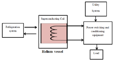
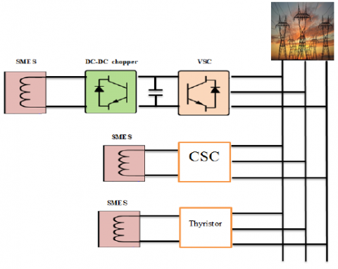
The SMES can stores the energy directly from electrical power, because the SMES resistance almost equal zero and the mobility is very high at very low temperature, which called critical temperature, the SMES unit consists of three main components: superconducting unit, cryogenic refrigerator and vacuum-insulated vessel fig 1, the SMES is connected to the grid in three modes as is shown in fig 2, voltage source converter (VSC)[9-12], current source converter (CSC)[13-15], and thyristor[16, 17].
In VSC mode, the SMES energy is controlled by DC-DC chopper in the absorbing or injection power, in ref [18] the authors charge and discharge the SMES using dc-dc chopper which is controlled by proportional and integral (PI) controller, in ref [8] fuzzy logic controller (FLC)is applied on the SMES charging and discharging of the SMES active and reactive powers. The FLC is controlled by two inputs: wind speed and SMES current variations.
To support the increasing energy demand and the development of renewable energies (solar and wind,…etc) whose production is variable, non-controllable and decentralized, hence, increasing the storage capacity of electricity is a necessity. However, there are still many technical and economic problems that reduce thedeployment of new storage technologies. Significant research efforts are underway around the world. In this document, power grids containing photovoltaicsystem and storage system based on Superconducting Magnetic Energy System (SMES) has been proposed and analyzed for different possible scenarios and load levels.
Figure 1. Functional diagram of the SMES system[19]
Figure 2. SMES applications Modes
The most applications of the SMES are: SMES is used to the transmission and distribution system stability[20], control of voltage based on active and reactive power[21] and smooth the wind farm output by absorbing or providing realpower [22], SMES can respond very quickly to the active and reactive power demand [22, 23] and stabilize system frequency, the SMES is characterized by its rapid response (milliseconds)[24]and long life cycle[25]compared to other energy storage systems, it has a very high storage efficiency.
The energy and power are expressed as in equations (1) and (2):
$E=\frac{1}{2} L i^{2}$ (1)
$P=\frac{d E}{d t}$ (2)
Where ‘i’ is the current through the coil and ‘L’ is the superconducting coil inductance, the SMES stores the energy as circulating current, and provide the energy with instantaneous response.
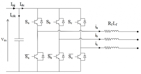
Voltage source converter is used to accomplish the transformation of power between utility three-phase alternating current and the DC bus. It consists on three-phase –insulated-gate bipolar transistor (IGBT) full-bridge with three input inductors (L) and resistor (R) on the ACside and a filter capacitor (C) on the DC side. In order to control the power flow of the system, the input inductors’ currents are accurately controlled following the power demand P and Q as shown in Figure 3.
Figure 3. Topological configuration of VSC
2.1. Control of injected power into grid based using field oriented control
The diagram of the functional control strategy of the voltage source converter is presented in figure 4. The directions of the voltages Vdref and Vqref, generate the phase and the amplitude of the useful voltage. The Park transformation block (3S / 2R) transforms the three-phase current Ia, Ib and Ic from the stationary form to the synchronous form. Then Id and Iq represent the active and reactive component of the converter respectively. The reference voltage in the input of the voltage source converter is also given in equations 3, 4 and 5.
Figure 4. Voltage source converter control based on PI controller
$u_{c d, q}=P I\left(i_{d, q r e f}-i_{d, q}\right)$ (3)
ucd,q the voltage calculated using PI controller, which control the error between the references currents id,qref and the measured currents id,q. Hence, the output reference voltage of voltage source current VSC based on Park transformation are expressed by
$\left\{\begin{array}{l}V_{d r e f}=e_{d}+u_{c d}-L_{f} w i_{q} \\ V_{q r e f}=e_{q}+u_{c q}+L_{f} w i_{d}\end{array}\right.$ (4)
Vd,qref is the calculated reference voltage.
ed and eq are the park transformation voltages of the grid common connection points.
Lf represents the coupling inductance of a phase of the filter between the VSC and the grid.
$\left[\begin{array}{c}i_{\text {dref}} \\ i_{\text {qref}}\end{array}\right]=\frac{1}{e_{d}^{2}+e_{q}^{2}}\left[\begin{array}{cc}e_{d} & e_{q} \\ -e_{q} & e_{d}\end{array}\right]\left[\begin{array}{c}P_{\text {ref}} \\ Q_{\text {ref}}\end{array}\right]$ (5)
where Pref and Qref are the references of the active and reactive powers.
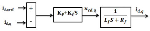
The id,q current regulation loop are based on PI regulators to calculated ucd,q, as is shown in figure 5:
Figure 5. Current regulation loops using PI regulator
2.2. Control of injected power into grid based on sliding mode control
In order to reduce the PI regulator disadvantages such as the response time and the overshoot, a robust command named sliding Mode controller (SMC) has been developed as shown in fig 06.
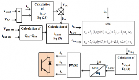
Figure 6. Voltage source converter control based on SMC controller
Sliding Mode controller (SMC) is robust method, it is a non-linear type control that has been introduced for the control of variable structure systems and is based on the concept of controller structure change with the state of the system in order to obtain a desired response. The sliding mode control is therefore all or nothing type.
Sliding Mode is based in three steps:
- Choice of sliding surfaces S(X).
- Definition of the conditions of existence and convergence of the sliding regime.
- Determination of the control law.
The sliding mode control law is expressed by [26]:
$U=u_{e q}+u_{n}$ (6)
where ueq is the calculated control and un is given by:
$u_{n}=-k^{*} \operatorname{sign}(S)$ (7)
S: slotine surface.
k: constant value
In this paper, we chose slotine surface [26-28], and apply it in equation 8and 9 to calculate ucd,q:
The first system:
$L_{f} \frac{d i_{d}}{d t}=u_{c d}-R_{f} i_{d}+L_{f} w i_{q}-e_{d}$ (8)
The second system:
$L_{f} \frac{d i_{q}}{d t}=u_{c q}-R_{f} i_{q}-L_{f} w i_{q}-e_{q}$ (9)
The first surface is used to calculate ucd:
$S_{1}=\left(\frac{d}{d t}+\lambda\right)^{n-1} e_{1}$ (10)
For n=1, the surface can be written by:
$S_{1}=e_{1}=i_{d r e f}-i_{d}$ (11)
The derivate surface is expressed [26]:
$\dot{S}_{1}=\dot{i_{d r e f}}-\dot{i_{d}}=u_{n 1}=-k_{1} \operatorname{sign}\left(S_{1}\right)$ (12)
By replacing equation (8) in equation (12):
${i_\dot{\text {dref}}}-\frac{1}{L_{f}}\left(u_{c d}-R_{f} i_{d}+L_{f} w i_{q}-e_{d}\right)=-k_{1} \operatorname{sign}\left(S_{1}\right)$ (13)
$u_{c d}=L_{f}\left(\dot{i_{\text {dref}}}+R_{f} i_{d} / L_{f}-L_{f} w i_{q} / L_{f}+e_{d} / L_{f}\right)+L_{f} k_{1} \operatorname{sign}\left(S_{1}\right)$ (14)
The voltage control is:
$u_{c d}=L_{f}\left(k_{1} \operatorname{sign}\left(S_{1}\right)+\dot{i_{\text {dref}}}\right)+R_{f} i_{d}-L_{f} w i_{q}+e_{d}$ (15)
The second surface is used to calculate ucq:
$S_{2}=\left(\frac{d}{d t}+\lambda\right)^{n-1} e_{2}$ (16)
The order of the system is n=1, in that case:
$S_{2}=e_{2}=i_{\text {qref }}-i_{q}$ (17)
The derivate surface is:
$\dot{S_{2}}=\dot{i_{\text {qref}}}-\dot{i_{q}}=u_{n 2}=-k_{2} \operatorname{sign}\left(S_{2}\right)$ (18)
By replacing equation (9) in equation (18):
$\dot{i_{\text {qref}}}-\frac{1}{L_{f}}\left(u_{c q}-R_{f} i_{q}-L_{f} w i_{d}-e_{q}\right)=-k_{2} \operatorname{sign}\left(\mathrm{S}_{2}\right)$ (19)
$u_{c q}=L_{f}\left(\dot{i_{\text {qref }}}+R_{f} i_{q} / L_{f}+L_{f} w i_{q} / L_{f}+e_{d} / L_{f}\right)+L_{f} k_{2} \operatorname{sign}\left(S_{2}\right)$ (20)
The voltage control is:
$u_{c q}=L_{f}\left(k_{2} \operatorname{sign}\left(S_{2}\right)+\dot{i_{\text {qref}}}\right)+R_{f} i_{q}+L_{f} w i_{q}+e_{d}$ (21)
The reaching condition must be verified:
$\left\{\begin{array}{l}S_{1} \dot{S}_{1}=S_{1}\left(-L_{f} k_{1} \operatorname{sign}\left(S_{1}\right)\right)<0 \\ S_{2} \dot{{S_{2}}}=S_{2}\left(-L_{f} k_{2} \operatorname{sign}\left(S_{2}\right)\right)<0\end{array}\right.$ (22)
Therefore, the ranges of switching gains are given as follows:K1, K2>0.
Lf and Rfrepresent the coupling inductance and resistance of a phase of the filter between the VSC and the grid.
n: system order.
λ, k1, k2: positive constants values
2.3 Voltage regulators
The active reference power Pref from equation (5) to be injected into thegrid is calculated as follows:
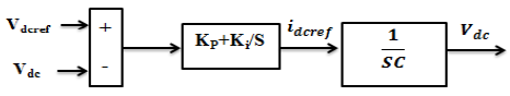
$i_{\text {dcref}}=V_{d c}\left(I_{\text {inj}}-P I\left(V_{\text {dcref}}-V_{d c}\right)\right)$ (23)
$P_{\text {ref}}=V_{d c} i_{\text {dcref}}$ (24)
Vdcref and Vdc are the reference voltage of the bus continue.
Iinj is inected current to the bus continue.
Figure 7. Bus continue voltage regulation loop using PI regulator
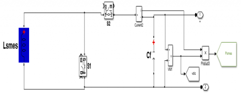
In order to regulate the power demand of the powersystem,the magnitude and the voltage polarity across the coil must be controlled using DC-DC chopper, the DC-DC chopper allows to control the voltage across the capacitor and supply the required currentin the superconducting coil. It has two legs in parallel to distribute the SMES current.
In this paper, novel Dc-Dc chopper has been proposed and investigated as it’s shown in Fig 8, the SMES is charged from PV system and connected the Grid with two modes, the first mode is discharge mode, and in this mode the SMES will be controlled by PID classical regulator to regulate the error as is expressed in equation (25), the second mode is standby, in this mode the SMES is disconnected to the Grid by short circuit.
Figure 8. SMES system
$\left\{\begin{array}{l}P_{c h}=P_{S M E S}+P_{r} \\ e=\left(P_{c h}-P_{r}\right)-P_{S M E S}\end{array}\right.$ (25)
With
$P_{\text {SMES}}=V_{d c} * I_{\text {inj}}$ (26)
Pr, Pch are the grid and load power respectively.
RESULTIn order to study the efficiency of proposed method control strategy, power system with PV system and SMES has been used,in which the following simulation have been carried out and analyzed:
1.GPV connected to Grid with fix and variable load.
2.SMES connected to Grid with fix load.
3.SMES connected to Grid with variable load.
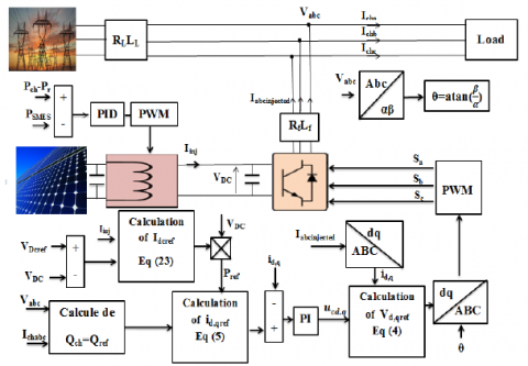
The global bloc diagram is shown in fig 9, table 1 shows the system parameters.
Figure 9. Bloc diagram of proposed Grid-PV-SMES connected
Table 1: system parameters
|
Parameters |
|
Values |
|
DC-DC Boost |
Cpv |
4e-4F |
|
L |
0.02H |
|
|
Bus continue |
Cdc |
1.89e-04F |
|
Sliding mode ucd |
K1 |
0.2 |
|
Sliding mode ucq |
K2 |
13.5 |
|
|
Lf |
0.0071H |
|
VSC output filter |
Rf |
0.02 ohm |
|
|
V |
220v |
|
Grid and grid filter |
R |
0.003 ohm |
|
|
L |
2.6e-6H |
|
|
R |
5.6 ohm |
|
The first load |
L |
26.6e-3 H |
|
|
R |
8.4 ohm |
|
The second load |
L |
40e-3 H |
|
SMES |
L |
1.8H |
The MPPT used is PID controller which controls the error between GPV voltage output and the reference voltage which is calculated by the equation (27).
$V_{\text {ref }}=S_{e}\left(\frac{N_{s} A K T}{q} \log \left(\frac{I_{p h}-I_{\text {ref}}+I_{0}}{I_{0}}\right)\right)$ (27)
With Se is the number of series solar panel.
Where: Iref=0.909 Iph.
I0 is the cell reverse saturation current.
Ns are the number of cells connected in series.
q = 1.6 × 10⁻¹⁹[C] is the electron charge.
K = 1.3805 × 10⁻²³[J/K] is the Boltzmann constant.
A is the ideality factor of the p-n junction.
T[K] is the cell temperature.
4.1 GPV-Grid (Fixed and variable load)
Generator photovoltaic (GPV-3000W) is connected to the grid, a comparative study between PI and sliding mode regulators is presented where two scenarios have been considered fixed and variable load: inthe first case : four irradiation steps have been applied 1000, 600, 800 and 1000 w/m2 with constant load (fig 10). In the second case a variable load has been employed to confirm the efficiency of proposed control methods .
From fig 10 and 11: both regulators guarantee good performances of injected power into grid, however PI regulator shows a considered overshoot and response time compared to sliding mode controller. In addition,it’s clear that GPV output poweroperates perfectly in which the MPP has been tracked for different irrradiation.
Figure 10. The load, grid and GPV output power under variable irradiation using sliding Mode and PI controller
Figure 11. The load, grid and GPV output power with variable load using sliding Mode and PI controller
The GPV output power is perfectly calculated by the PID regulator under all the irradiation changes, with no oscillation or overshoot and fast response time.
4.2 SMES-Grid with fixed load
In most areas, the average irradiation can almost reach 7 hours/day and energy demand is nearly unplanned, so the use of SMES can be more suitable to overcome the previous dilemmas, where the exceed energy can be stored, then it injected in power system during peak power demand or during specify time, based on the previous remarks, we present in this section power system containing a SMES. The SMES connect to the grid with two modes in the same simulation (discharged and standby), the SMES is in standby mode from 0.37 to 0.65 second, and is connected to the grid in the rest time.
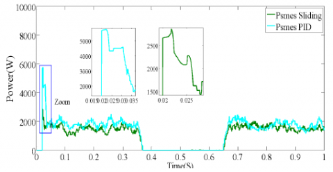
Figure 12. The load, grid and exchanged power using sliding Mode and PI controller
Figure 13. Zoom (A): The load, grid and exchanged power using sliding Mode and PI controller
Figure 14. Zoom (B): The load, grid and exchanged power with comparative between sliding Mode and PI controller
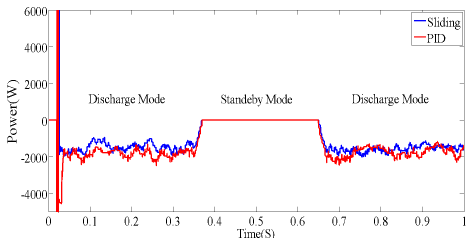
Figure 15. SMES power in standby and discharge mode with comparative between sliding Mode and PI controller
Figure 16. SMES voltage in standby and discharge mode with comparative between sliding Mode and PI controller
Figure 17. SMES energy in standby and discharge mode with comparative between sliding Mode and PI controller
From Figs 12, 13 and 14, Injected SMES energy in power system has been controlled perfectly by both developed control strategies sliding mode and field oriented control based on PI controller, where the equality is always ensured: Pch= Pr+Psmes. We can observe when the SMES injectes the power in the grid, the power grid decrease according the equality (equation (25) and when the SMES is disconneted (Psmes=0) all load power is generated by the grid.Obtained results demostrates the efficiency of both methods sliding mode and PI controller, however the sliding mode shows better performances in term ofresponse time and overshot, as shown in fig 13 and 14. In standby mode the SMES is short circuit, in this mode the voltage and the power are null as is shown in figs 15 and 16, also the same note obtained in figs 15 and 16 for the performance of sliding mode and PI controller. Fig 17, shows how does the power SMES changeduring both modes discharging and standby mode.
4.3 SMES-Grid with variable load
In this simulation part, the load changes from the first to the second load, the SMES is injected to the grid with no standby mode and with same condition in (SMES-Grid with fixed load).
Figure 18. The load, grid and exchanged power with load change and comparative between sliding Mode and PI controller
Fig 18 shows the power grid, power SMES and load in variable loads scenario, it clear that both control strategies sliding mode and PI regulator provide a high performances with small superiority of sliding mode in term of low oscillations.
In this paper, power grids containing photovoltaic systemand storage system based on Superconducting Magnetic Energy Storage (SMES) has been proposed and analyzed for different possible scenarios and loads. Modeling and operating principle of SMES and Power-PV-SMES have been explained in details. Injected SMES energy in power system has been controlled perfectly by both developed control strategies sliding mode and field oriented control based on PI controller, where sliding mode ensures better performance compared to field oriented control. Beside the efficiency of proposed control methods, obtained results demonstrate the great benefit of use of combined renewable energy-SMES to confront the future demand with the exiting power production capacity and maintain the power system operation under hard conditions. Hence, renewable energy-SMES can be widely used for quality power improvement.
[1] Wu, D., Chau, K. T., Liu, C., Gao, S., & Li, F. (2011). Transient stability analysis of SMES for smart grid with vehicle-to-grid operation. IEEE Transactions on Applied Superconductivity, 22(3), 5701105-5701105.
[2] Yunus, A. S., Abu-Siada, A., & Masoum, M. A. S. (2011, November). Application of SMES unit to improve the high-voltage-ride-through capability of DFIG-grid connected during voltage swell. In 2011 IEEE PES Innovative Smart Grid Technologies (pp. 1-6). IEEE.
[3] Jung, H. Y., Park, D. J., Seo, H. R., Park, M., & Yu, I. K. (2009, March). Power quality enhancement of grid- connected wind power generation system by SMES. In 2009 IEEE/PES Power Systems Conference and Exposition (pp. 1-6). IEEE.
[4] Jung, H. Y., Kim, A. R., Kim, J. H., Park, M., Yu, I. K., Kim, S. H., ... & Tamura, J. (2009). A study on the operating characteristics of SMES for the dispersed power generation system. IEEE Transactions on Applied Superconductivity, 19(3), 2028-2031.
[5] Kim, S. T., & Park, J. W. (2014). Energy Management Strategy and Adaptive Control for SMES in Power System with a Photovoltaic Farm. J ElectrEngTechnol, 9(4), 1182-1187.
[6] Badr, M. A., Atallah, A. M., & Bayoumi, M. A. (2016). Performance analysis of SMES integrated with offshore wind farms to power systems through MT- HVDC. Indonesian Journal Of Electrical Engineering And Computer Science, 4(1), 1.
[7] Sahoo, A. K., Mohanty, N., & Anupriya, M. (2015). Modeling and Simulation of Superconducting Magnetic Energy Storage Systems. International Journal of Power Electronics and Drive Systems (IJPEDS), 6(3), 524.
[8] Aly, M. M., Mohamed, E. A., Salama, H. S., Said, S. M., Abdel-Akher, M., & Qudaih, Y. (2016). A developed voltage control strategy for unbalanced distribution system during wind speed gusts using SMES. Energy Procedia, 100(1), 271-279.
[9] Jiang, Q., & Conlon, M. F. (1996). The power regulation of a PWM type superconducting magnetic energy storage unit. IEEE transactions on energy conversion, 11(1), 168-174.
[10] Kustom, R. L., Skiles, J. J., Wang, J., Klontz, K., Ise, T., Ko, K., & Vong, F. (1991). Research on power conditioning systems for superconductive magnetic energy storage (SMES). IEEE transactions on magnetics, 27(2), 2320-2323.
[11] Gil-González, W. J., Garcés, A., & Escobar, A. (2017). A generalized model and control for supermagnetic and supercapacitor energy storage. Ingeniería y Ciencia, 13(26), 147-171.
[12] Salbert, H., Krischel, D., Hobl, A., Schillo, M., Blacha, N., Tromm, A., & Roesgen, W. (2000). 2 MJ SMES for an uninterruptible power supply. IEEE transactions on applied superconductivity, 10(1), 777-779.
[13] Jun, L., Cheng, K. W. E., Xu, D., & Sutanto, D. (2003, June). Multi-modular current-source based hybrid converter for SMES. In IEEE 34th Annual Conference on Power Electronics Specialist, 2003. PESC'03. (Vol. 1, pp. 94-98). IEEE.
[14] Liu, F., Mei, S., Xia, D., Ma, Y., Jiang, X., & Lu, Q. (2004). Experimental evaluation of nonlinear robust control for SMES to improve the transient stability of power systems. IEEE Transactions on Energy Conversion, 19(4), 774-782.
[15] Nomura, S., Tsutsui, H., Tsuji-Iio, S., & Shimada, R. (2006). Flexible power interconnection with SMES. IEEE transactions on applied superconductivity, 16(2), 616-619.
[16] Feak, S. D. (1997). Superconducting magnetic energy storage (SMES) utility application studies. IEEE transactions on power systems, 12(3), 1094-1102.
[17] Lee, Y. S., & Wu, C. J. (1991, September). Application of superconducting magnetic energy storage unit on damping of turbogenerator subsynchronous oscillation. In IEE Proceedings C (Generation, Transmission and Distribution) (Vol. 138, No. 5, pp. 419-426). IET Digital Library.
[18] Seo, H. R., Kim, A. R., Park, M., & Yu, I. K. (2011). Power quality enhancement of renewable energy source power network using SMES system. Physica C: Superconductivity and its Applications, 471(21-22), 1409-1412.
[19] Luo, X., Wang, J., Dooner, M., & Clarke, J. (2015). Overview of current development in electrical energy storage technologies and the application potential in power system operation. Applied energy, 137, 511-536.
[20] Zhou, X., Chen, X. Y., & Jin, J. X. (2011, December). Development of SMES technology and its applications in power grid. In 2011 International Conference on Applied Superconductivity and Electromagnetic Devices (pp. 260-269). IEEE.
[21] Shi, J., Tang, Y. J., Ren, L., Li, J. D., & Chen, S. J. (2008). Application of SMES in wind farm to improve voltage stability. Physica C: Superconductivity, 468(15- 20), 2100-2103.
[22] Kim, S. T., Kang, B. K., Bae, S. H., & Park, J. W. (2012). Application of SMES and grid code compliance to wind/photovoltaic generation system. IEEE transactions on applied superconductivity, 23(3), 5000804-5000804.
[23] Harada, N., Toyoda, K., Minato, T., Ichihara, T., Kishida, T., Koike, T., ... & Murakami, Y. (1997). Development of a 400 kJ Nb3Sn superconducting magnet for an SMES system. Electrical engineering in Japan, 121(3), 44-52.
[24] Buckles, W., & Hassenzahl, W. V. (2000). Superconducting magnetic energy storage. IEEE Power Engineering Review, 20(5), 16-20.
[25] Aware, M. V., & Sutanto, D. (2003). Improved controller for power conditioner using high-temperature superconducting magnetic energy storage (HTS- SMES). IEEE transactions on applied superconductivity, 13(1), 38-47.
[26] Slotine, J. J. E., & Li, W. (1991). Applied nonlinear control (Vol. 199, No. 1). Englewood Cliffs, NJ: Prentice hall.
[27] Kechich, A., & Mazari, B. (2008). La commande par mode glissant: Application à la machine synchrone à aimants permanents (approche linéaire). Afrique Science, 4(1), 21-37.
[28] Assam, B., Messalti, S., & Hrrag, A. (2019). New improved hybrid mppt based on backstepping-sliding mode for pv system. Journal Européen des Systèmes Automatisés, 52(3), 317-323.