V. Velmurugan* | V. Paramasivam | S. Thanikaiarasan | T. PVaikundraj
OPEN ACCESS
Diesel Engine vibration in the passenger vehicles is one of the challenging tasks to obtain drivability, stability and comfort of the occupants especially the diesel engine cars that have higher compression ratio leads to more amount of vibration generation from the engine which is subsequently transferred to the steering wheel and seat. Considering the vibration isolation and to decrease the low fre- quency vibration during the idle condition of the engine, the engine mount plays a major role in absorbing the vibration since the engine is mounted over it and the characteristics of the mount like its damping property and stiffness value are to be evaluated.. Since the engine mounting used normally in the diesel engine vibrations are elastomers like natural rubber which is having good mechanical property in attaining the better vibration isolation. Here in this paper we are going to do the experimental investigation in the two cylinder four stroke diesel engine with the natural rubber mount and fluorocarbon blended rubber mount and hydraulic mount by applying the various excita- tion that is transferred from the engine to the structure, seat and steering wheel and results were compared for the optimization of engine mount material that has recommended stiffness and dynamic coefficient during idle condition.
Diesel engine; rubber mount; fluorocarbon; vibration; noise
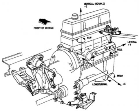
The internal combustion (IC) engine is the concentrated mass in vehicle and if not properly designed it will cause vibrations and transfer to the supporting structures ride comfort, driving stability and drivability are important factors for the performance of a vehi- cle and are affected by the engine vibrations. Because of the envi- ronmental considerations, as well as changes in consumer prefer- ences regarding vibration induced must be reduced. Vibration behavior of an IC engine depends on unbalanced reciprocating and rotating parts, cyclic variation in gas pressure, shaking forces due to the reciprocating parts and structural characteristics of the mounts. Engine vibrations are caused due to the reciprocating and rotating masses of the engine as shown in Fig.1. The variations of inertial forces are due to the combustion and the compression dif- ferences of the piston cylinder arrangement during their operation. The engine inertial forces leads to the unbalanced forces of the engine and they are quiet varying with respect to speed, fuel sup- ply and combustion characteristics of the fuel. To predict the vi- bration output of an engine and to minimize the possible durability and consumer perceived quality problems associated with engine vibration, a robust and accurate design and simulation model is needed. To reduce the engine vibration proper mounting must be provided as dampers at the interface of the engine and chassis.[1]
Engine vibrations can be classified as internal and external vibrations. The internal vibrations are referred to as the vibrations of internal components of the engine, induced by the inertial force of moving parts and the variable pressure of combustion. These vi- brations usually must be suppressed to avoid engine malfunctions and damage/fracture and noise of parts. The frequently encoun- tered vibrations are torsion and bending vibrations of the crank- shaft, and vibration of the valves-camshaft system. The severe torsion and bending vibrations of the crankshaft could lead to frac- ture of the shaft and/or damage to the bearings. Most of the internal vibrations result in noise, and are unlikely to cause dangerous stress of parts. The external vibrations are referred to as the vibrations of the entire engine system as a block, which is usually integrated with the transmission case. The external vibrations are due to un- balanced moment, inertial moment, or variable-output torsion torque.Diesel engines emit higher radiated noise levels than gaso- line engines of the same size. Noise emitted from the diesel’s injec- tion system and combustion process results in generally inferior sound quality compared to gasoline engines [2]. Higher engine mount vibration levels and crankshaft torsions are more prevalent in modern diesel engines than gasoline engines, because of the diesel engine’s high cylinder peak pressures and pressure rise rates. As a result, when diesel engines are integrated into passenger vehi- cles designed primarily for gasoline engine applications, significant NVH optimization is required to make the diesel vehicles competi- tive. [3] NVH stand for Noise, vibration and harshness, Noise is unwanted sound in the whole audible range of 20-20kHz, vibration in vehicle; however is usually a topic of vehicle tactile response of up to 100Hz. Among the three, harshness is the only one that is not well recognized by other industries. Harshness is a term that de- scribe human’s subjective feeling on an event. Harshness is created when a person’s subjective feeling is not in agreement with his/her anticipation. For an example, when a customer sees a smooth road surface on road, he/she would have an anticipated low level of noise and vibration level when he or she drives the vehicle on that road surface. But if the vehicle has more than anticipated level of noise and vibration, harshness feeling is created in the mind of the driver. In vehicle NVH we use sound pressure level (dB, dBA, sometimes dB(B) or dB(C)) when describing an engineering noise phenomena, such as engine noise, road noise, sound transmission etc [4]; We use psychoacoustics terms such as loudness, sharpness, roughness, articulation index, etc when we describe items that re- late to customer perception of a noise. For the vehicle’s tactile vi- bration, due to the fact human’s perception is flat in frequency with velocity, velocity is often used as the primary metric for vibration when dealing with items that relates to customer perception and use acceleration for general engineering items. Vehicle NVH [5] is usually studied into two categories in air borne and structure borne NVH. It is usually believed that 300-500Hz is the cut off frequency, below which structure born NVH is dominant and above which air born NVH is more dominant. Both experiments and CAE analy- sis have proven that being a good frequency separating point for the structure and air borne NVH [6]. The engine mounts should have characteristics of high stiffness and high damping in the low frequency rangeand of low stiffness and low damping in the high- frequency range. Hydraulic mountsdo not perfectly satisfy such requirements [7]. Although hydraulic mounts greatly increase damping at low frequencies, they also degrade isolation perfor- mance at higher frequencies. Hydraulic mounts are not cost effec- tive; they had complexity in design and low reliability [8]. Though various types of hydraulic mounts have been developed for the vehicle mount systems, it is still reported that the rubber mounts and bolted joints show significant importance in ride comfort and reduced noise levels. Bolted joints can be designed for the neces- sary elastic stiffness rate characteristics in all directions for proper vibration isolation. They are compact, cost-effective, and largely maintenance free [9].
Figure 1. Four stroke Diesel Engine power train
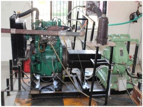
Figure 2. Two Cylinder 4 stroke DI Engine Experimental setup -
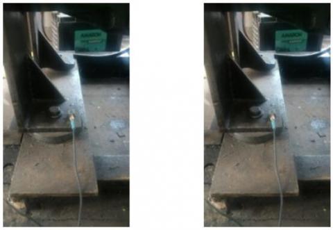
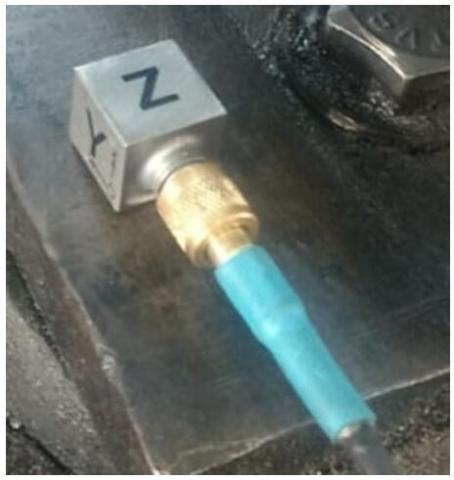
Figure 3. Tri-axial Sensor on left and right bottom of the engine with NR mount
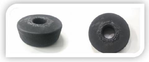
Figure 4. 40% Fluorocarbon Natural Rubber Model
Results of the paper enable the designer an easy way to adjust the stiffness parameter by tightening of bolts to the supports,which helps in reducing the overall vibration and noise.
Elastomeric mounts can be designed for the necessary elastic stiffness rate characteristics in all directions for proper vibration isolation. They are compact, cost-effective, and maintenance free. Bonded elastomeric mounts are known to provide more consistent performance and longer life. The elastomeric mount can be repre- sented by the familiar Voigt model which consists of a springand a viscous damper. The dynamic stiffness of an elastomeric mount will be greater at higher frequencies than its stiffness at lower fre- quencies due to damping [10]. All hydraulic mounts reported in the literatureare conceptually similar but differ in detailed structural design. Three typical hydraulic mounts are: hydraulic mount with simple orifice, hydraulic mount with inertia track and hydraulic mount with inertia track and de-coupler[11], usually the dynamic stiffness of hydraulic mount with simple orifice or inertia track is greater than that of a comparable elastomeric mount. Although these kinds ofhydraulic mounts greatly increase damping at low frequencies [12], they also degrade isolation performance at higher frequencies.An engine mount with asemi-active control mechanism is called a semi-active engine mount. Semi-active control can change the dynamic response of the system through controlling system parameters. The controlled parameters for a semi-active engine mount system can be elastic stiffness and damping. Electro- Rheological fluids ER fluidhas drawn much attention in the semi- active control of engine mounts because of their rapid change in viscosity properties when an electric field is applied.In active vibra- tion control, a counteracting dynamic force is created by one or more actuators in order to suppress the transmission of the system disturbance force [13]. In other words, an active energy source should be continuously supplied to counteract the continuously generated target energy source. A typical active mount consists of a passive mountelastomeric or hydraulic, force generating actuator, a structuralVibration sensor and an electronic controller [14].
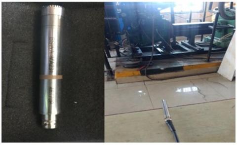
Figure 5. Tri axial accelerometer
Here the Natural Rubber (NR) mount is shown in Fig.3 and the 40% Blended Fluorocarbon NR mount is as shown in Fig.4.
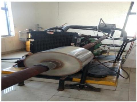
The Physical and Mechanical properties of the elastomers say the NR mount and the FKM or the NR mount blended with the fluoro- carbon are tabulated as shown in the table-2, Which discusses the hardness, tensile stress, compression test and tear strength also shows the glass transition temperature which shows the blended fluorocarbon NR mount with better properties which can be used as the Engine isolators. Catalyst substrates covered with the dynamic catalyst wash coat are bundled in steel housing to shape exhaust systems. The major design consideration of catalytic converter is mechanical durability, heat losses, exhaust flow distribution and pressure drop. The two key aspects of the overall durability of an emission control system are emission performance and mechanical durability. The emission durability relies upon the nature of the catalyst coating and on the working conditions, for example, tem- perature or levels of impetus harms in the exhaust gas. The catalyt- ic converter design needs to give the required mechanical system durability. In this project we are using three way catalytic converter as shown in Fig.5, The three-way oxidation-reduction devices are utilized as a part of vehicle emission control system in many parts of the world including the U.S and Canada. The strict vehicle emis- sion regulation has ordered to utilize the three-way catalytic con- verters on fuel powered vehicles. These converters have come to be perceived as a standout amongst the most essential creations ever of automobiles. These perform three tasks, in particular, reduction of nitrogen oxides to nitrogen and oxygen, oxidation of carbon monoxide to carbon dioxide, and oxidation of unburnt hydrocar- bons to carbon dioxide and water.[9].
Figure 6. Transducer
The Problem that is identified in this project is to reduce the noise and vibration in the diesel engine passenger vehicle which contributes the low frequency noise due to the vibration occurring in the engine and its structures during idle condition which is an- noying and create fatigue to the occupants and the driver. As it is identified from the literature survey from various journals that the engine mount is one of the components which connects the chassis, car body and engine that can act as isolators and can considerable reduce the vibration.
2.1. Accelerometer
The acceleration forces is measured using electromechanical device is known as accelerometer which is shown in Fig.6. Such forces might be static, similar to the continuous force of gravity or, just like the case with numerous mobile devices, dynamic to detect development or vibrations. An accelerator resembles a straightfor- ward circuit for some bigger electronic device. In spite of its small appearance, the accelerometer comprises of a wide range of parts and works from various perspectives, two of which are the piezoe- lectric effect and the capacitancesensor. The piezoelectric impact is the most widely recognized type of accelerome- ter and microscopic crystal structures that end up stressed because of accelerative forces. These crystals make a voltage from the pres- sure or stress, and the accelerometer translates the voltage to decide velocity and orientation. This Tri-axial accelerometer sensor is used to measure vibration.
2.2. Transducer
The device that used to change the physical attributes of non- electrical signal into electrical signal is known as transducer as shown in Fig.7, Here the electrical signal is easily measurable. The energy conversion process in transducer is called as transduction. There are two steps to complete transduction. First step is sensing the signal and second step strengthening it for upcoming pro- cessing. This transducer sensor is used to measure noise.
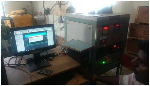
Figure 7. Dewesoft system shows the frequency spectrum analysis output
Figure 8. Catalytic converter attached to Engine
2.3. Dewesoft
DEWESoft is measurement software which is shown in Fig.8 can obtain information from entirely different estimation hardware and empowers the client to do preparing, storage and investigation es- sentially. The fundamental thought of Dewesoft is to have two methods of task: Acquisition and Analysis. The primary contrast is that Acquisition part works with a genuine hardware while Analy- sis works with put away document. Be that as it may, same math preparing and representation can be connected either during meas- urement or likewise on stored files. In this manner the parts of the manual depicting the Measurement are valid also for investiga- tion.DEWEsoft is the one of the leading software used for vibration and noise analysis.
Table 1. Engine Specification
|
Engine |
Diesel |
|
Capacity |
21KW |
|
Configuration |
Vertical Inline engine |
|
Stroke |
127 mm |
|
No. of Cylinders |
2 |
|
Displacement |
1670 cc |
|
Compression ratio |
18.5:1 |
|
Cycle |
4 Stroke |
Table 2. NR and NR blended Material Property
|
Property ASTM designation |
Natural Rubber Mount |
Fluorocarbon blended NR Mount |
|
Density (kg/m³) |
0.93 *10³ |
0.95*10³ |
|
Tensile strength (Mpa) |
20 |
30 |
|
Elongation (%) |
800 |
900 |
|
Glass transition temperature (ºC) |
-70 |
-23 |
|
Maximum work temperature (ºC) |
80 |
90 |
|
Electric resistivity (Ohm*m) |
107-109 |
|
|
Dielectric constant |
2.7 |
2.8 |
|
Durometer range |
30-90 |
60-90 |
|
Compression set |
Good |
Good |
|
Tear resistance |
Good |
Good |
|
Resilence |
High |
High |
|
Weather resistance |
Poor |
good |
|
Oil resistance |
Average |
good |
The method that is followed here the experimental test rig of a two cylinder diesel engine shown in table.1 is used to test the exist- ing Natural rubber mount, and a modified Natural rubber mount with fluorocarbon blended and a hydraulic mount is tested in the four cylinder car.
The vibrations caused in the test rig and the engine were noted for the various parameters like road conditions, speed and load variations and the behavior of the mounts specified above are com- pared. In the test rig of the two cylinder four stroke diesel engine is fixed with the sensors are the engine block head and the reading are obtained as output by connecting to the data acquisition system that which stores the vibration occurring during the Natural rubber mount is used and subsequently the vibration are recorded and sent to the dewesoft for the analysis and the datas have been recorded the engine speed of 1100 rpm is constant and the load are varied from 25%, 50%, 75% and 100% where the vibrations are recorded in terms of acceleration(g). The same procedure is repeated on the right mount for the same speed, torque is noted and acceleration is tabulated.Again the manufactured blended fluorocarbon NR is used as the left mount and the procedure is repeated for the 25%, 50%, 75% and 100% where the vibrations are recorded in terms of accel- eration(g).Again the same is continued for the hydraulic mount but it is been done in the four stroke four cylinder diesel engine car directly for recording the performance at the specified say 20 kmph and the acceleration is measured.
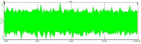
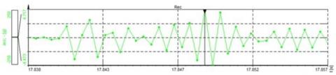
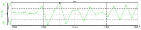
The vibration is measured in the test rig by mounting the Natural rubber mount which is mounted on the left bottom of the engine shows the acceleration values in terms of g as shown in table-3, and the acceleration values measured by mounting the natural rubber mount on the right bottom of the engine as shown in table 4 has a minor variation, similar the table- 5 shows the Fluorocarbon blend- ed NR mount which is located near the left bottom of the engine and table-6, shows the mount on the right bottom. It is observed that the acceleration or the amplitude values of the blended fluoro- carbon NR rubber mount has lesser value of the acceleration com- pared to the original NR mount which shows that the fluorocarbon mount has better vibration absorption capacity.In addition to the it is also recommended for the attachment of the catalytic converter is attached to the engine for improving the emission control which also influences the vibration increase in the diesel engine vibration and noise and hence the numerical values shows the vibration and noise in the engine with and without catalytic converter for the NR mountshown in table-7 and for Fluorocarbon blended NR mount is shown in table-8. From the values observed that the vibration and noise values are reduced for the fluorocarbon blended NR mount when compared to the normal NR mount. The Fig.9 and Fig.10 shows graph of the amplitude values for the vibration due to the NR mount performance without and with the catalytic converter and the Fig.11 and Fig 12 shows the amplitude values of vibration due to the fluorocarbon blended NR mount without and with the catalytic converter. In addition to this the Vibration and noise vari- ation for the respective catalytic converter of the natural rubber and fluorocarbon for a 50% load value as a example and finally the comparison chart of the vibration and noise for the respective speed of 1100 rpm and for the variation of the different mount with and without the catalytic converter are show in the Fig.13 and Fig.14.
Table 3. Natural rubber mounts readings on the left bottom of the engine
|
Speed (rpm) |
LOAD(%) |
TORQUE(N.m) |
ACCELERATION |
|
1100 |
FULL LOAD |
92.3 |
8.3 g |
|
|
75% |
69.2 |
11.4g |
|
|
50% |
46.1 |
6.3 g |
|
|
25% |
23.1 |
7.1 g |
Figure 9. Natural rubber mounting without catalytic converter-at 50% load
Figure 10. Natural rubber mounting with catalytic converter-50% Load
Table 4. Natural Rubber mounts readings on the right bottom
|
RPM |
LOAD IN (%) |
TORQUE |
ACCELERATION |
|
1100 |
FULL LOAD |
92.3 |
4.6 g |
|
|
75% |
69.2 |
5.8 g |
|
|
50% |
46.1 |
5.5 g |
|
|
25% |
23.1 |
5.3 g |
Table 5. Fluorocarbon blended(40%) NR mounts reading on the left bottom
|
Speed (rpm) |
LOAD (%) |
TORQUE(N.m) |
ACCELERATION |
|
1100 |
FULL LOAD |
92.3 |
6.0 g |
|
|
75% |
69.2 |
5. 5 g |
|
|
50% |
46.1 |
5.9 g |
|
|
25% |
23.1 |
5.8 g |
Table 6. Fluorocarbon blended(40%) NR mounts reading on the Right bottom
|
Speed (rpm) |
LOAD (%) |
TORQUE(N.m) |
ACCELERATION |
|
1100 |
FULL LOAD |
92.3 |
4.7g |
|
|
75% |
69.2 |
5.8g |
|
|
50% |
46.1 |
5.5g |
|
|
25% |
23.1 |
9g |
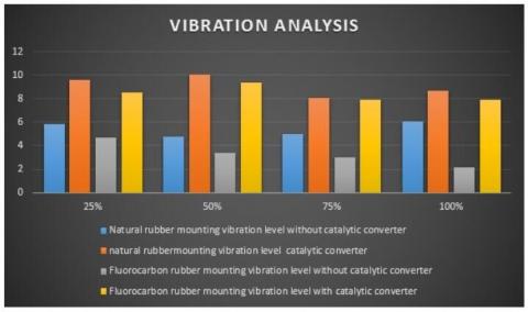
Table 7. Comparisonof Vibration analysis of NR and Fluorocar- bon NR mount
|
s.no |
Speed (RPM) |
Load % |
Natural rubber mounting vibration |
FIuorocarbon rubber mounting vibration |
||
|
Without catalytic converter |
With catalytic converter |
Without catalytic converter |
With catalytic converter |
|||
|
1. |
1100 |
25% |
5.809m/s2 |
9.602 m/s2 |
4.717m/s2 |
8.542m/s2 |
|
2. |
1100 |
50% |
4.77m/s2 |
m/s2 |
3.398m/s2 |
9.337m/s2 |
|
3. |
1100 |
75% |
5.025m/s2 |
m/s2 |
2.99m/s2 |
7.944m/s2 |
|
4. |
1100 |
100% |
6.085m/s2 |
m/s2 |
2.119m/s2 |
7.938m/s2 |
Table 8. Comparison of Noise Values for NR mount and Fluoro- carbon NR Mount
|
s.no |
Speed (RPM) |
Load % |
Natural rubber mounting Noise level |
Fluorocarbon mounting Noise level |
||
|
Without catalytic converter |
With catalytic converter |
Without catalytic converter |
With catalytic converter |
|||
|
1. |
1100 |
25% |
91.38dB |
84.37dB |
84.38dB |
77.37dB |
|
2. |
1100 |
50% |
99.36dB |
95.67dB |
87.67dB |
86.67dB |
|
3. |
1100 |
75% |
99.37dB |
99.30dB |
93.36dB |
86.30dB |
|
4. |
1100 |
100% |
99.79dB |
99.12dB |
88.12dB |
96.41dB |
Figure 11. Fluorocarbon NR rubber mounting without catalytic converter-50% load
Figure 12. Fluorocarbon rubber mounting with catalytic converter-at 50% load
Figure 13. Vibration analysis of NR and Fluorocarbon NR mount
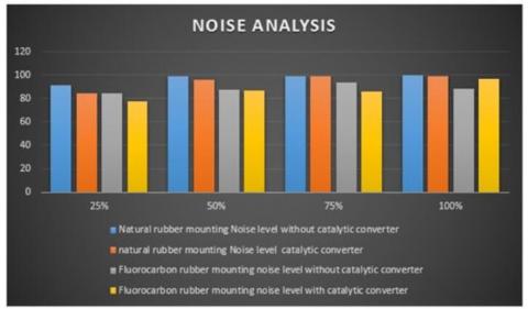
Figure 14. Noise analysis of NR and Fluorocarbon NR mount
From the above we can infer that vibrations and noise produced in the fluorocarbon mount is less the natural rubber mount. And we also investigated that catalytic converter is also responsible for the engine vibration and it affects theperformance of the vehicle.This paper covers the brief experimental investigation of Rubber and Fluorocarbon. Natural rubber consists of suitable polymers of the organic compound isoprene, with minor impurities of other organic compounds plus water. Fluorocarbon Blended NR mounts has more temperature and tear protection. The engine mount is being used to absorb and reduce the engine vibrations and noise. In the future still some other combination of rubber mount such as poly carbon or other types of polymers may be tested for better vibration and noise reduction purpose.
[1] T. Ramachandran, K.P. Padmanaban, International Journal of Engineering Sciences & Emerging Technologies, 3, 63 (2012).
[2] Yousef Alhouli et.al., Journal of Researches in Engineering: J General Engineering, 15, 6 (2015).
[3] Shubham Bharadwaj, Aman Gupta and Sunny Narayan, Int. J. Mech. Eng. Autom., 3, 249 (2016).
[4] Shaobo Young, Vehicle NVH development process and tech- nologies, The 21st International Congress on Sound and Vibra- tion 13-17 July, 2014, Beijing, China.
[5] Maria Antonietta Panza, Science direct, Energy Procedia, 82, 1017 (2015).
[6] N.S. Ahirrao, S.P. Bhosle, D.V. Nehete, Science direct, Pro- ceedia Manufacturing, 20, 434 (2018).
[7] Jiande Tianetal, “Dynamic characteristics of Semi-active Hy- draulic Engine Mount Based on Fluid-Structure Interaction FEA” MATEC web of conferences 31,06003(2015)
[8] S.S. Hosseini, J. Marzbanrad, Journal of Automotive Engineer- ing, 7, 4 (2017).
[9] Yadavalli Basavaraj Manjunatha.T.H, Journal of Engineering Science Invention, 2, 3 (2013).
[10] Yunhe yu, Saravanan M. et.al., Journal of Dynamic Systems, Measurement, and Contro, 186, 123 (2001).
[11] Y.H. Lee, J.S. Kim et.al., Prediction of dynamic stiffness on rubber components 2013 WILEY-VCH Verlag GmbH & Co. KGaA,Weinheim.
[12] Kadam et.al., International journal of latest trends in engineering and technology, 3,7(2016)_.
[13] Francis Augustine Joseph, Jason Cherian Issac, T J Paulson, Journal Of Scientific & Engineering Research, 4,(8), 2229 (2013).
[14] M Ajovalasit and J Giacomin, “Human subjective response to steering wheel vibration caused by diesel engine idle” Proc. IMechE. Vol. 219 Part D: J. Automobile Engineering (2005).