Moussa Charif* | Mourad Allad | Belkacem Moula
© 2026 The authors. This article is published by IIETA and is licensed under the CC BY 4.0 license (http://creativecommons.org/licenses/by/4.0/).
OPEN ACCESS
This work presents the design and practical implementation of a simplified Mamdani-type fuzzy proportional-integral (PI) controller with two inputs and two outputs (TITO) based on Larsen product inference, implemented on a Siemens programmable logic controller (PLC) platform. In oil, chemical, and manufacturing, precise level control in coupled batch processes is essential for maintaining product quality. This controller ensures the tank's liquid level remains at the desired setpoint by compensating for disturbances caused by coupling effects from other tanks in the system, as well as operational constraints by adjusting the inflow rate. The proposed fuzzy controller is designed with minimal complexity; each input variable is characterized by two fuzzy sets and five fuzzy sets for each output variable. The control strategy is defined by five linear IF-THEN rules, Larsen product inference, and the final crisp output value for each variable is computed using the Centre of Sums (CoS) defuzzification. The algorithm is implemented on a Siemens S7-300 industrial controller using structured control language (SCL) and ladder diagram (LAD), which will enable testing of the PI-fuzzy controller simplification approach and improvement of the dynamic performance of the system to be controlled. This paper has detailed the experimental outcomes of a simple fuzzy PI control strategy applied to the coupled PUL-2/EV device. The experimental results obtained with this simplified two-term fuzzy PI controller provide precise control for both setpoint tracking and disturbance rejection. Furthermore, the system provides monitoring capabilities and fault alerts on the developed human machine interface (HMI) screens using the designed algorithm.
two-term fuzzy controller, programmable logic controller, simplest fuzzy controller, two inputs and two outputs system, coupled systems control
The programmable logic controller (PLC) is a highly efficient and reliable computing unit designed for industrial automation and control. Its programming is standardized by ISO/IEC 61131 (2001). The advanced features of modern PLCs, such as floating-point calculations, data processing, and improved graphical interfaces, have enabled the development of new, more sophisticated control strategies in works [1, 2] and their integration into global intelligent management systems such as SCADA systems, as presented in works [3, 4]. Today's industrial PLCs are capable of handling numerous analog and digital inputs and outputs simultaneously. This allows them to execute multiple programs concurrently to perform complex control procedures. Modern PLC performance has spurred significant research into implementing more complex control algorithms in industrial settings [5, 6]. Notable research employing the LabJack U3 acquisition card and a MATLAB Guide platform is presented in this study [7]. In this study, a comparative study of three analytical design methods for fractional controllers (FOC) approaches are applied to the Level/Flow control unit PUL-2/EV. The objective of this paper is to examine the fundamental limitations associated with realizing isodamping in time-delay systems characterized by dominant lag. Experimental and analytical results demonstrate a degradation in iso-damping performance with increasing time delay, where the severity of this degradation is highly dependent on the chosen controller architecture and its tuning. An adaptive fuzzy proportional-integral (PI) controller was implemented to enhance the performance of the internal PID controller within a SIEMENS S7-300 PLC. This system was designed for precise speed control of an induction motor using a variable frequency drive [8]. Using the setpoint error e(t) and its variation Δe(t) as inputs, the fuzzy PI controller achieved a 50% reduction in response time compared to a conventional internal PI controller, as confirmed by experimental results. Several controllers are presented and used to control the attitude of six-degree-of-freedom quadrotor unmanned aerial vehicles (UAVs) in the study [9]. In this study, the proposed control strategies are evaluated individually, comprising a PID controller, a fuzzy logic PID controller, and an adaptive fuzzy logic PID controller. However, the system provided the best performance, particularly in terms of tracking error reduction and stability; the adaptive fuzzy logic PID controller outperforms the other methods. Standard PID controllers embedded in PLCs are not well-suited for complex, non-linear systems with significant time delays and coupled systems. For these challenging processes, fuzzy logic-based control strategies offer a more effective approach, providing better dynamic performance. As documented in the specialized literature, extensive research has been devoted to the mathematical modeling of simplified fuzzy controllers, which employ a reduced number of input and output signals. This modeling is typically realized through an approximation approach wherein the membership functions are defined as singletons over the interval [X, Y] of the controlled application [10].
Bosukonda and Kelothu [11] introduced new mathematical models for the simplest fuzzy PI/PD controllers by employing an equal universe of discourse for both scaled input variables. For the scaled output variable, this implementation employs L, Π, and Γ-type membership functions. The control signal is computed using Larsen product inference based on three linear fuzzy rules. A formula-based fuzzy PI controller is presented in this study [12]. Under sufficient conditions, this controller achieves closed-loop stability for bounded-input bounded-output (BIBO) systems, as proven using the small gain theorem. A Mamdani-type simplest fuzzy PI/PD controller for two inputs and two outputs (TITO) systems was analytically structured in this study [13] using the minimum inference method. A significant approach details the mathematical models and computational aspects of the simplest fuzzy controllers for TITO systems [14]. These models are particularly valuable as they demystify the controller's internal workings and facilitate direct implementation on industrial PLCs. Furthermore, a case study detailing the implementation of a fuzzy controller on a Siemens S7-300 PLC is provided in studies [15-18]. Our work implements a simple fuzzy PI controller on a Siemens 314-2DP PLC, equipped with an analog I/O module for signal interfacing. The controller is configured with two analog input channels and two analog output channels. Its fuzzy logic system employs triangular membership functions and an 81-rule base, where each rule is defined by a coordinate (p, q) from partitioned input planes. The remainder of this paper is organized as follows: A mathematical and structural description of the proposed TITO PI simplified fuzzy nonlinear controller is provided in Section 2. Section 3 introduces the experimental liquid level coupled apparatus and presents the mathematical modeling of its components. Section 4 describes the implementation process of the simplest nonlinear fuzzy two-term PI controller on a Siemens S7-300 PLC. Section 5 presents and discusses the simulation tests and experimental results, and the paper's conclusions are provided in Section 6.
Fuzzy logic, first introduced by Lotfi A. Zadeh in 1965, has since become a powerful methodology for the control of complex industrial processes. Its utility is particularly evident in systems characterized by nonlinearities or time-varying dynamics, where the development of accurate analytical models is challenging. The velocity form of the linear discrete-time TITO PI controller in speed form is defined by the following input-output relations, as given in works [13, 14]:
$\begin{gathered}\Delta u_1(q)=K_{P 1} \Delta e_1(q)+K_{I 1} \Delta e_1(q)+ \\ s_{21}\left[K_{P 2} \Delta e_2(q)+K_{I 2} \Delta e_2(q)\right] \\ u_1(q)=u_1(q-1)+\Delta u_1(q)\end{gathered}$ (1)
$\begin{aligned} \Delta u_2(q)=s_{12}\left[K_{P 1} \Delta e_1(q)+K_{I 1} e_1(q)\right]+ & + \\ K_{P 2} \Delta e_2(q)+K_{I 2} & e_1(q) u_2(q) \\ & =u_2(q-1)+\Delta u_2(q)\end{aligned}$ (2)
where,
$\begin{gathered}e_1(q)=r_1(q)-y_1(q) \\ \Delta e_1(q)=e_1(q)-e_1(q-1)\end{gathered}$ (3)
$\begin{gathered}e_2(q)=r_2(q)-y_2(q) \\ \Delta e_2(q)=e_2(q)-e_2(q-1)\end{gathered}$ (4)
where,
$K_{P_1}, K_{P_2}$: proportional factors
$K_{I_1}, K_{I_2}$: integral factors
r1, r2: reference commands
y1, y2: outputs of the TITO process
u1, u2: outputs of TITO controller
s12, s21: (- or +) signs depend on the loops interactions
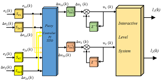
The overall structure of the TITO Fuzzy PI controller is illustrated in the block diagram of Figure 1.
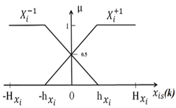
Figure 2. Scaled input membership function
The controller utilizes input scaling factors (Se1, SΔe1, Se2, SΔe2) and distinct output scaling factors for the PI ($S_{\Delta u_1}^{-1}, S_{\Delta u_2}^{-1}$) control actions. The scaled error inputs are denoted as e1s(k), Δe1s(k), e2s(k) and Δe2s(k). The resulting scaled control signals are Δu1s(k) and Δu2s(k) from the PI controller. The final level outputs of the process are l1(k) and l2(k). As shown in Figure 2, the fuzzification of this controller is performed using L-type and Γ-type membership functions for the scaled input variables.
The rule base for this controller comprises five rules, which are formulated as follows:
$\begin{gathered}e_{1 s}(q)=E_1^{I 1} \text { and } \Delta e_{s 1} q=\Delta E_1^{I 2} \text { and } \\ e_{2 s}(q)=E_1^{I 3} \Delta e_{s 2}(q)=\Delta E_1^{I 4}\end{gathered}$ (5)
Then
$\Delta_{u 1 s}(q)=\Delta U_1^{J 1}$ and $\Delta u_{2 s}(q)=\Delta U_2^{J 2}$
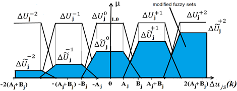
Let I1, I2, I3 and I4be the indices for the input fuzzy sets, each restricted to values of -1 or +1. The output indices, J1 and J2 take values from -2 to +2 and are characterized by the membership functions µΔUjJn (for j, n = 1, 2). The inference engine processes the membership functions of the modified fuzzy sets ΔŨj-2, ΔŨj-1, ΔŨj0, ΔŨj+1and ΔŨj+2, which are obtained through the Larsen product operation. These modified sets are visually identified by the blue-colored areas in Figure 3.
Figure 3. Modified output membership functions (MFs)
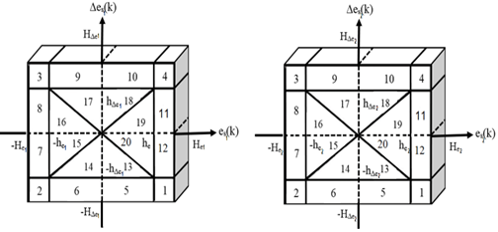
Figure 4. Scaled inputs plane
The scaled input plane region in Figure 4 shows the top view of the three-dimensional plot with the axes es(k), ∆es(k), and µ, representing all possible combinations of each input variable, respectively es1(k), ∆es1(k), es2(k), ∆es2(k). The control law corresponding to each region of the scaled input plane is shown in Figure 4.
The defuzzification part uses the Centre of Sums (CoS) method to calculate the value of scaled output; it is given by [19]:
$\Delta u_{j s}^*(k)=\frac{\sum_{l=1}^5 A\left(\mu_{R l}\right) C\left(\mu_{R l}\right)}{\sum_{l=1}^5 A\left(\mu_{R l}\right)}$ (6)
where, A(µRl) and C(µRl) are respectively the area and centroid of lth inferred output membership function of jth output. The stability of this simplification approach has been demonstrated and discussed at length in the works [13, 14].
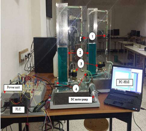
In current specialized literature, many works deal with control strategies for MIMO systems, particularly TITO systems [20, 21]. The following section offers a brief description of the physical system underpinning our application-specifically, a coupled-tanks rig that enables simultaneous level and flow control experiments. The Level/Flow coupled tanks unit consists of a pumping subsystem equipped with DC motor pumps, electrical proportional control valve (1), solenoid valve used to enable tank coupling (3), analog level sensors (4) used for each level column (2) as shown in Figure 5. The functional study of the various indications of sensors and actuators constituting this control unit allowed us to structure the sequencing security model that will be established in a high-priority interrupt routine.
Figure 5. Experimental test bench components
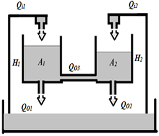
Figure 6. Two-tank coupled system
The mathematical description of the coupled two-tank system's dynamic behavior is presented in Figure 6.
$\begin{aligned} A_1\left(\frac{d\left(H_1+h_1\right)}{d t}\right) & =\left(Q_{i 1}+q_1\right)-c_1 \sqrt{H_1+h_1} \\ & -c_3 \sqrt{\left(H_1-H_2\right)+\left(h_1-h_2\right)}\end{aligned}$ (7)
where, H1 and H2 are the liquid levels to control, and Qi1 and Qi2 represent the input flow of each column.
$\begin{aligned} A_2\left(\frac{d\left(H_2+h_2\right)}{d t}\right) & =\left(Q_{i 2}+q_2\right)-c_2 \sqrt{H_2+h_2} \\ & -c_3 \sqrt{\left(H_1-H_2\right)+\left(h_1-h_2\right)}\end{aligned}$ (8)
With
$Q_{o 1}=c_1 \sqrt{H_1}, Q_{o 2}=c_2 \sqrt{H_2}, Q_{o 3}=c_3 \sqrt{H_1-H_2}$
where H1, H2, A1, A2, are respectively the level and the cross-sectional area of each level column (A1= A2 = 100 cm2), Qi1, Qi2, are input flow, Qo1, Qo2, are output flow, Qo3 is interaction rate of the columns, h1, h2 are variation of level, q1, q2 output flow variation and c1, c2, c3 are valve discharge coefficients, respectively c1 = c2 =2.6, c3 =1.5. The mathematical model derived from Eqs. (7) and (8) is used in the simulation phase to determine the parameters of the simplified fuzzy controller that will be implemented in a Siemens S7-300 PLC equipped with a 314-2DP central processing unit (CPU) for real-time control of the levels of the coupled tank unit. The inputs and outputs of the unit are respectively the valves control Voltage VEv [volts] and the level sensors voltage VL [volts].
The control system employed in this study is built around a highly modular Siemens S7-300 PLC (Figure 3), which is programmed to monitor, control, and analyze sequential operations so as to ensure safe system functioning. The fuzzy system described in Section 2 will be implemented on this PLC using the STEP 7 software environment with ladder logic programming.
The control system is built around a Siemens S7-300 PLC, equipped with a 24V/2A power supply and a 314-2DP CPU. The module configuration includes an MPI/DP communication processor for program transfer and human machine interface (HMI) connectivity, 24 digital inputs, 16 digital outputs, and a dedicated analog I/O module. This analog module provides 5 input and 2 output channels with a ±10V range and 12-bit resolution. The input variables for the implemented fuzzy logic block are two bipolar voltages, which are acquired from the analog input addresses PIW752 and PIW754. The computed output voltages are applied to the analog output module, specifically at addresses PQW752 and PQW754. The main program implements a simplified fuzzy controller architecture. During every acquisition cycle, the input voltages are first scaled, after which their membership degrees for the corresponding fuzzy sets are calculated. The inference and defuzzification blocks are then applied to determine the final output voltages, which are subsequently transferred to the analog outputs at PQW752 and PQW754. Set-point variables are defined using virtual sliders on the HMI. The process feedback, consisting of level responses from the sensors, is read by the controller through two channels of the PLC's analog input module. As detailed in this study [14], the fuzzy controller's input-output relationships are defined using the algebraic product for the AND operator, the bounded sum for the OR operator, and the feedback product for inference. Finally, the CoS method is used for defuzzification. The resulting crisp value of the scaled output is given by Eq. (6), as presented in this study [19].
$\begin{gathered}A\left(\mu_{-2}\right)=0.5\left(A_j+B_j\right) \mu_{-2} ; A\left(\mu_{+2}\right)=0.5\left(A_j+B_j\right) \mu_{+2} \\ A\left(\mu_{-1}\right)=\left(A_j+B_j\right) \mu_{-1} ; A\left(\mu_{+1}\right)=\left(A_j+B_j\right) \mu_{+1} \\ A\left(\mu_0\right)=\left(A_j+B_j\right) \mu_0\end{gathered}$
And
$\begin{gathered}C\left(\mu_{-2}\right)=\frac{-5\left(A_j+B_j\right)^2-A_j B_j}{3\left(A_j+B_j\right)} ; C\left(\mu_{+2}\right)=\frac{-5\left(A_j+B_j\right)^2-A_j B_j}{3\left(A_j+B_j\right)} \\ C\left(\mu_{-1}\right)=-\left(A_j+B_j\right) ; C\left(\mu_{+1}\right)=\left(A_j+B_j\right) \\ C\left(\mu_0\right)=0\end{gathered}$
where, Ajand Bj are the linguistic output values associated with the modified output membership functions depicted in Figure 3. The output value is conditioned for the analog module using the standard unscale function (FC106), which converts it to a proportional integer value in the range 0 to 27648. This value is then written to the output registers at PQW752 and PQW754. This approach offers the key advantage of simple and efficient integration within the PLC programming framework.
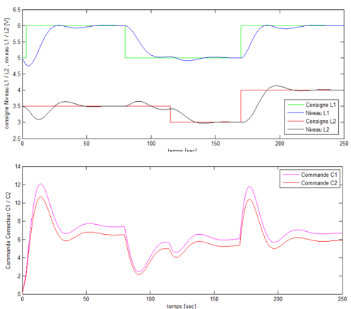
This part presents the simulation and the PLC-based experimental results for the simplified TITO fuzzy controller. The algorithm was first developed in MATLAB/Simulink, with simulation results shown in Figure 7.
Figure 7. Simulation results
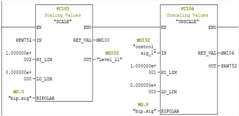
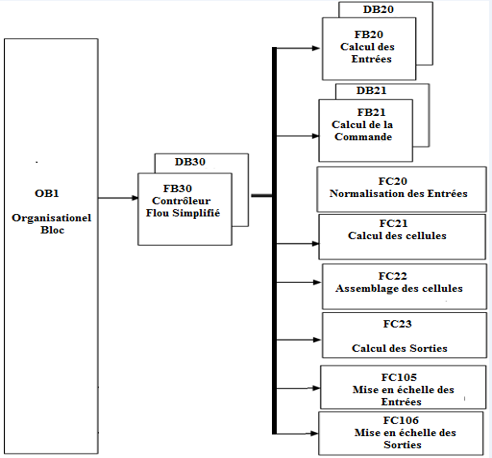
The simulation results demonstrate that the mathematical model of the simplified fuzzy TITO controller ensures system stability, achieves zero steady-state error, and effectively attenuates the interaction effects between the system outputs. The experiment shows the interactive dynamic behavior between the levels of the two coupled reservoirs by controlling the level of each reservoir subject to a different setpoint. In other words, we have applied several set-point tracking. The capacity of the program memory needed to implement this simplest non-linear fuzzy controller on the PLC is 33206 bytes. The CPU in our PLC works firstly by scanning the main programming block called organization block1 (OB1) programmed in ladder diagram (LAD), used to perform inputs/outputs handling, data conversions and normalizations. The structured control language (S7-SCL) is adopted to guarantee programming flexibility, while the FB and FC blocks are tasked with executing the various calculations. Larsen's method achieves a maximum with the OR operator and a minimum with the AND operator. The result in each rule, introduced by the THEN operator that links the membership factor of the condition with the membership function of the output variable by the AND operator, is realized by forming the product. The organizational block (OB1) executes the FB23 fuzzy controller block and all the pre-programmed functions associated with this block cyclically without interruption and terminates its execution cycle by normalizing the input and output signals of the measurement in the FC105 and FC106 scaling blocks as shown in Figure 8.
Figure 8. Conditioner function block FC105, FC106
The scale function FC105 takes an integer value and converts it to a real value expressed in physical units, between a lower limit (Lo_Lim) and an upper limit (Hi_Lim). The unscale function FC106 takes a real input value expressed in physical units and converts it to an integer value. The first step in the controller implementation is the calculation of its input variables, namely the first error e1, its derivative ∆e1, the second error e2 and its derivative ∆e2. These four inputs are computed within block FB20. Normalization gains Ge1, Ge2, G∆e1, G∆e2 are used at the respectively input e1, e2 and ∆e1, ∆e2 of the simplified fuzzy controller programmed in function block FC20. They allow the sensitivity of the fuzzy controller to be changed without changing its structure. The cell calculation is implemented in FC21, where each cell is determined as a function of the respective error and its derivative. Based on the subspaces previously illustrated in Figure 4, the corresponding cell is assigned an integer value between 1 and 9. The assembly of the previously determined cells is implemented in function block FC22. This block combines the two cell values obtained from FC21 to produce a two-digit integer between 11 and 99, representing the composite cell index. The function FC23 calculates the fuzzy controller outputs ∆u1s, ∆u2s, which are the control variations as a function of the global cell using the parameters he1, he2, h∆e1, h∆e2, s12, s21, A1, B1, A2, B2 given in Table 1 and the inputs e1s(k), ∆e1s(k), e2s(k), ∆e2s(k). Finally, the functional block FB21 calculates the commands u1s and u2s, which will be applied to the experimental unit by performing the following operations:
$\begin{aligned} & u_{1 s}(k)=u_{1 s}(k-1)+\Delta u_{1 s}(k) \\ & u_{2 s}(k)=u_{2 s}(k-1)+\Delta u_{2 s}(k)\end{aligned}$ (9)
The control algorithm is coded across three separate function blocks. FB30 contains the fuzzy logic controller, FB20 processes the input calculations, and FB21 derives the control signal using its associated instance data blocks (DB30, DB20, and DB21). These blocks are supported by four function calls (FCs): FC20 performs input normalization, while FC21 and FC22 handle cell computation and assembly tasks. The final output control signal is generated by FC23. Both SCL and LAD programming languages are utilized in the implementation. The overall controller architecture is depicted in Figure 9.
Figure 9. PLC’s program structure for simplest nonlinear fuzzy TITO PI controller
Figure 10. Experimental results of a PLC-based nonlinear fuzzy PI controller
The experimental results of the simplified nonlinear fuzzy TITO PI controller shown in Figure 10 present a stable output response with good tracking. It also validates our implementation approach. The experimental results obtained give an output signal with a rise time (Ts) of 12 s without static error, or overshoot and which stabilises around the value for each setpoint volt.
According to Figure 10, the observed oscillations in the control signals arise from the structure of the control law, which is composed of distinct cells. More precisely, the control output is determined based on the position of the input signals relative to each cell within the input plan illustrated in Figure 4. The parameters of the simplest TITO PI fuzzy controller were obtained through the minimization of the integral of the absolute error (IAE) criterion and are summarized in Table 1.
Table 1. Parameters of the two-term PI fuzzy Controller
|
Parameter |
Value |
|
A1 |
4.000 |
|
A2 |
4.000 |
|
B1 |
4.000 |
|
B2 |
4.000 |
|
s12 |
1.000 |
|
s21 |
-1.000 |
|
E1_MAX |
2.000 |
|
E2_MAX ∆E1_MAX |
3.000 0.050 |
|
∆E2_MAX |
2.000 |
|
HE1 |
3.000 |
|
HE2 |
3.000 |
|
H∆E1 |
1.500 |
|
H∆E2 |
1.500 |
|
hE1 |
1.000 |
|
hE2 |
1.000 |
|
h∆E1 |
0.300 |
|
h∆E2 |
0.300 |
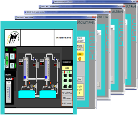
The SIMATIC HMI panel (Figure 11), developed for real-time monitoring and control, allows interaction with the control unit, navigation to other process windows, and graphical display of I/O server data.
Figure 11. Controller human machine interface (HMI) Window
In this study, a simplified nonlinear fuzzy controller is developed and empirically implemented on an industrial PLC for level control in an experimental coupled-tank system. The control hardware comprises a Siemens 314-2DP CPU supplemented with an analog input/output module. The successful deployment of this reduced-complexity fuzzy controller is contingent upon the PLC’s native capabilities for floating-point computation and indirect memory addressing. The controller exhibits cell-dependent output voltage characteristics and operates as a nonlinear variable-gain compensator. Furthermore, the implemented fuzzy PI/PD structure demonstrates commendable performance with respect to both set-point tracking and disturbance attenuation. Foundational framework for subsequent research endeavors aimed at the integration of sophisticated and computationally intensive control strategies within PLC-based industrial architectures.
This work was supported by the Direction Générale de la Recherche Scientifique et du Développement Technologique (DG RSDT).
|
TITO |
Two inputs and two outputs |
|
PLC |
Programmable logic controller |
|
OB1 |
Organization block1 |
|
SCL |
Structured control language |
|
LAD |
Ladder diagram |
|
HMI |
Human machine interface |
|
MFs |
Membership functions |
|
CoS |
Center of Sums |
[1] Bryan, L.A., Bryan, E.A. (1997). Programmable Controllers: Theory and Implementation. Industrial Text Company Publication.
[2] Barker, M., Rawtani, J. (2004). Practical Batch Process Management. Elsevier.
[3] Kamel, K., Kamel, E. (2014). Programmable Logic Controller: Industrial Control. McGraw-Hill.
[4] Berger, H. (2014). Automating with SIMATIC S7-300 Inside TIA Portal: Configuring, Programming and Testing with STEP 7 Professional. John Wiley & Sons.
[5] Lamb, F. (2013). Industrial Automation Hands On. McGraw-Hill.
[6] Dorf, R.C., Bishop, R.H. (2008). Modern Control Systems, Solution Manual.
[7] Allad, M., Charif, M., Fergani, N. (2025). Controllers design for time-delay systems and analysis of robustness limits of iso-damping property with experimental validation. Archives of Control Sciences, 35(4): 835-861. https://doi.org/10.24425/acs.2025.157237
[8] Bettache, F., Bouhedda, M., Abbadi, A. (2022). Implementation of a fuzzy adaptative PI regulator on an S7-300 industrial programmable controller in view of the speed control of an asynchronous machine. Revue Roumaine des Sciences Techniques — Série Électrotechnique et Énergétique, 67(3): 253-258. https://journal.iem.pub.ro/rrst-ee/article/view/114
[9] Yasmine, Z., Karim, B., Razika, B., Younes, B. (2024). Adaptive fuzzy logic control of quadrotor. International Journal of Robotics and Control Systems, 4(4): 2095-2118. https://doi.org/10.31763/ijrcs.v4i4.1583
[10] Xiaojun, B., Xiaozhi, G., Xianlin, H., Tianbao, W. (2006). Analysis of one dimensional and two dimensional fuzzy controllers. Journal of Systems Engineering and Electronics, 17(2): 362-373. https://doi.org/10.1016/S1004-4132(06)60063-7
[11] Bosukonda, M., Kelothu, N. (2011). Mathematical models of the simplest fuzzy two-term (PI/PD) controllers using algebraic product inference. Modelling and Simulation in Engineering, 2011(1): 573715. https://doi.org/10.1155/2011/573715
[12] Kumar, V., Rana, K.P.S., Sinha, A.K. (2011). Design, performance, and stability analysis of a formula-based fuzzy PI controller. International Journal of Innovative Computing, Information and Control, 7(7): 4291-4308.
[13] Mohan, B.M., Sinha, A. (2006). The simplest fuzzy PID controllers: Mathematical models and stability analysis. Soft Computing, 10(10): 961-975. https://doi.org/10.1007/s00500-005-0023-9
[14] Arun, N.K., Mohan, B.M. (2016). Mathematical modelling of the simplest fuzzy two-input two-output proportional integral or proportional derivative controller via Larsen product inference. International Journal of Automation and Control, 10(1): 34-51. https://doi.org/10.1504/IJAAC.2016.075139
[15] Saad, N., Arrofiq, M. (2012). A PLC-based modified-fuzzy controller for PWM-driven induction motor drive with constant V/Hz ratio control. Robotics and Computer-Integrated Manufacturing, 28(2): 95-112. https://doi.org/10.1016/j.rcim.2011.07.001
[16] Yunan, A., Ali, M. (2020). Study and implementation of the fuzzy Mamdani and Sugeno methods in decision making on selection of outstanding students at the South Aceh polytechnic. Jurnal Inovasi Teknologi dan Rekayasa, 5(2): 152-164. https://doi.org/10.31572/inotera.Vol5.Iss2.2020.ID127
[17] Sun, K., Song, Y.M., Feng, G.C. (2009). The application of the fuzzy controller based on PLC in sewage disposal system. In 2009 International Conference on Artificial Intelligence and Computational Intelligence, Shanghai, China, pp. 154-158. https://doi.org/10.1109/AICI.2009.403
[18] Song, Y., Bi, Z., Liu, K. (2007). The PLC system of egg powder treatment based on fuzzy control algorithm. In Fourth International Conference on Fuzzy Systems and Knowledge Discovery (FSKD 2007), Haikou, China, pp. 530-534. https://doi.org/10.1109/FSKD.2007.580
[19] Drainkov, D., Hellendoorn, H., Reinfrank, M. (1993). An Introduction to Fuzzy Control. Springer_Verlag, Berlin.
[20] Navrátil, P., Pekař, L., Matušů, R. (2019). Control of a multivariable system using optimal control pairs: A quadruple-tank process. IEEE Access, 8: 2537-2563. https://doi.org/10.1109/ACCESS.2019.2962302
[21] Roy, P., Roy, B.K. (2016). Fractional order PI control applied to level control in coupled two tank MIMO system with experimental validation. Control Engineering Practice, 48: 119-135. https://doi.org/10.1016/j.conengprac.2016.01.002