Sadi Yassin | Mesri Mokhtaria | Saddam Bensaoucha | Mohamed Benghanem*
© 2026 The authors. This article is published by IIETA and is licensed under the CC BY 4.0 license (http://creativecommons.org/licenses/by/4.0/).
OPEN ACCESS
This work presents a control-oriented solution to the power dead-zone problem in fixed-frequency Wireless Power Transfer (WPT) systems. A hybrid dual-receiver architecture based on two receiver coils with different geometrical dimensions is introduced and combined with a switching strategy that dynamically selects the optimal receiver via real-time power evaluation. The control approach operates at 100 kHz without frequency tuning or impedance matching, supported by an analytical reflected-impedance interpretation linking power collapse to coil geometry. Validation using a real-time co-simulation platform demonstrates stable 20 W output power regulation and effective dead-zone mitigation across 2 to 16 cm distances, switching seamlessly at 9 cm. Furthermore, the proposed control strategy demonstrates robust operation against transmission distance variations, validated through transient analysis under extreme coupling conditions by explicitly accounting for non-ideal switching behavior.
power-based switching control, fixed-frequency operation, hybrid dual-receiver architecture, magnetic resonance coupling, power dead zone
Wireless Power Transfer (WPT) has become a key enabling technology for contactless energy delivery across a wide range of applications, including consumer electronics, implantable medical devices, electric vehicles, and autonomous systems such as drones and Unmanned Aerial Vehicles (UAVs) [1-4]. By eliminating physical connectors, WPT improves system reliability, safety, and user convenience, while enabling power delivery in sealed or harsh environments. However, practical WPT systems are inherently subject to variations in transmission distance, coil misalignment, and receiver positioning. These variations significantly affect magnetic coupling conditions and, consequently, the delivered power. In fixed-frequency resonant WPT systems, maintaining stable power delivery over a wide operating range remains particularly challenging. Under certain spatial configurations, the system may remain energized while delivering negligible power to the load, a phenomenon commonly referred to as the power dead zone. This limitation poses a serious obstacle for real-world deployment, especially in applications requiring reliable and uninterrupted charging.
To mitigate power degradation in resonant WPT systems, extensive research has focused on the frequency splitting phenomenon, which occurs under strong magnetic coupling between transmitter and receiver coils [5-7]. Existing solutions can be broadly categorized into frequency-tracking techniques, impedance-matching methods, and multi-coil architectures. Frequency-tracking approaches dynamically adjust the operating frequency to follow the shifted resonant peaks, enabling power recovery under varying coupling conditions [8-14]. However, this continuous frequency variation inherently violates the strict bandwidth limitations of Industrial, Scientific, and Medical (ISM) bands and severely complicates the control design. Impedance-matching techniques attempt to suppress frequency splitting by restoring optimal load conditions through tunable capacitor networks or adaptive matching circuits [15-20]. Rather than resolving the issue efficiently, their reliance on bulky active circuitry introduces unwanted switching losses and substantially increases the overall system footprint and cost. Multi-coil architectures have also been proposed to enhance robustness against coupling variations [21, 22]; however, they typically rely on complex intermediate repeater coils or active tuning matrices. To clearly distinguish from these approaches, the novelty of this work lies in a concentrically nested dual-coil configuration that entirely avoids active impedance matching or repeater coils. Unlike traditional multi-coil setups that suffer from frequency splitting at close ranges, the proposed architecture inherently suppresses mutual inductance surges by dynamically switching to a geometrically smaller receiver coil.
Despite these advances, fixed-frequency WPT systems continue to experience severe power degradation under certain coupling conditions. Depending on spatial alignment and transmission distance, the mutual inductance between the transmitter and receiver may become either excessively high or excessively low. In both cases, the reflected impedance seen by the transmitter deviates significantly from its optimal value, leading to a collapse in delivered power [23]. Such operating points define a power dead zone, where conventional single-receiver architectures fail to ensure usable power transfer despite strong magnetic interaction [24, 25]. Existing mitigation strategies violate fixed-frequency constraints, require bulky active circuitry, or sacrifice compactness. Therefore, there is a clear need for a low-complexity, compact solution capable of eliminating power dead zones while strictly maintaining fixed-frequency operation.
To address this challenge, this paper proposes a hybrid dual-receiver WPT architecture designed to eliminate power dead zones under fixed-frequency operation. The proposed system integrates two receiver coils with intentionally different geometrical dimensions in a compact nested configuration, leveraging their complementary coupling characteristics across short and long transmission distances. A power-based switching strategy dynamically selects the optimal receiver through real-time evaluation of the delivered output power, without requiring frequency tuning or active impedance matching. This approach is supported by an analytical reflected-impedance interpretation that directly links power collapse to mutual inductance and coil geometry. A time-multiplexed evaluation scheme is introduced to ensure accurate steady-state power assessment while suppressing cross-coupling interference. The proposed architecture is validated using a real-time co-simulation framework combining electromagnetic field analysis and Python-based control, demonstrating stable and continuous power delivery over a wide range of coupling conditions.
The remainder of this paper is organized as follows. Section 2 presents the theoretical analysis and physical interpretation of the power dead zone phenomenon in fixed-frequency WPT systems. Section 3 introduces the proposed hybrid dual-receiver architecture and the associated power-based control strategy. Section 4 discusses the simulation framework and evaluates system performance under varying coupling conditions, including transient behavior at extreme distances and non-ideal switch models considered in the simulations. Section 5 concludes the paper and outlines future research directions.
To theoretically quantify the power dead zones identified previously, this section analyzes the magnetic coupling and system modeling.
2.1 Geometrical modeling of the Wireless Power Transfer system
The fundamental limitation of conventional WPT systems is that a single receiver coil cannot deliver sufficient power over a wide range of transmission distances. Large receiver coils experience strong magnetic coupling at short distances, which induces the frequency splitting phenomenon and severely degrades delivered power. In contrast, small receiver coils exhibit weak mutual coupling at longer distances, resulting in insufficient received power. This inherent trade-off motivates the use of a hybrid receiver architecture capable of maintaining stable power delivery across varying coupling conditions.
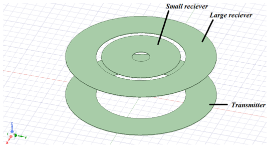
Figure 1 shows the Ansys Maxwell 3D model of the proposed transmitter and nested dual-receiver architecture. The physical configuration consists of a large primary receiver coil and a smaller auxiliary receiver coil concentrically embedded within it, enabling complementary coupling characteristics over different transmission distances.
Figure 1. ANSYS Maxwell 3D model of the transmitter and the nested dual-receiver architecture
The geometrical and electromagnetic parameters of the transmitter and nested receiver coils are summarized in Table 1, including the inner and outer diameters, number of turns, and calculated self-inductance values.
Table 1. Geometrical and electromagnetic parameters of the designed transmitter and nested receiver coils
|
Parameter |
Symbol |
$R_{x 1}$ |
$R_{x 2}$ |
$T_x$ |
Unit |
|
Inner Diameter |
$D_{i n}$ |
100 |
20 |
100 |
mm |
|
Outer Diameter |
$D_{o u t}$ |
168 |
88 |
168 |
mm |
|
Number of Turns |
$N$ |
20 |
20 |
20 |
- |
|
Coil Width (radial) |
- |
34 |
34 |
34 |
mm |
|
Wire Thickness |
$h$ |
1.2 |
1.2 |
1.2 |
mm |
|
Self-inductance |
$L$ |
75.37 |
19.06 |
75.37 |
μH |
The parameters, presented in Table 1, quantitatively define the physical structure of the proposed system and form the basis for establishing its equivalent electrical model. Due to the axial symmetry of the considered coil geometry and the absence of misalignment, a 2D axisymmetric electromagnetic model is adopted for the simulations, while the 3D illustration in Figure 1 is provided solely for visualization purposes.
The magnetic coupling between the transmitter and receiver coils is characterized by the mutual inductance $M$, which depends on the coil dimensions and the transmission distance [26]:
$M(d)=\frac{\mu N_T N_R r_T^2 r_R^2}{\left(r_T^2+r_R^2+d^2\right)^{3 / 2}}$ (1)
Here, $\mu_0$ is the permeability of free space, $N_T$ and $N_R$ denote the number of turns of the transmitter and receiver coils, respectively, $r_T$ and $r_R$ are the coil radii, and $d$ represents the transmission distance. This expression highlights the strong dependence of the coupling strength on both coil radius and separation distance. In particular, larger receiver coils exhibit a rapid increase in mutual inductance as the distance decreases, which plays a critical role in the emergence of over-coupling effects under fixed-frequency operation.
2.2 Received power equation
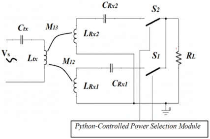
Based on the parameters listed in Table 1, the equivalent electrical circuit of the proposed hybrid WPT system is established, as shown in Figure 2. A series-series (SS) compensation topology is adopted, where the compensation capacitors $\left(C_{t x}, C_{r x 1}, C_{r x 2}\right)$ are connected in series with the transmitter and receiver coils to cancel reactive omponents at the resonant frequency $f_0$, thereby ensuring maximum active power transfer to the load.
Figure 2. Equivalent resonant circuit of the proposed system
The steady-state electromagnetic interaction and power flow within the resonant circuit are mathematically described by the simplified impedance matrix shown in Eq. (2). This formulation provides a systematic framework for analyzing the electrical behavior of the transmitter-receiver system under different magnetic coupling conditions.
$\left[\begin{array}{c}V_s \\ 0\end{array}\right]=\left[\begin{array}{cc}Z_s & j w M_{1 i} \\ j w M_{1 i} & Z_i\end{array}\right]\left[\begin{array}{c}I_s \\ I_i\end{array}\right]$ (2)
In Eq. (2), $V_s$ denotes the source voltage amplitude. The variable $I_s$ explicitly represents the primary source current (transmitter current), while $I_i$ represents the induced secondary current flowing in the active receiver coil (i = 1 for the large coil, and i = 2 for the small coil). The terms $Z_S$ and $Z i$ correspond to the self-impedances of the transmitter and receiver, and $M_{1 i}$ represents the mutual inductance between them.
This formulation allows the system behavior to be analyzed using the concept of reflected impedance, Zref,i, which represents the impedance of the receiver as seen from the transmitter side. The reflected impedance is the key physical parameter governing the frequency splitting phenomenon in strongly coupled resonant WPT systems [27, 28].
$Z_{\text {ref}, i}=\frac{\left(w M_{1, i}\right)^2}{Z_i}$ (3)
where, $\omega=2 \pi f_0$ defines the angular operating frequency. By substituting the reflected impedance $Z_{\text {ref}, i}$ into Kirchhoff's voltage law for the primary circuit, the total input impedance limits the primary source current $I_s$. Consequently, the output power $P_{\text {out}, i}$ delivered to the load is expressed as:
$P_{\text {out }, i}=\underbrace{\left|\frac{V_S}{Z_s+Z_{\text {ref }}}\right|^2}_{\text {square Source current }} \operatorname{Re}\left\{Z_{\text {ref }, i}\right\} \frac{R_L}{R_L+R_i}$ (4)
where, $R_L$ represents the equivalent load resistance, and $R_i$ is the internal parasitic resistance of the active receiver coil ($R_1$ or $R_2$). At the resonance frequency, Eq. (4) becomes:
$P_{\text {out}, i}=\left(\frac{V_S}{R_S+\frac{\left(w M_{1 i}\right)}{R_i+R_L}}\right)^2 \frac{\left(w M_{1 i}\right) R_L}{\left(R_i+R_L\right)^2}$ (5)
Here, $R_s$ denotes the equivalent source resistance accounting for the inherent conduction and parasitic losses of the transmitter-side power source and its driving circuitry.
2.2.1 Dead zone identification
From the received power expression, it can be seen that the reflected impedance increases proportionally to the square of the mutual inductance.
At the resonant frequency $\omega_0$, the secondary impedance becomes purely resistive, and the reflected impedance $Z_{\text {ref}, i}$ is entirely real. This real part, denoted as the reflected resistance $R_{r e f, i}=\operatorname{Re}\left\{Z_{r e f, i}\right\}$, is given by:
$R_{\text {ref}, i}=\left(\omega_0 M_{1 i}\right)^2 /\left(R_L+R_i\right)$ (6)
According to the maximum power transfer theorem, the delivered power peaks at a critical mutual inductance $M_c$, which occurs when the reflected resistance exactly matches the primary equivalent source resistance ($R_{\text {ref}, i}=R_s$). This allows us to analytically define the critical coupling condition:
$M_c=1 / \omega_0 \sqrt{\left(R_L+R_i\right) R_S}$ (7)
The power dead zone emerges when the transmission distance decreases further, pushing the system into the overcoupled regime where $M_{1 i}>M_c$. Under this specific condition, $R_{\text {ref }, i}$ grows quadratically with $M_{1 i}$ and heavily dominates the total input impedance $R_{\text {ref}, i} \gg R_s$. Consequently, the primary source current is severely choked $\left(I_s \approx \frac{V_s}{R_{\text {ref}, i}} \propto 1 / M_{1 . i}^2\right)$, causing the output power to plummet as $P_{\text {out}, i} \propto 1 / M_{1 i}^2$. This mathematical derivation proves that the dead zone is not a vague spatial phenomenon, but a direct consequence of a severe impedance mismatch driven by excessive mutual coupling under a strict fixed-frequency constraint.
Table 2. Simulation parameters and design specifications
|
Parameter |
Symbol |
Value |
Unit |
|
Resonance Frequency |
$f_0$ |
100 |
kHz |
|
Source Voltage |
$V_s$ |
12 |
V |
|
Primary Inductance |
$L_{t x}$ |
75.37 |
uH |
|
Transmitter Capacitor |
$C_{t x}$ |
133 |
nF |
|
Large receiver Capacitor |
$C_{r x 1}$ |
133 |
nF |
|
Small receiver Capacitor |
$C_{r x 2}$ |
33.6 |
nF |
|
Load Resistance |
$R_L$ |
10 |
Ω |
To evaluate the proposed hybrid system, the operational characteristics are analyzed at a unified resonance frequency of $f_0$ = 100 kHz. This design choice is fundamental to eliminating reactive power components, allowing the system to be modeled as a purely resistive network at the switching instances. The physical and electrical parameters used in the Maxwell and Python-based simulations are detailed in Table 2. The compensation capacitors required to achieve resonance for each coil are calculated using the following resonance condition:
$C_{R x i}=\frac{1}{\left(2 \pi f_0\right)^2 L_i}$ (8)
where, $L_i$ represents the self-inductance of the transmitter or receiver.
The system parameters are selected based on practical engineering trade-offs. The 100 kHz operating frequency optimally balances coil size and efficiency; lower frequencies would require bulky coils, whereas higher frequencies increase inverter switching losses and parasitic AC losses. Furthermore, the switching point is dynamically determined by the physical intersection of the power profiles of the two receivers, marking the optimal transition boundary between the over-coupled and under-coupled regime.
The analysis begins with the magnetic behaviour shown in Figure 3, which illustrates the variation of mutual inductance with the transmission distance.
Figure 3. Mutual inductance versus transmission distance
The large receiver (blue curve) exhibits an exponential increase in coupling as the receiver approaches the transmitter. In the deep near-distance region $(d=2 \mathrm{~cm})$, $M_{12}$ rises to approximately 35 μH. This excessive value is the primary cause of system instability, a phenomenon that is significantly exacerbated when the transmitter and receiver coils are symmetrical (identical in size). Conversely, the small receiver (red curve) maintains a stable and moderate profile, with $M_{13}$ remaining below 10 μH even at the closest proximity. This demonstrates that decreasing the receiver's radius effectively mitigates the over-coupling problem by limiting the mutual inductance profile. The Maxwell simulations, along with the fixed electrical parameters summarized in Table 2, collectively determine the system's power delivery performance. This interaction is fundamental in explaining the power collapse observed in Figure 4, where the excessively high mutual inductance of the large receiver at close distances triggers an impedance surge that exceeds the source driving capability, leading to the dead zone phenomenon, as presented in previous work.
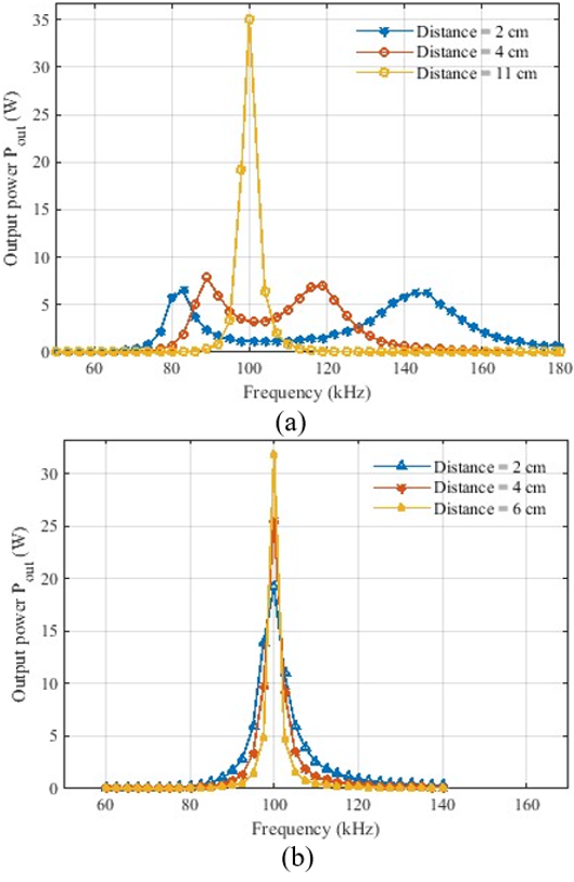
Figure 4. Output power $P_{\text {out}}$ as a function of frequency for (a) the large receiver and (b) the small receiver at different transmission distances
The impact of these coupling profiles on power transfer stability is evident in the frequency response curves in Figure 4(a) and (b). Frequency bifurcation at 2 cm severely attenuates the response at 100 kHz, preventing power transfer. At a close range of 2 cm, the frequency response of the large coil splits into two sidebands, leaving a deep valley exactly at the 100 kHz operating point. This confirms that the large coil is incapable of transferring power at the designed frequency in this region as shown in Figure 4(a). In contrast, the small coil exhibits a robust single-peak response centered at 100 kHz across all distances as shown in Figure 4(b).
The observed performance discrepancy is directly explained by the mathematical derivation presented in Eqs. (4) and (5). At close distances, the mutual inductance of the large receiver, $M_{12}$, becomes excessively high, causing $Z_{r e f, 2}$ to increase drastically. Since $Z_{\text {ref}}$ appears in the squared denominator $\left|Z_S+Z_{\text {ref}, i}\right|^2$, this impedance surge chokes the primary current Is, causing the output power to collapse (the dead zone). The mutual inductance of the small receiver, $M_{13}$ remains lower.
Consequently, $Z_{r e f, 2}$ stays within the optimal range (impedance matching region), maintaining a sufficient source current and ensuring stable power transfer.
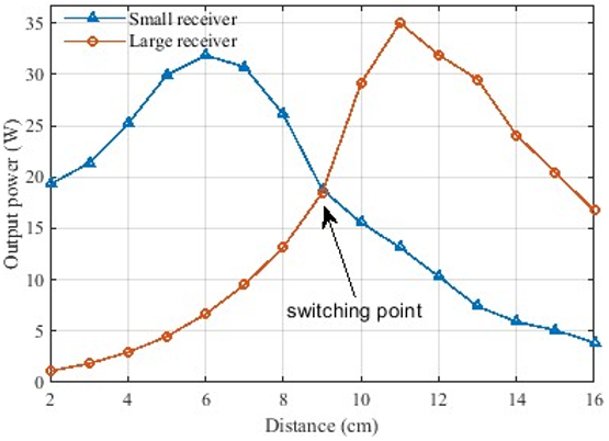
Figure 5 highlights the necessity of the proposed hybrid receiver architecture. The standalone large receiver (red curve) shows a pronounced power dead zone at short transmission distances (d < 6 cm) due to the frequency splitting phenomenon. In contrast, the standalone small receiver (blue curve) effectively covers this near-distance region but delivers from reduced power delivery capability at longer distances because of weak magnetic coupling.
The intersection point at approximately d = 9 cm demonstrates a clear complementary relationship between the two receivers. By switching between the large and small receivers based on the coupling condition, the proposed hybrid system maintains a continuous and high output power profile across the entire charging range, effectively eliminating the power dead zone.
Figure 5. Output power vs. distance highlighting the optimal switching point
To dynamically overcome the coupling limitations identified in the theoretical analysis, we propose the following power-based control algorithm.
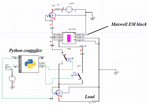
The complete co-simulation environment, which integrates the finite element model developed in Ansys Maxwell with the circuit schematic implemented in Ansys Twin Builder and interfaces with a Python-based control script, is illustrated in Figure 6. A transient co-simulation framework is used to accurately capture the dynamic interaction between the magnetic resonant coupler and the associated circuit-level power interface.
Figure 6. Schematic diagram of the co-simulation framework
Within this framework, Ansys Maxwell is used for electromagnetic field modeling, while Ansys Twin Builder (Simplorer) is employed for circuit-level analysis. A Python-based control script is embedded within the simulation loop to emulate a real-time digital controller. To evaluate the proposed control strategy at the system level, the receiver selection mechanism is implemented using controlled hysteresis-based switches with finite on-state resistance. The proposed algorithm is position-agnostic and operates without explicit knowledge of the coupling intersection point. Instead, it relies on a real-time comparison of the time-averaged output powers $P_{\text {out} 1}$ and $P_{\text {out} 2}$. By computing the mean power value within a predefined steady-state observation window, the algorithm ensures reliable performance evaluation while effectively suppressing transient effects and instantaneous fluctuations.
The optimal receiver path is selected using a simple maximum criterion, max ($P_{\text {out} 1}$, $P_{\text {out} 2}$), which implicitly determines the appropriate switching instant and guarantees a smooth and stable transition between receivers.
To ensure high measurement accuracy and eliminate electromagnetic interference (EMI) between the nested receiver coils, a strict temporal isolation strategy is adopted. During each sensing interval, only one receiver coil is energized while the other remains electrically isolated.
This approach effectively suppresses parasitic cross-coupling effects ($M_{23}$) that could otherwise distort the power measurements.
At the start of the simulation, internal storage variables are initialized to accumulate power samples. The algorithm then proceeds through a series of sequential evaluation phases, during which the steady-state output power of each receiver is sampled, averaged, and stored in the controller’s internal memory before the final selection decision is made.
Initialize:
S1 ← 0, S2 ← 0
Initialize memory for $P_{\text {out} 1}$ and $P_{\text {out} 2}$
// Large Receiver Evaluation
Set S1 ← 1, S2 ← 0
Wait until steady state
For t ∈ [1.5 ms, 2 ms]:
Sample output power
Compute $P_{\text {out} 1}$ ← avg (power samples)
Store $P_{\text {out} 1}$
// Small Receiver Evaluation
Set S1 ← 0, S2 ← 1
Wait until steady state
For t ∈ [3.5 ms, 4 ms]:
Sample output power
Compute $P_{\text {out} 2}$ ← avg (power samples)
// Decision Making
If $P_{\text {out} 1}$ ≥ $P_{\text {out} 2}$ then
S1 ← 1, S2 ← 0
$P_{\text {out}}$ ← $P_{\text {out} 1}$
Else
S1 ← 0, S2 ← 1
$P_{\text {out}}$ ← $P_{\text {out} 2}$
End If
From a control theory perspective, the proposed algorithm transforms the highly non-linear spatial coupling problem into a deterministic, finite-state decision process. While traditional continuous-tracking methods are susceptible to instability under spatial perturbations, this algorithm guarantees absolute steady-state stability through a definitive lock-in mechanism. Specifically, at the critical power intersection boundary where conventional hysteresis controllers typically suffer from high-frequency chattering the proposed open-loop evaluation followed by a (hard latch) ensures a single, definitive state transition. This discrete-event control approach renders the system architecturally immune to boundary-induced oscillations, ensuring robust and continuous power delivery across any spatial configuration.
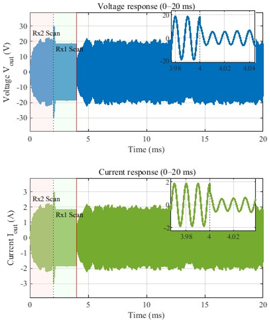
To evaluate the effectiveness of the proposed coil-selection algorithm, the system’s transient and steady-state responses were analyzed at the critical switching distance of 9 cm. As shown in Figure 7, the operation is divided into three distinct phases:
System identification phase (0 to 4 ms): During this interval, the algorithm rapidly scans the available receivers. From 0 to 2 ms , small receiver $\left(R_{x 2}\right)$ is activated, followed by the large receiver $\left(R_{x 1}\right)$ from 2 to 4 ms. The observed fluctuations in the output voltage ($V_{\text {out}}$) and current ($I_{\text {out}}$) amplitudes during this phase are result from the diagnostic process used to evaluate the mutual coupling for each coil. The brief inductive spikes at the switching boundaries are inherent to the high rate of change in current $(d i / d t)$ during transitions in inductive power transfer systems. The proposed control strategy introduces a 4 ms diagnostic delay prior to the final receiver selection. This brief sampling window is intentionally incorporated to allow initial electrical transients to settle, ensuring the decision relies strictly on steady-state power values. In practical WPT applications, the mechanical displacement of the receiver is significantly slower than this millisecond-scale electrical evaluation. Consequently, the sensing delay has a negligible impact on the magnetic coupling variations and does not compromise the continuous power delivery or system stability.
Figure 7. Transient voltage and current at switching point
Decision point and seamless transition (at 4 ms): The most critical aspect of the proposed control logic is its stability at the decision-making point. The micro-zoom insets in Figure 7 highlight the transition at 4 ms. The transition to the optimal receiver is achieved seamlessly, with no significant phase distortion or prolonged oscillation.
Steady State Stability (4-20 ms): after the switching instance, the system maintains a quantitatively stable sinusoidal output regulated exactly at a 20 V peak. Specifically, as evidenced by the micro-zoom insets, the output reaches its steady-state with a rapid settling time of less than 0.5 ms and exhibits a negligible voltage amplitude ripple of under 1%. The uniform waveforms confirm successful locking onto the optimal state with zero observed chattering events during the transition, ensuring high-quality power delivery even at the boundary distance. As observed in Figure 7, the output voltage stabilizes with a peak amplitude $V_{\text {peak}}$ of 20 V. This corresponds to an RMS voltage ($V_{r m s}$) of approximately 14.14 V, which, given the 10 $\Omega$ load, results in a steady-state output power of 20 W. This quantitative result aligns with the analytical power-distance curves presented in Figure 8, where the intersection point at d ≈ 9 cm yields the same power level.
This agreement between the time-domain waveforms and the frequency-domain analysis confirms the effectiveness of the proposed switching logic at the critical operating point. To further validate robustness beyond this boundary condition, the system response was also evaluated at two extreme transmission distances (2 cm and 11 cm), representing over-coupled and under-coupled operating conditions.
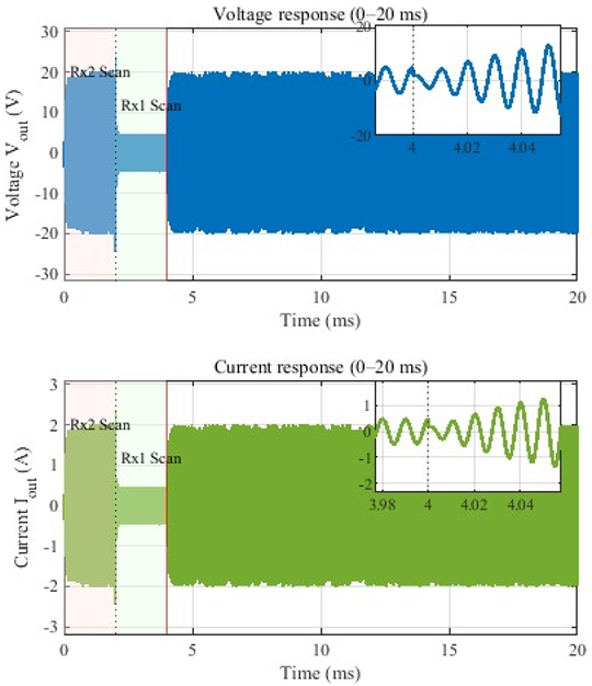
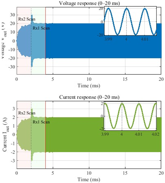
Figure 8 shows the transient voltage and current responses of the proposed system at transmission distances of 2 cm and 11 cm, respectively, representing the extreme over-coupled and under-coupled operating conditions. In both cases, the controller initially performs a time-multiplexed evaluation of the available receiver coils by sequentially activating each path and storing the corresponding time-averaged output power values.
(a)
(b)
Figure 8. Transient voltage and current responses at transmission distances of (a) 2 cm and (b) 11 cm
At a distance of 2 cm, the large receiver experiences severe over-coupling, resulting in significant power reduction, while the small receiver provides a higher and more stable output. After comparing the stored power values, the algorithm directly selects the small receiver ($R_{x 2}$) and latches to this configuration for the remainder of the operation.
Conversely, at a distance of 11 cm, the magnetic coupling is weak, and the small receiver delivers insufficient power. In this case, the stored power comparison prompts the controller to immediately select the large receiver ($R_{x 1}$) as the optimal power transfer path. As shown in both figures, once the decision is made, the selected receiver remains active without further switching, and the voltage and current waveforms converge smoothly to a stable sinusoidal steady state.
This consistent behavior at both extreme distances confirms that the proposed control strategy bases its decisions on stored average power comparisons rather than instantaneous measurements, thus avoiding chattering and ensuring quantitatively robust operation across a wide range of coupling conditions. In this context, robustness is mathematically verified by the system's ability to maintain a guaranteed minimum power delivery threshold of 20 W across the entire 2 cm to 16 cm transmission range, while strictly maintaining a 0% frequency deviation from the 100 kHz resonance point.
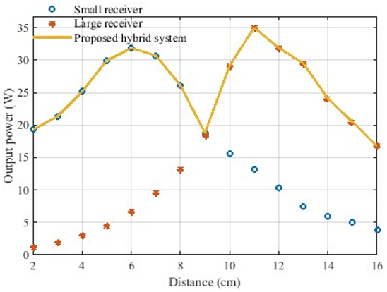
Figure 9 shows the output power versus transmission distance for the standalone large receiver, standalone small receiver, and the proposed hybrid system under fixed-frequency operation.
Large receiver limitations: At close distances (d < 5 cm), the large receiver shows a sharp decline in power, nearly reaching zero. This is known as the power dead zone, caused by the frequency splitting phenomenon.
Small receiver performance: The small receiver provides a stable and high power output in the near-field region (0 to 7 cm), effectively filling the gap left by the large receiver. However, its power decays rapidly beyond 9 cm due to weak coupling.
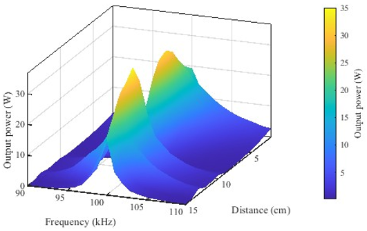
Proposed hybrid system: The orange curve represents the hybrid system controlled by Python. By dynamically switching at the optimal crossover point (approximately 9 cm), the system maintains a continuous and high-power level throughout the entire range, successfully eliminating the dead zone. The proposed hybrid system establishes a continuous power path, ensuring that the delivered power never drops below a critical threshold (approximately 20 W) even at zero distance. This eliminates the power discontinuities typical of single receiver systems, providing a reliable charging profile regardless of transmitter-receiver proximity. Figure 10 illustrates the 3D power profile of the system under the proposed control strategy, mapping the output power (z-axis) as a simultaneous function of operating frequency (x-axis) and transmission distance (y-axis). The color gradient, mapped from dark blue (indicating near-zero power in the dead zones) to yellow (indicating peak power delivery up to 35 W), visually quantifies the energy transfer capability. A defining characteristic of this surface topology is the continuous, unbroken ridge (the yellow crest) that aligns strictly along the fundamental resonant frequency ($f_0$ = 100 kHz) across the entire transmission range.
Figure 9. Output power vs. distance for hybrid and standalone systems
Figure 10. Output power versus distance for standalone and hybrid receiver configurations
Unlike conventional strongly coupled systems where the resonant peak bifurcates, the proposed hybrid switching mechanism effectively suppresses this splitting phenomenon. Consequently, the system maintains a unimodal, high-power response regardless of variations in transmission distance. As shown by this surface, the algorithm renders the system architecturally immune to frequency splitting, thereby eliminating the need for complex and costly frequency-tracking or active impedance-matching circuitry. The locking of the peak power at exactly 100 kHz validates that the control algorithm successfully enforces resonant operation, ensuring a stable and efficient energy link throughout the charging process.
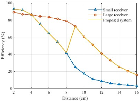
Figure 11 highlights the inherent trade-off between efficiency and power continuity in fixed-frequency WPT systems.
Figure 11. Efficiency versus distance for standalone and hybrid Wireless Power Transfer (WPT) systems
While the proposed hybrid system successfully eliminates the power dead zone, a moderate reduction in overall efficiency is observed when operating with the small receiver compared to the theoretical peak efficiency of the large receiver at optimal distances. This behavior is an intentional design choice, as the large receiver would otherwise deliver near-zero power in the over-coupled region due to frequency splitting. By prioritizing power continuity and fixed-frequency operation over peak theoretical efficiency, the delivery across the entire charging range, which is of greater practical importance for real-world charging applications.
Table 3 summarizes the key performance differences between the standalone receiver configurations and the proposed hybrid system under fixed-frequency operation. The comparison shows that while each standalone receiver is effective over a limited distance range, only the hybrid architecture ensures continuous power delivery across the entire charging range without requiring frequency tuning or active impedance matching.
To transition the proposed hybrid dual-receiver architecture from the co-simulation environment to a physical prototype, several critical engineering considerations must be addressed. Operating strictly at 100 kHz requires the use of wide-bandgap semiconductors, such as Silicon Carbide (SiC) or Gallium Nitride (GaN) MOSFETs, to minimize switching losses and thermal dissipation in the primary inverter. Furthermore, the real-time power evaluation algorithm necessitates a microcontroller equipped with a high-speed Analog-to-Digital Converter (ADC). The sampling window must be tightly optimized to ensure the computation delay remains well below the AC wave period (10 ms), thereby preventing any transient lag during the critical switching event at the 9 cm boundary. Finally, the physical layout of the concentrically nested coils must account for high-frequency skin and proximity effects by utilizing individually insulated Litz wire, ensuring that the intrinsic quality factor remains high for both the primary and auxiliary receivers.
Table 3. Comparative performance evaluation of Large receiver, Small Receiver, and proposed hybrid system
|
Metric |
Standalone Large Receiver |
Standalone Small Receiver |
Proposed Hybrid System |
|
Receiver Size |
Large radius |
Small radius |
Nested (Large + Small) |
|
Operating Frequency |
100 kHz (fixed) |
100 kHz (fixed) |
100 kHz (fixed) |
|
Frequency Splitting at Short Distance |
Severe |
None |
Eliminated |
|
Power Dead Zone |
Present (d < 5-6 cm) |
None |
eliminated |
|
Near-Distance Power (d ≈ 2 cm) |
≈0-2 W |
≈20-32 W |
≈20 W |
|
Mid-Distance Power (d ≈ 9 cm) |
≈20 W |
≈20 W |
≈20 W (seamless switching) |
|
Long-Distance Power (d > 10 cm) |
High (efficient) |
Low (weak coupling) |
High (large Rx active) |
|
Power Continuity Over Distance |
Discontinuous |
Discontinuous |
Continuous |
|
Sensitivity to Coupling Variations |
High |
Low |
Low |
|
Control Requirement |
None |
None |
Simple Python-based switching |
|
Need for Frequency Tracking |
Yes (theoretically) |
No |
No |
|
Need for Active Impedance Matching |
Yes |
No |
No |
|
Overall Suitability for Fixed-Frequency Wireless Power Transfer (WPT) |
Poor |
Limited |
Excellent |
This study successfully proposed and validated a hybrid dual-receiver architecture to eliminate power dead zones in fixed-frequency WPT systems. By combining a concentrically nested coil design with a real-time power-based switching strategy, the system effectively suppresses mutual inductance surges without the need for bulky active impedance matching networks. Co-simulation results demonstrated that the proposed control mechanism maintains a stable output power of 20 W across a 2 cm to 16 cm transmission range, switching seamlessly at the 9 cm critical distance while strictly adhering to a 100 kHz frequency constraint. Regarding physical implementation, while this study isolated the baseline switching logic under ideal alignment, practical misalignments will predictably reduce mutual inductance and shift the optimal switching threshold. Consequently, physical prototyping and an extensive parametric study of coupling variations under misaligned conditions represent the immediate focus of our future experimental work.
[1] Li, S.Q., Mi, C.C. (2015). Wireless power transfer for electric vehicle applications. IEEE Journal of Emerging and Selected Topics in Power Electronics, 3(1): 4-17. https://doi.org/10.1109/JESTPE.2014.2319453
[2] Rayan, B.A., Subramaniam, U., Balamurugan, S. (2023). Wireless power transfer in electric vehicles: A review on compensation topologies, coil structures, and safety aspects. Energies, 16(7): 3084. https://doi.org/10.3390/en16073084
[3] Liu, Z., Li, T., Li, S.Q., Mi, C.C. (2024). Advancements and challenges in wireless power transfer: A comprehensive review. Nexus, 1(2): 100014. https://doi.org/10.1016/j.ynexs.2024.100014
[4] Jawad, A.M., Jawad, H.M., Nordin, R., Gharghan, S.K., Abdullah, N.F., Abu-Alshaeer, M.J. (2019). Wireless power transfer with magnetic resonator coupling and sleep/active strategy for a drone charging station in smart agriculture. IEEE Access, 7: 139839-139851. https://doi.org/10.1109/ACCESS.2019.2943120
[5] Nafiaa, R.E., Yonis, A.Z. (2022). Analysis of frequency splitting phenomenon in WPT for intelligent applications. In 2022 IEEE International Conference on Automatic Control and Intelligent Systems (I2CACIS), Shah Alam, Malaysia, pp. 174-179. https://doi.org/10.1109/I2CACIS54679.2022.9815489
[6] Imura, T., Hori, Y. (2011). Maximizing air gap and efficiency of magnetic resonant coupling for wireless power transfer using equivalent circuit and Neumann formula. IEEE Transactions on Industrial Electronics, 58(10): 4746-4752. https://doi.org/10.1109/TIE.2011.2112317
[7] Hu, W.K., Zhang, B.W., Hu, Y.H., Li, H.X., Han, W. (2025). Maximizing wireless power transfer efficiency at exceptional points. Communications Engineering, 4(1): 105. https://doi.org/10.1038/s44172-025-00445-y
[8] Zhang, R.J., Yuan, H., Rong, M.Z., Ke, W., Liang, C.X., Chu, J.F. (2024). Self-tuning WPT system with constant voltage output under resonance frequency shift. IEEE Transactions on Power Electronics, 39(1): 1713-1722. https://doi.org/10.1109/TPEL.2023.3317389
[9] Tan, P.A., Song, B., Lei, W., Yin, H., Zhang, B. (2023). Decoupling control of double-side frequency tuning for LCC/S WPT system. IEEE Transactions on Industrial Electronics, 70(11): 11163-11173. https://doi.org/10.1109/TIE.2022.3224139
[10] Feng, H.W., Liu, Y.Y., Huang, C.G., Xie, L.B., Qi, B. (2023). Real-time frequency adaptive tracking control of the WPT system based on apparent power detection. International Journal of Intelligent Systems, 2023(1): 1390828. https://doi.org/10.1155/2023/1390828
[11] Liu, Y.Y., Liu, F., Feng, H.W., et al. (2022). Frequency tracking control of the WPT system based on fuzzy RBF neural network. International Journal of Intelligent Systems, 37(7): 3881-3899. https://doi.org/10.1002/int.22706
[12] Chen, F.W., Cui, Y.X., Gao, J.B., Peng, W., Qing, X.D. (2026). Data-based zero-phase angle frequency tracking for series-series compensated WPT systems. IEEE Transactions on Power Electronics, 41(4): 6940-6953. https://doi.org/10.1109/TPEL.2025.3612727
[13] Zhang, Y.M., Kan, T.Z., Yan, Z.C., Mi, C.C. (2019). Frequency and voltage tuning of series-series compensated wireless power transfer system to sustain rated power under various conditions. IEEE Journal of Emerging and Selected Topics in Power Electronics, 7(2): 1311-1317. https://doi.org/10.1109/JESTPE.2018.2871636
[14] Liu, X., Yuan, X.B., Xia, C.Y., Wu, X.J. (2021). Analysis and utilization of the frequency splitting phenomenon in wireless power transfer systems. IEEE Transactions on Power Electronics, 36(4): 3840-3851. https://doi.org/10.1109/TPEL.2020.3025480
[15] Shao, Y.X., Zhang, H., Liu, M., Ma, C.B. (2022). Explicit design of impedance matching networks for robust MHz WPT systems with different features. IEEE Transactions on Power Electronics, 37(9): 11382-11393. https://doi.org/10.1109/TPEL.2022.3165296
[16] Yang, J., Shi, Y., Wei, W.Y., Shen, H. (2020). A wireless power transfer system based on impedance matching network. International Journal of RF and Microwave Computer-Aided Engineering, 30(12): e22437. https://doi.org/10.1002/mmce.22437
[17] Zhang, Y., Feng, Y., Liu, S., Wu, J., He, X.N. (2021). Impedance matching method for 6.78 MHz class-E2-based WPT system. Energies, 14(14): 4289. https://doi.org/10.3390/en14144289
[18] Huang, S.D., Li, Z.Q., Lu, K.Y. (2016). Frequency splitting suppression method for four-coil wireless power transfer system. IET Power Electronics, 9(15): 2859-2864. https://doi.org/10.1049/iet-pel.2015.0376
[19] Sun, P., Cai, J., Wu, X.S., et al. (2022). Analysis of frequency bifurcation and frequency splitting of IPT system under overcoupling. Energy Reports, 8: 61-72. https://doi.org/10.1016/j.egyr.2022.05.099
[20] Huang, Z.H., Wang, L., Zhang, Y.X., Liu, R.T. (2020). Design of WPT RF power supply based on dual directional coupler and capacitor array impedance matching network. IEEE Access, 8: 68209-68218. https://doi.org/10.1109/ACCESS.2020.2983492
[21] Jun, Y.B., Kim, J., Lee, S.U., et al. (2024). Multiple-split transmitting coils for stable output power in wireless power transfer system with variable airgaps. Energies, 17(16): 4025. https://doi.org/10.3390/en17164025
[22] Afoakwa, S., Jung, Y.B. (2019). Frequency splitting elimination in a multi-coil power transfer system. In 2019 International Conference on Mechatronics, Remote Sensing, Information Systems and Industrial Information Technologies (ICMRSISIIT), Ghana, pp. 1-6. https://doi.org/10.1109/ICMRSISIIT46373.2020.9405831
[23] Koh, K.E., Imura, T., Hori, Y. (2016). Analysis of dead zone in wireless power transfer via magnetic resonant coupling for charging moving electric vehicles. International Journal of Intelligent Transportation Systems Research, 14(3): 152-163. https://doi.org/10.1007/s13177-015-0110-y
[24] Naveed, I., Tan, L.L., Yameen, M.Z., Hussain, A. (2025). Free-positioning wireless power transfer for multiple-receivers using a half-cube shaped transmitting coil. Wireless Power Transfer, 12(1): e021. https://doi.org/10.48130/wpt-0025-0016
[25] Shikauchi, Y., Matsumoto, R., Nagai, S., Fujita, T., Shimizu, O., Fujimoto, H. (2023). Eliminating dead zone in wireless power transfer with repeater coil by power factor control. In 2023 IEEE Wireless Power Technology Conference and Expo (WPTCE), San Diego, CA, USA, pp. 1-6. https://doi.org/10.1109/WPTCE56855.2023.10216172
[26] Rim, C.T., Mi, C.C. (2017). Wireless Power Transfer for Electric Vehicles and Mobile Devices. Hoboken, NJ, USA, IEEE Press Wiley.
[27] Xu, Y.Z., Zhang, Y.X., Wu, T.Z. (2024). Wireless power transfer efficiency optimization tracking method based on full current mode impedance matching. Sensors, 24(9): 2917. https://doi.org/10.3390/s24092917
[28] Machnoor, M., Lazzi, G. (2020). Wireless power transfer: Types of reflected impedances and maximum power transfer theorem. IEEE Antennas and Wireless Propagation Letters, 19(10): 1709-1713. https://doi.org/10.1109/LAWP.2020.3014357