Hien Nguyen Thi Minh* | Chương Trinh Trong | Anh Pham Quang | Thanh Nguyen Vu | Vuong Dang Quoc | Phi Do Chi
© 2026 The authors. This article is published by IIETA and is licensed under the CC BY 4.0 license (http://creativecommons.org/licenses/by/4.0/).
OPEN ACCESS
Synchronous reluctance machines (SynRMs) have emerged as a promising rare-earth-free alternative for electric vehicle traction and industrial drives owing to their robust rotor structure, low cost, and high efficiency. However, high torque ripple remains a major drawback, causing vibration, acoustic noise, and degraded drive performance. This paper presents a comprehensive study on torque ripple reduction in a 2.2 kW, 36-slot/6-pole SynRM using continuous stator slot skewing and discrete rotor step skewing techniques based on harmonic analysis. Two-dimensional finite element analysis (FEA) results show that continuous stator slot skewing with an optimal mechanical angle of 10° reduces torque ripple by over 92% (from 30% to approximately 2.2%), while causing less than 1.5% reduction in average torque. For rotor skewing, a 5-step configuration at 10° mechanical skew angle effectively eliminates the dominant 6th and 12th order harmonics, achieving approximately 65% torque ripple reduction with acceptable average torque penalty. The study confirms that optimal skew design requires careful selection of both skew angle and number of steps to target dominant torque harmonics. The proposed techniques provide practical solutions for developing high-performance, low-ripple SynRMs.
synchronous reluctance motor, torque ripple, stator skewing, rotor step skewing, harmonic elimination, finite element analysis
Synchronous reluctance machines (SynRMs) have attracted increasing interest in modern electric-drive applications because of their simple and magnet-free rotor structure, low rotor losses, high efficiency, and favorable thermal behavior [1, 2]. In contrast to permanent-magnet (PM) based topologies, the SynRM rotor contains neither windings nor PMs, which reduces material cost and alleviates concerns related to rare-earth supply, sustainability, and rotor heating [1]. These advantages make SynRMs promising candidates for industrial drives, traction systems, and other applications where robustness, efficiency, and cost are critical.
Despite these benefits, the torque ripple remains one of the main limitations of SynRM technology [1, 3]. The excessive torque ripple can excite mechanical vibration, acoustic noise, speed oscillation, and current distortion, thereby degrading drive quality and limiting applicability in high-performance systems [1, 2, 4]. From an electromagnetic viewpoint, the torque ripple in SynRMs mainly originates from the interaction between stator magnetomotive force (MMF) space harmonics and the anisotropic rotor geometry created by flux barriers, ribs, and slotting effects [2, 4, 5]. Because the SynRM torque production relies on saliency rather than rotor excitation, the machine is especially sensitive to harmonic content in the air-gap field [3].
Accordingly, many studies have focused on reducing torque ripple through winding optimization, slot-pole selection, flux-barrier shaping, rib placement, and rotor asymmetry [2, 4, 6, 7]. While these approaches can be effective, they often increase design complexity and may require extensive electromagnetic optimization. For this reason, skewing has become one of the most practical and widely used post-optimization techniques for SynRM ripple mitigation [3, 5, 8]. In essence, skewing introduces an axial angular displacement so that different machine slices generate harmonic torque components with different phase angles; when these slice contributions are superimposed, selected harmonics are attenuated, leading to a smoother electromagnetic torque waveform [2, 3, 8, 9].
In the SynRMs, skewing can be implemented either on the rotor or on the stator. The rotor skewing shifts the saliency pattern along the axial direction and is particularly effective in weakening slot-harmonic-induced torque pulsations [5, 8, 9]. The stator skewing, by contrast, directly acts on slotting-related harmonic excitation and can be attractive when rotor manufacturability or mechanical integrity is a concern [10]. Recent results on a skewed-slot ferrite-assisted SynRM showed that skewing the stator slots can markedly reduce harmonic distortion in flux linkage and back-electromotive force (EMF), while simultaneously suppressing torque ripple [10]. Specifically, the reported design reduced total harmonic distortion (THD) of flux linkage from 3.34% to 2.15%, back-EMF from 30.91% to 7.90%, and torque ripple from 28.27% to 0.85% compared with a non-skewed counterpart, illustrating the strong harmonic-filtering effect of axial slot displacement [3, 10].
Skewing is commonly realized in two principal forms: continuous skewing and discrete skewing, also known as step skewing [11]. Continuous skewing rotates the laminations progressively from one end of the stack to the other, which can provide strong ripple suppression but also complicates manufacturing because each lamination must be positioned differently [3, 8]. Discrete skewing divides the stack into a limited number of axial segments, each rotated by a fixed step angle relative to the next, offering a more practical compromise between electromagnetic performance and manufacturability [3, 8, 12, 13].
Traditionally, many SynRM studies have used a skew angle close to one stator slot pitch [3, 5, 12]. This rule is attractive because it often suppresses dominant slot-related harmonics. However, more recent research has shown that the one-slot-pitch rule is not universally optimal [3, 6, 9]. The ideal skew angle depends on the slot-pole combination, rotor topology, dominant torque-ripple harmonics, and the number of axial steps [3, 6]. The study [3] demonstrated that the harmonic-oriented selection of the skew angle can reduce torque ripple by up to 70%, and that two-step skewing is suitable when one harmonic dominates, whereas multi-step skewing is more effective when several large harmonics coexist. Similarly, other studies reported that the optimum skew angle may deviate substantially from one slot pitch and may even lie in the range of 60–80% of slot pitch depending on machine topology [3, 6, 9].
To overcome the limitations of conventional trial-and-error skewing methods, this paper establishes a systematic, harmonic-oriented design approach to minimize torque ripple in a 2.2 kW, 36-slot/6-pole SynRM. By utilizing high-fidelity 2D and 3D finite element analysis (FEA), the spatial harmonic filtering effects of continuous stator slot skewing and discrete rotor step skewing are comprehensively investigated and cross-compared. The core objective is to identify the optimal configuration that yields the highest ripple reduction while preserving the fundamental average torque. The remainder of this paper is organized as follows: Section 2 outlines the theoretical background of torque harmonics and skewing factors; Section 3 presents the detailed FEA simulation results and parametric sensitivity studies; Section 4 evaluates the engineering limitations and industrial feasibility; and Section 5 concludes the paper.
The electromagnetic torque of the SynRM is produced by the difference between d- and q-axis inductances. In the rotor reference frame, the torque can be expressed as [1, 2, 14, 15]:
$T_e=\frac{3}{2} p\left(L_d-L_q\right) i_d i_q$ (1)
where, $p$ is the number of pole pairs, and $L_d$ and $L_q$ are the $d$- and $q$-axis inductances.
The torque ripple in the SynRM can be represented by a Fourier series expansion of the electromagnetic torque waveform [11, 16-18]:
$T_{\text {ripple}, v}\left(\theta_{r, e}\right)=A_v \cdot \cos \left(\frac{\pi}{180} \theta_{r, e} v+\varphi_v\right)$ (2)
where, $\theta_{r, e}$ is the rotor position in electrical degree, $A_v$ is the amplitude of the v-th harmonic of the torque ripple, $\varphi_v$ is the phase shift of torqule waveform and $v=1,2,3 \ldots$. In three-phase SynRMs, the main torqueripple period is typically related to the 60 electrical degree periodicity of the stator MMF distribution, which explains why specific harmonic orders dominate depending on the slot-pole combination and rotor barrier arrangement [3].
To evaluate the torque pulsation performance quantitatively, the Torque ripple ($T_{\text {ripple}}$) is defined as the ratio of the peak-to-peak torque variations to the average electromagnetic torque, expressed as follows [19, 20]:
$T_{\text {ripple}}=\frac{T_{\max }-T_{\min }}{T_{\text {avg }}} \cdot 100 \%$ (3)
where, $T_{\max}$, $T_{\min}$ and $T_{\text {avg}}$ represent the maximum, minimum, and average simulated electromagnetic torque values, respectively.
The purpose of skewing is to reduce the amplitude of the dominant harmonic terms in Eq. (2) by introducing an axial phase shift between different machine slices. This can be achieved either by rotor skewing, where the rotor laminations or axial segments are rotated with respect to each other, or by stator skewing, where the stator slots are axially displaced [3, 5, 8]. In both cases, the harmonic contributions generated by each axial section are no longer in phase, and partial cancellation occurs when the total torque is obtained by axial superposition. This principle explains why skewing is one of the most established ripple-mitigation methods in the SynRM design [3, 5, 8].
The skewing may be implemented as continuous skewing or discrete skewing. In continuous skewing, the angular displacement varies continuously from one end of the axial stack to the other. In discrete skewing, also called step skewing, the stack is divided into N segments, each rotated by a fixed angle relative to the adjacent one [3, 8]. Continuous skewing generally offers smooth harmonic attenuation, but it is more difficult to manufacture. Step skewing is more attractive in practice because it approximates the same physical effect with a limited number of rotor or stator segments [3, 8].
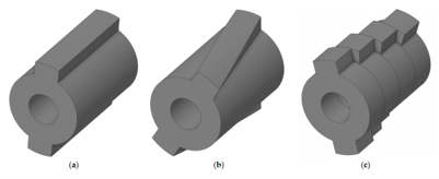
Figure 1. 3D sketches of different types of skew: (a) reference skewless rotor, (b) continuous skew and (c) discrete skew [3]
In rotor skewing, for rotors, due to their complex structure, slot inclination can be achieved by offset lamination of the steel sheets. For rotor inclination, several options can be considered, as in Figure 1. Unlike the stator, due to the complex nature of the rotor's structure, the step-skew method is often used. Unlike traditional tilting methods, the use of step-skew, if not properly designed, can cause problems with magnetic flux leakage between the steps. The pitch of the step rotor depends on the following factors: Pitch angle and number of steps.
The skewing attenuates selected harmonics by introducing an axial angular displacement. For discrete (step) skewing with N steps, the skew angle α (mechanical) for canceling w-th harmonic of the torque ripple wants to be mitigated is given by [3, 15]:
$\alpha=\frac{360^{\circ}}{p N w}$ (4)
where, N is the number of skew steps. Eq. (4) is particularly important because it generalizes the skew-angle selection rule beyond the conventional one-slot-pitch assumption. In other words, the optimum skew angle should be selected from the dominant torque harmonic content, not from a fixed empirical rule alone [3, 6, 9]. In the study [3], the torque was created to include [11]:
$T_{\text {skw}}=T_{\text {avgskew}}+T_{\text {ripple}}$ (5)
The characteristic of medium torque is:
$T_{\text {avgskew}}=\frac{1}{2} \cdot I_s^2 \cdot\left(L_d-L_q\right) \cdot k_{T_{\text {skew }}} \cdot \operatorname{Sin}(2 \cdot \beta)$ (6)
The magnitude of v-th harmonic after skewing is reduced by the skew factor [11, 14]:
$k_{T_{\text {skew}, v}}=\frac{\sin \left(\frac{N \cdot v \cdot \alpha}{2(N-1)}\right)}{N \cdot \sin \left(\frac{v \cdot \alpha}{2(N-1)}\right)}$ (7)
In Eq. (3), the term α is the step skew angle, Is is the stator current amplitude. For harmonics of degree 1, this coefficient corresponds to:
$k_{T_{\text {skew}, v}}=\frac{\sin \left(\frac{N \cdot \alpha}{N-1}\right)}{N \cdot \sin \left(\frac{\alpha}{N-1}\right)}$ (8)
If the $v$-th torque harmonic of amplitude $A_v$ is considered, the resulting contribution after applying N -step skewing can be written as [3]:
$\mathrm{T}_{\mathrm{rs}, v}\left(\theta_{r, e}\right)=\sum_{i=1}^{\mathrm{N}} \frac{\mathrm{A}_v}{N} \cos \left(\frac{\pi}{180} \theta_{r, e} v-\frac{2 \pi v}{N w}(i-1)\right)$ (9)
where, $\theta_{r, e}$ electrical angle between each one of the N slices of the machine; the magnitude of the v-th harmonic of the torque can be expressed as [17, 18, 19]:
$\left|T_{\mathrm{rs}, v}\left(\theta_{r, e}\right)\right|=\frac{A_v}{N} \sqrt{\left(\cos \left(-\frac{2 \pi v}{N w}(i-1)\right)\right)^2+\left(\sin \left(-\frac{2 \pi v}{N w}(i-1)\right)\right)^2}$ (10)
and the corresponding skew reduction factor is given by [3]
$k_{\mathrm{rs}, v}=\frac{1}{N} \sqrt{\left(\cos \left(-\frac{2 \pi v}{N w}(i-1)\right)\right)^2+\left(\sin \left(-\frac{2 \pi v}{N w}(i-1)\right)\right)^2}$ (11)
Eqs. (9)-(11) show that skewing does not suppress all torque harmonics equally. Instead, it selectively attenuates some harmonic orders depending on the chosen step angle and number of slices. This is why two-step skewing is usually sufficient when one dominant ripple harmonic exists, whereas multi-step skewing is more suitable when several high-amplitude harmonics coexist [3].
In rotor skewing, the saliency pattern is shifted axially. Since the reluctance torque depends on the angular alignment between the stator MMF and the rotor saliency axes, the axial displacement causes the harmonic torque pulsations produced by each slice to be dephased and partially canceled [5, 8, 13]. Rotor skewing is therefore especially effective against slot-harmonic torque ripple, and it has long been implemented using an angle close to one stator slot pitch [3, 5, 12]. However, more recent studies have shown that the optimum angle may deviate from one slot pitch depending on the topology, and that excessive skewing can reduce average torque because part of the useful fundamental torque component is also smeared along the axial direction [3, 6, 9]. In stator skewing, for stators, slot inclination is still done using traditional methods. the slots are axially displaced instead of the rotor. The underlying mechanism is similar, but here the harmonic content of the stator permeance and MMF distribution is directly modified. As a result, stator skewing can reduce no-load flux-linkage harmonics, back-EMF distortion, and on-load torque ripple. In a recent skewed-slot ferrite-assisted SynRM, the flux-linkage THD decreased from 3.34% to 2.15%, the back-EMF THD dropped from 30.91% to 7.90%, and the torque ripple was reduced from 28.27% to 0.85% relative to the non-skewed design, confirming the strong harmonic-filtering effect of stator axial displacement [10, 11].
The skewing factor, which reflects the effect of stator/rotor tilt operation on reducing dynamic power and harmonics, is determined as follows [15]:
$\mathrm{k}_{\mathrm{sqv}}=\frac{\sin \left(v \cdot \frac{\pi}{2} \cdot \frac{\mathrm{~s}_{\mathrm{sp}} \cdot 2 \cdot \mathrm{p}}{\mathrm{N}_{\mathrm{s}}}\right)}{v \cdot \frac{\pi}{2} \cdot \frac{\mathrm{~s}_{\mathrm{sp}} \cdot 2 \cdot \mathrm{p}}{36}}$ (12)
where, $v$ represents the harmonic order generated by the three-phase winding, determined as follows: $v=1 \pm$ c.2.m with c defined as $\mathrm{c}=\{0,1,2, \ldots\}$, $\mathrm{s}_{\mathrm{sp}}$ is the pitch of the inclined slot, m is phase winding
From this, the value of coefficient $k_{d v}$ can be determined according to the following Table 1.
Table 1. Coefficient value of $\mathrm{k}_{\mathrm{d} v}$
|
c |
0 |
1 |
2 |
3 |
4 |
5 |
6 |
… |
|
v |
1 |
+7 |
+13 |
+19 |
+25 |
+31 |
+37 |
P |
|
|
- |
-5 |
-11 |
-17 |
-23 |
-29 |
-35 |
N |
The winding coefficient is closely related to the inclination coefficient, which is determined as follows:
$\begin{aligned} & k_{\mathrm{w} v}=k_{\mathrm{p} v} k_{\mathrm{d} v}\left[k_{\mathrm{sq} v}\right] \\ & =\sin \left(v \frac{W}{\tau_{\mathrm{p}}} \frac{\pi}{2}\right) \cdot \frac{\sin \left(v \frac{\pi}{2 m}\right)}{q \sin \left(v \frac{\pi}{2 m q}\right)} \cdot\left[\frac{\sin \left(v \frac{s}{\tau_{\mathrm{p}}} \frac{\pi}{2}\right)}{v \frac{s}{\tau_{\mathrm{p}}} \frac{\pi}{2}}\right]\end{aligned}$ (13)
It is easy to see that the larger the skew pitch, the smaller the inclination coefficient $k_{\mathrm{sq} v}$, and there is also a function to calculate torque:
$M=\mathrm{G} \cdot D_{i n}^2 \cdot L_{s t k} \cdot B_{\mathrm{av}} \cdot a c$ (14)
where, G is the weight function of the engine, defined as:
$G=\frac{1.11 \times \pi^2 \times k_w \times B_{a v} \times a c \times \eta_d \times \cos \varphi}{\gamma_{e m f}}$ (15)
In Eqs. (14) and (15), $D_{\text {in}}$ denotes the stator core inner diameter [mm]; $\mathrm{L}_{\text {stk}}$ represents the active axial stack length [mm]; $B_{\alpha v}$ is the average air-gap flux density [T] ; ac is the specific electric loading [A/m]; $\eta_d$ represents the localized duty cycle efficiency factor accounting for magnetic saturation; and $\gamma_{e m f}$ represents the dimensionless back-EMF coefficient ratio mapping the fundamental winding linkage to the air-gap field.
The direct dependence on the winding ratio means that as the winding ratio decreases, the torque will decrease relatively compared to the initial torque when the stator slots are tilted.
In this sense, stator or rotor skewing may be interpreted as an axial harmonic filter that reduces the spatial harmonic content responsible for torque pulsation and waveform distortion.
Overall, the theoretical basis of skewing in SynRM is the controlled dephasing of harmonic torque contributions along the machine axial length. The method is simple in concept, but its effectiveness depends strongly on the dominant ripple harmonics, number of axial steps, slot-pole combination, and acceptable trade-off between ripple attenuation and average torque reduction [3, 6, 9]. Therefore, skewing should be treated not as a fixed empirical rule, but as a harmonic-oriented electromagnetic design variable.
Based on the development of the analytical model, the initial results of the proposed motor is given in Tables 2-4.
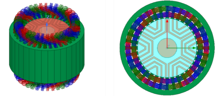
The 3D model of a 2.2kW 6-pole synchronous reluctance motor is presented in Figures 2 and 3.
Figure 2. 3D modeling of the SynRM
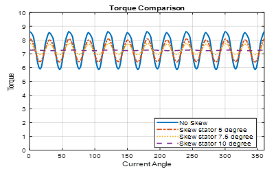
Figure 3. Electromagnetic torque waveforms versus current angle for the reference (skewless) design and stator slot skewing cases at 5°, 7.5°, and 10° mechanical skew angles
To validate the analytical torque ripple reduction model, two-dimensional and three-dimensional FEA was carried out on a 2.2 kW, 36-slot, 6-pole synchronous reluctance motor (SynRM). The main machine parameters are presented in Tables 2-4. The skewless (reference) design produces an average electromagnetic torque of 7.1 Nm with a high peak-to-peak torque ripple of approximately 30% under rated load. This significant torque ripple originates primarily from the interaction between stator slot harmonics and the discrete rotor flux-barrier structure, resulting in dominant 6th and 12th order torque harmonics (in electrical angle).
Both continuous stator slot skewing and discrete (step) rotor skewing were investigated to mitigate these spatial harmonics and suppress torque ripple while minimizing the penalty on average torque.
Table 2. Initial parameters of the SynRM
|
Parameter |
Value |
Unit |
|
Power |
2.2 |
kW |
|
Speed |
3000 |
r/min |
|
Pole number |
6 |
pole |
|
Terminal voltage |
400 |
V |
|
Efficiency |
78 |
% |
|
Power factor |
0.8 |
|
Table 3. Stator calculation results
|
Parameter |
Value |
Unit |
|
Inner diameter |
85 |
mm |
|
Outer diameter |
135 |
mm |
|
Motor length |
69 |
mm |
|
Number of slots |
36 |
slot |
|
Number of turns per coil per phase |
40 |
turn |
Table 4. Optimized rotor dimensions
|
Parameter |
Value |
Unit |
|
Outer diameter |
84 |
mm |
|
Shaft diameter |
24 |
mm |
|
Number of flux barriers |
3 |
|
3.1 Stator slot skewing
The stator slot skewing modifies the axial distribution of the stator slot permeance and MMF harmonics, functioning as a spatial harmonic filter that effectively attenuates slot-harmonic-induced torque pulsations. Continuous skewing was applied using mechanical skew angles of 5°, 7.5°, and 10° (corresponding approximately to 0.5, 0.75, and 1.0 stator slot pitch, respectively). The electromagnetic torque waveforms for the different stator skew configurations are compared in Figure 3.
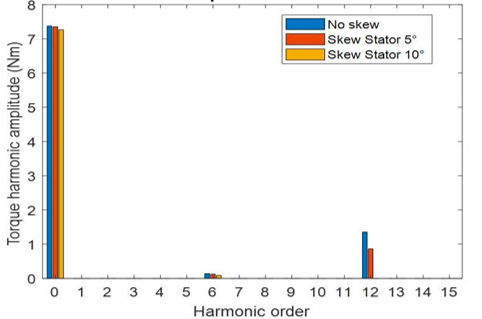
As shown in Figure 4, when no skew (reference case), the machine produces an average torque of approximately 7.1 Nm with a high peak-to-peak torque ripple of 30%. The torque waveform exhibits large oscillations caused by the strong interaction between stator slot harmonics and the rotor flux barriers, resulting in prominent 6th and 12th order torque harmonics. 5° mechanical skew: The average torque remains nearly unchanged at 7.1 Nm, while the torque ripple is reduced to 21.7%. The amplitude of the dominant harmonics begins to decrease, but significant ripple is still present. 7.5° mechanical skew: The average torque is 7.06 Nm, and the torque ripple drops further to 10.17%. A clear smoothing effect is observed in the torque waveform. 10° mechanical skew (optimal): The average torque is 6.9957 Nm (a reduction of less than 1.5% compared to the reference), while the torque ripple is dramatically reduced to approximately 2.2%. This represents a torque ripple reduction of more than 92% relative to the unskewed design. Increasing the stator skew angle progressively flattens the torque waveform. The 10° skew case produces the smoothest torque curve with minimal pulsation. Frequency domain (FFT) analysis confirms that the dominant 6th and 12th order torque harmonics are almost completely suppressed at this optimal skew angle. Higher-order harmonics are also significantly attenuated as the skew angle increases, which is consistent with the theoretical skew factor (inclination coefficient) for the ν-th harmonic in Eq. (16).
Figure 4. Harmonic spectra of the electromagnetic torque for different stator slot skew angles: No skew (reference case), 5° mechanical skew, and 10° mechanical skew
Figure 4 confirms that increasing the stator skew angle leads to progressive and remarkable attenuation of the dominant torque harmonics (especially 6th and 12th orders). The 10° mechanical skew provides near-optimal harmonic filtering, validating the effectiveness of stator slot skewing as a powerful technique for mitigating torque ripple in synchronous reluctance motors through axial phase shift of harmonic components.
The relationship between mechanical skew angle and the performance of average torque and ripple for stator slot skewing is illustrated in Figure 5. It is observed that increasing the skew angle has a negligible impact on average torque, causing only a slight reduction. In contrast, torque ripple significantly declines, reaching a nadir at a 10° mechanical skew angle. This specific angle represents the ideal balance, achieving the lowest ripple without sacrificing much torque. Mechanical skewing outperforms electrical skewing here because the primary torque ripple is tied to the stator slotting's mechanical pitch. Ultimately, for a 36-slot/6-pole SynRM, a 10° mechanical skew ensures peak efficiency with minimal torque loss.
Figure 5. Sensitivity analysis of average torque and torque ripple with respect to mechanical stator skew angle
3.2 Rotor slot skewing
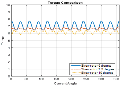
The simulation results demonstrate the trade-off between torque ripple reduction and average torque in a skewed rotor design. Increasing both the number of skew steps and the skew angle leads to a reduction in average torque and affects torque ripple.
For the rotor with n = 3 steps, the following results were obtained at different skew angles (skew factors determined to eliminate the fundamental harmonic while maintaining n = 3) configurations are compared in Figure 6.
Figure 6. Torque comparison for different rotor skew angles (n = 3 steps)
Figure 7 presents at the skew angle 5°: Average torque = 6.7 Nm, Torque ripple = 17%, at skew angle 7.5°, average torque = 6.4 Nm, Torque ripple = 3.9% and skew angle 10°, average torque = 5.97 Nm, torque ripple = 6.9%.
Figure 7. Torque comparison for different rotor skew angles (n = 5 steps)
The reduction in average torque with increasing skew angle is consistent with experimental observations. However, torque ripple remains slightly asymmetric, primarily due to uncompensated leakage flux components that persist under rotor skewing. This highlights the need for careful optimization of skew parameters in permanent magnet machine design to balance cogging torque, ripple, and output performance.
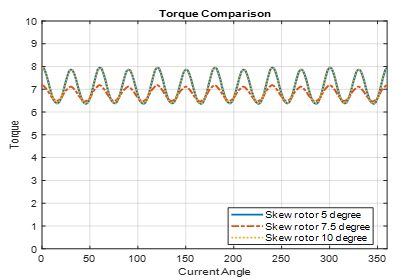
The simulation results illustrate the effectiveness of increasing the number of skew steps to n = 5. Figure 8 presents the torque comparison across different skew angles (5°, 7.5°, and 10°), showing a significant overall improvement in waveform smoothness compared to the n = 3 case.
Figure 8. Torque comparison for different rotor skew angles with fundamental harmonic elimination (n = 5 steps)
Figure 8 highlights the torque waveforms when the skew factors are specifically determined to eliminate the fundamental harmonic, providing a clearer view of ripple behavior under optimized skew conditions. Key results for n = 5 steps (fundamental harmonic elimination): Skew angle 5°: $k_{T_{\text {skew pole } R E}}=0,998$, Skew angle 7.5°: $k_{T_{\text {skew pole } R E}}=0,995$, Skew angle 10°: $k_{T_{\text {skew pole } R E}}=0,992$.
Increasing the number of skew steps to n = 5 substantially reduces torque ripple. Notably, at 10° skew, the torque ripple decreases significantly to only 3.2%, although average torque still experiences a moderate reduction due to the skew effect. This demonstrates that multi-step rotor skewing is a highly effective technique in design for achieving excellent torque ripple minimization while preserving acceptable average torque. The higher step count also results in more symmetric torque waveforms.
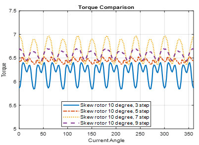
The results show that increasing the number of skew steps leads to a noticeable improvement in average torque. However, the torque ripple does not follow a clear monotonic trend and exhibits irregular behavior across different step counts. This indicates that while multi-step skewing generally enhances average torque output at fixed skew angle, the interaction between skew steps and remaining harmonics results in complex ripple characteristics that are difficult to predict intuitively.
Further detailed analysis using harmonic decomposition or parametric optimization via the finite element method (FEM) is recommended to fully understand and optimize the trade-off between average torque and torque ripple in multi-step skewed rotor designs.
Figure 9 presents the electromagnetic torque waveforms at a constant skew angle of 10° while varying the number of skew steps (3, 5, 7, and 9 steps).
Figure 9. Torque comparison at fixed 10° skew angle with varying number of skew steps
Figure 10 illustrates the variation of average torque and torque ripple as a function of mechanical skew angle from 5° to 20° with a fixed number of skew steps n = 3. The results confirm that average torque decreases gradually with increasing skew angle, consistent with the reduction in the fundamental skew factor. Meanwhile, torque ripple drops sharply and reaches its minimum at 10°, making this angle the optimal choice for rotor skewing under 3-step configuration. Beyond 10°, torque ripple increases slightly before decreasing again at higher angles. In general, for a low number of skew steps (n = 3), the mechanical skew angle should be selected at the minimum effective angle that sufficiently suppresses the dominant harmonics (in this case, 10°).
Figure 10. Average torque and torque ripple versus rotor skew angle (n = 3 steps)
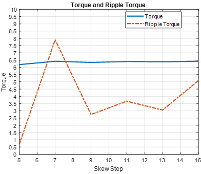
Figures 11 and 12 present the influence of the number of skew steps (from 5 to 15) on torque performance at a fixed mechanical skew angle of 10°. As shown in Figure 11, increasing the number of skew steps results in a reduction of average torque, which is consistent with the decrease in the skew factor according to the rotor skew theory. The minimum average torque occurs at 5 steps, where the torque ripple also reaches its lowest value. For skew steps greater than 9, the average torque becomes nearly stable, while the torque ripple remains well controlled at ≤5%.
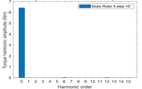
Figure 12 confirms that the 5-step skew configuration at 10° effectively eliminates the 6th and 12th order harmonics. This harmonic cancellation is the primary reason for the significant torque ripple reduction. The results demonstrate that simply increasing the number of skew steps without satisfying the harmonic elimination condition yields limited improvement. Optimal rotor skew design in SynRMs therefore requires careful selection of both the number of skew steps and the skew angle. In this study, the 5-step skew (with 2° per step) was selected as it simultaneously suppresses multiple dominant harmonics, particularly the 6th order. Consequently, the torque ripple was reduced by approximately 65% compared to the non-skewed case.
Figure 11. Average torque and torque ripple versus number of skew steps at fixed 10° skew angle
Figure 12. Harmonic spectrum of torque under 5-step skew
This paper has presented a rigorous comparative analysis of continuous stator slot skewing and discrete rotor step skewing techniques designed to mitigate torque ripple in a 2.2 kW, 36-slot/6-pole SynRM. The FEA results confirm that the 10° mechanical skew angle serves as the electromagnetic "sweet spot" for this specific slot-pole combination. Physically, a 10° mechanical angle perfectly matches one stator slot pitch, which directly introduces a 180° electrical phase shift between the dominant 6th and 12th order torque harmonics generated by the stator slotting and rotor flux-barrier interaction, thereby forcing their mathematical and physical cancellation upon axial superposition.
Continuous stator skewing achieved a remarkable 92% reduction in torque ripple (falling to 2.2%) with an insignificant average torque penalty (<1.5%), making it excellent for performance-critical drives. However, from an industrial manufacturing perspective, continuous lamination twisting increases stamping complexity and cost. On the other hand, the 5-step rotor skewing at the identical 10° angle provides a highly practical compromise, mitigating ripple by 65% while utilizing conventional straight-stator assembly lines. The study successfully demonstrates that shifting away from rigid empirical rules toward harmonic-targeted angle selection is vital for developing high-efficiency, low-noise, and cost-effective synchronous reluctance motors for industrial applications.
While the 2D and 3D FEA models implemented in this study utilize high-density meshes and non-linear \$B-H\$ curves to ensure high numerical fidelity, certain practical limitations must be acknowledged. This study relies entirely on electromagnetic simulations, which assume perfectly insulated lamination sheets and ideal geometric alignments. In real-world manufacturing, machining tolerances, laser-cutting stresses, and axial misalignments between skewed rotor steps can induce local magnetic saturation and unintended stray fields. Furthermore, step skewing creates discrete axial boundaries that can trigger localized step-edge flux leakage, a phenomenon that slightly compromises the ideal harmonic cancellation predicted by the theory. Due to institutional resource constraints, physical prototype fabrication and laboratory dyno bench tests were not executed for this revision. Future work will focus on fabricating a physical 2.2 kW SynRM prototype with a 5-step skewed rotor to experimentally validate the torque ripple suppression and evaluate the acoustic noise and vibration performance under dynamic drive conditions.
This research is funded by Hanoi University of Industry under project number 10-2024-RD/HD-ĐHCN.
[1] Heidari, H., Rassõlkin, A., Kallaste, A., Vaimann, T., Andriushchenko, E., Belahcen, A., Lukichev, D.V. (2021). A review of synchronous reluctance motor-drive advancements. Sustainability, 13(2): 729. https://doi.org/10.3390/su13020729
[2] Vagati, A., Canova, A., Chiampi, M., Pastorelli, M., Repetto, M. (2000). Design refinement of synchronous reluctance motors through finite-element analysis. IEEE Transactions on Industry Applications, 36(4): 1094-1102. https://doi.org/10.1109/28.855965
[3] Gallardo, C., Madariaga, C., Tapia, J.A., Degano, M. (2023). A method to determine the torque ripple harmonic reduction in skewed synchronous reluctance machines. Applied Sciences, 13(5): 2949. https://doi.org/10.3390/app13052949
[4] Shah, S.H., Mohammed, O.M.E., Rahman, S.U., Cai, H. (2025). Synchronous reluctance machine design considering slotting effect and rotor topology optimization. Engineering Science and Technology, an International Journal, 69: 102140. https://doi.org/10.1016/j.jestch.2025.102140
[5] Bomela, X., Kamper, M. (2002). Effect of stator chording and rotor skewing on performance of reluctance synchronous machine. IEEE Transactions on Industry Applications, 38(1): 91-100. https://doi.org/10.1109/28.980362
[6] Howard, E., Kamper, M.J., Gerber, S. (2015). Asymmetric flux barrier and skew design optimization of reluctance synchronous machines. IEEE Transactions on Industry Applications, 51(5): 3751-3760. https://doi.org/10.1109/tia.2015.2429649
[7] Korman, O., Di Nardo, M., Degano, M., Gerada, C. (2021). A novel flux barrier parametrization for synchronous reluctance machines. IEEE Transactions on Energy Conversion, 37(1): 675-684. https://doi.org/10.1109/tec.2021.3099628
[8] Hubert, T., Reinlein, M., Kremser, A., Herzog, H.G. (2015). Torque ripple minimization of reluctance synchronous machines by continuous and discrete rotor skewing. In 2015 5th International Electric Drives Production Conference (EDPC), Nuremberg, Germany, pp. 1-7. https://doi.org/10.1109/EDPC.2015.7323229
[9] Bianchi, N., Degano, M., Fornasiero, E. (2014). Sensitivity analysis of torque ripple reduction of synchronous reluctance and interior PM motors. IEEE Transactions on Industry Applications, 51(1): 187-195. https://doi.org/10.1109/tia.2014.2327143
[10] Minh, H.N.T., Nguyen, A.Q., Minh, T.P., Minh, D.B., Trong, C.T., Quoc, V.D. (2026). Effective analysis of permanent magnet positions on electromagnetic parameters of PMa-SynRMs. Journal Européen des Systèmes Automatisés, 59(2): 505-512. https://doi.org/10.18280/jesa.590219
[11] Guo, H., Wang, T., Chen, H., Song, Z., Liu, C. (2025). Design of a novel nine-phase ferrite-assisted synchronous reluctance machine with skewed stator slots. Energies, 18(9): 2323. https://doi.org/10.3390/en18092323
[12] Ban, B., Andersson, A., Stipetić, S. (2022). Design and torque ripple reduction methods for synchronous reluctance machine applied in electric power take-off actuation. In 2022 International Conference on Electrical Machines (ICEM), Valencia, Spain, pp. 476-482. https://doi.org/10.1109/ICEM51905.2022.9910674
[13] Bernard, N., Dang, L., Moreau, L., Bourguet, S. (2022). A pre-sizing method for salient pole synchronous reluctance machines with loss minimization control for a small urban electrical vehicle considering the driving cycle. Energies, 15(23): 9110. https://doi.org/10.3390/en15239110
[14] Chi, P.D., Huu, H.B., Quoc, V.D., Minh, D.B. (2025). Analytical and finite element methods for evaluative electromagnetic parameters of inset PMSM and SPMSM. Journal Européen des Systèmes Automatisés, 58(2): 337-343. https://doi.org/10.18280/jesa.580214
[15] Lazari, P. (2018). Permanent magnet assisted synchronous reluctance machines for electric vehicle traction applications, Ph.D. dissertation. University of Sheffield, Sheffield, U.K.
[16] Ying, H., Zhang, Z., Gong, J., Huang, S., Ding, X. (2010). Application for step-skewing of rotor of IPM motors used in EV. World Electric Vehicle Journal, 4(3): 532-536. https://doi.org/10.3390/wevj4030532
[17] Van, D.V., Nguyen, D.Q., Anh, T.P., Do, C.P., Duc, T. D., Chen, H., Quoc, V.D. (2026). Development of mesh-based generated reluctance network using trapezoidal elements based on lumped parameter model. Applied Computational Electromagnetics Society Journal (ACES), 376-388. https://doi.org/10.13052/2026.ACES.J.410410
[18] Pyrhönen, J., Jokinen, T., Hrabovcova, V. (2014). Design of Rotating Electrical Machines. 2nd ed. Chichester, U.K: Wiley.
[19] Duc, Q.N., Duy, T.N., Cong, T.T., Le Hai, N., Le Quy, D.D., Quoc, V.D., Minh, D.B. (2025). Electromagnetic parameters of IPM motors based on the genetic algorithm technique. Engineering, Technology & Applied Science Research, 15(3): 23855-23861. https://doi.org/10.48084/etasr.10559
[20] Huu, H.B., Thanh, B.D., Chuyen, T.D., Quoc, V.D. (2024). Design comparison of surface-mounted permanent magnet synchronous motors with inner and outer rotor configurations. International Journal of Power Electronics and Drive Systems (IJPEDS), 15(4): 2105-2114. https://doi.org/10.11591/ijpeds.v15.i4.pp2105-2114