Vivi Tri Widyaningrum* | Muhammad Fuad | Ahmad Sahru Romadhon | Ach. Dafid | Faikul Umam | Yuli Panca Asmara
© 2026 The authors. This article is published by IIETA and is licensed under the CC BY 4.0 license (http://creativecommons.org/licenses/by/4.0/).
OPEN ACCESS
Advances in vehicle technology demand control systems capable of adaptively enhancing safety and stability. One such approach is Adaptive Cruise Control (ACC), which serves to maintain speed while keeping a safe distance from objects ahead. This study aims to develop a real-time ACC system under sensor uncertainty using an Interval Type-2 Fuzzy Logic System (IT2FLS) implemented on a low-cost experimental vehicle platform. The methodology employed includes the design of an IT2FLS-based control system with two input variables—distance and speed—and its implementation on an experimental vehicle using an ESP32 microcontroller. The system utilizes an infrared (IR) distance sensor and an MPU6050 inertial sensor to capture vehicle motion conditions, while IT2FLS processes the uncertain sensor inputs through upper and lower membership functions, rule-based inference, type-reduction, and defuzzification to generate Pulse Width Modulation (PWM) control signals. Test results indicate that the IT2FLS system achieved an average travel time of 34 seconds on a 6-meter track, outperforming the manual test result of 44.6 seconds. The success rates for distance and acceleration readings reached 89.061% and 88.135%, respectively, with a smoother PWM modulation of 8.559. These findings show that IT2FLS can improve the stability of PWM modulation and vehicle response by reducing the effect of fluctuating sensor readings during real-time ACC operation. This study is aligned with the Sustainable Development Goals (SDGs) by supporting solutions to handle traffic congestion and to improve sustainable transportation and transportation (transport) technology through the development of safer, more adaptive, and more efficient vehicle control systems. However, the current evaluation is limited to a straight 6-meter track; therefore, further testing on curved roads, uneven terrain, dynamic acceleration–deceleration scenarios, and emergency braking conditions is required for broader real-world validation. The implications of this research are the potential for developing semi-autonomous vehicle systems that are more adaptive to dynamic environmental conditions.
Adaptive Cruise Control, Interval Type-2 Fuzzy Logic, sensor uncertainty, low-cost experimental vehicle, Pulse Width Modulation, traffic congestion, sustainable transportation, transportation (transport)
Automotive technology continues to evolve to enhance driving safety and comfort. Research on robot formation control has evolved from classical methods toward systems that are more intelligent, adaptive, and distributed [1]. One widely used technology is the Cruise Control System (CCS), which allows a vehicle to maintain a constant speed without driver intervention. CCS reduces driver workload and helps maintain a steady vehicle speed [2, 3].
Advancements in CCS have led to the development of a more adaptive system known as Adaptive Cruise Control (ACC). ACC not only maintains a constant speed but also adjusts the vehicle’s speed based on conditions ahead. ACC is capable of automatically slowing down or speeding up the vehicle [4, 5]. This system is designed to maintain a safe distance and reduce the risk of accidents. In practical driving conditions, ACC must respond to variations in vehicle speed, distance changes, road conditions, and sensor measurement uncertainty. Therefore, a control strategy that can maintain stable vehicle response under uncertain input conditions is required.
Although ACC has been widely adopted in modern vehicles, driving safety issues still frequently occur. Many accidents are caused by human error. Drivers often experience fatigue and lose focus [6]. This situation causes a delay in reacting to the vehicle ahead. The phenomenon of following too closely is one of the leading causes of accidents [7, 8]. Failure to maintain a safe distance increases the risk of rear-end collisions. This condition indicates that an ACC system should not only maintain speed but also provide an adaptive response to uncertain distance and motion information obtained from onboard sensors.
Various methods have been used to develop ACC systems. One of these is the Proportional-Integral-Derivative (PID) control method; however, this method has its limitations. Vehicle systems are nonlinear and dynamic, and changes in vehicle speed are not always predictable, making it difficult for PID to maintain stability under such conditions [9-11]. PID control generally depends on fixed control parameters, so its performance may decrease when the system is affected by nonlinear vehicle behavior, fluctuating sensor signals, and variations in operating conditions. These limitations motivate the use of intelligent control methods that are more flexible in handling uncertainty.
Another widely used method is fuzzy logic control. This method is capable of handling complex systems. Fuzzy Logic uses rules based on human language. This approach is more flexible than conventional methods [12, 13]. However, Type-1 Fuzzy Logic Systems have limitations. These systems are not yet capable of handling uncertainty optimally. Uncertainty arises from sensor noise and environmental conditions [14]. In Type-1 Fuzzy Logic, each input value is represented by a single membership degree. This representation can be insufficient when sensor readings fluctuate because of vibration, measurement noise, or environmental disturbance. As a result, the controller output may become less stable when the input data are uncertain.
Previous research has shown that fuzzy logic can improve the performance of an ACC. However, most studies still use Type-1 Fuzzy Logic. This approach is not robust enough to handle variations in real-world conditions. The Type-2 Fuzzy Logic System offers a better solution. This method is capable of handling uncertainty through the concept of the Footprint of Uncertainty (FOU) [15, 16]. In an Interval Type-2 Fuzzy Logic System (IT2FLS), uncertainty is represented by upper and lower membership functions, which form the FOU. This structure allows the controller to process uncertain sensor inputs within an interval rather than using only a single membership value. Therefore, IT2FLS is more suitable for ACC systems that rely on distance and motion sensors, where measurement noise can directly affect speed control decisions.
Recent studies have indicated that IT2FLS and related type-2 fuzzy approaches are increasingly used to improve robustness in nonlinear, uncertain, and dynamic systems, including mobile robots, robotic control systems, and intelligent vehicle-related applications [15, 16]. However, most existing studies emphasize simulation-based validation, complex control structures, or high-performance computational platforms. In contrast, real-time implementation of IT2FLS for ACC on a low-cost experimental vehicle using simple sensors and an embedded microcontroller remains limited. This gap is important because practical ACC development requires not only control accuracy but also real-time feasibility, sensor-noise tolerance, and low-cost implementation.
Based on these conditions, this study proposes an IT2FLS-based ACC system. The system is implemented on a vehicle platform. An infrared (IR) sensor is used to measure distance. An Inertial Measurement Unit (IMU) sensor is used to measure speed. The data is processed using an ESP32 microcontroller. As a result, the system can generate Pulse Width Modulation (PWM)-based control signals for vehicle speed regulation. The proposed system uses distance and speed information as IT2FLS inputs and produces PWM adjustment as the control output for vehicle motion regulation. Through the use of upper and lower membership functions, rule-based inference, type-reduction, and defuzzification, the controller is expected to generate smoother PWM changes under uncertain sensor readings.
In addition, this study is aligned with the Sustainable Development Goals (SDGs) by supporting solutions to handle traffic congestion and to improve sustainable transportation and transportation technology through the development of a safer, more adaptive, and more efficient vehicle control system. The main contribution of this study is the development of an IT2FLS-based ACC system on a simple platform. The system is designed to be low-cost yet adaptive. This study also evaluates the system’s performance experimentally. The evaluation focuses on speed stability, PWM modulation smoothness, and the ability to maintain a safe distance. The specific contributions of this study are summarized as follows: (1) developing a real-time IT2FLS-based ACC system on a low-cost experimental vehicle platform; (2) integrating an IR distance sensor, MPU6050 inertial sensor, ESP32 microcontroller, and PWM-based actuator control into a closed-loop ACC framework; (3) evaluating the ability of IT2FLS to reduce the effect of uncertain sensor readings on PWM modulation; and (4) experimentally comparing the proposed IT2FLS-based control response with manual operation on a straight test track.
2.1 Methodology and implementation
In this study, an ACC system was developed for an experimental vehicle and tested on a straight track. The system was designed to maintain the vehicle’s speed while automatically adjusting the safe distance to the object ahead. The controller was implemented using an IT2FLS, which processes inputs in the form of the distance to the vehicle ahead and the vehicle’s speed to generate a control signal in the form of PWM modulation. The entire data processing and control signal transmission process is performed in real-time via an ESP32 microcontroller connected to the system’s sensors and actuators.
2.2 Adaptive Cruise Control
ACC is a system or concept in the automotive industry, primarily used in cars, that maintains the vehicle’s speed at a level set by the driver. When there is a vehicle ahead traveling at a slower speed, this system adjusts the vehicle’s speed to match that of the vehicle in front [17, 18]. The following describes the operating principle of ACC, as shown in Figure 1.
Figure 1. How Adaptive Cruise Control (ACC) works [19]
The development of the ACC system is designed to reduce the burden on drivers who need to control the accelerator and brake pedals while steering the vehicle over long periods of time. The system uses data such as the distance ahead of the vehicle and the vehicle’s speed, as well as several additional sensors, to make decisions [20, 21]. The mathematical calculations in this system use standard methods, such as calculating the safe distance between vehicles, as shown in Eq. (1). To calculate the estimated time and distance between vehicles, Eqs. (2) and (3), and several other equations are used.
${{d}_{safe}}={{t}_{h}}{{v}_{f}}+{{d}_{0}}$ (1)
${{t}_{h}}={{t}_{0}}-{{c}_{v}}{{v}_{ref}}$ (2)
${{t}_{h}}={{t}_{0}}-{{c}_{v}}{{v}_{ref}}-{{c}_{a}}{{a}_{p}}$ (3)
2.3 Interval Type 2 Fuzzy Logic System
The IT2FLS is an extension of the Type-1 Fuzzy Logic System (T1FLS) designed to handle uncertainty in nonlinear and dynamic systems. In ACC systems, uncertainty arises due to sensor noise, variations in environmental conditions, and vehicle dynamics [22, 23]. Therefore, IT2FLS is used to improve the robustness of the control system. Unlike T1FLS, which assigns only one membership degree to each input value, IT2FLS represents the input using an interval of membership values. This interval-based representation enables the controller to tolerate fluctuations in sensor readings, such as distance variation from the IR sensor and acceleration noise from the MPU6050 sensor.
In an IT2FLS denoted by $\tilde{A},$ which has the membership function ${{\mu }_{{\tilde{A}}}}\left( x,u \right)$, where $x\in X~$and $u\in {{j}_{x}}\subseteq \left[ 0,1 \right]$ the type-2 fuzzy set can be written as shown in Eq. (4). Where if $0\le {{\mu }_{{\tilde{A}}}}\left( x,u \right)\le 1$, $\tilde{A}$ can be written as shown Eq. (5).
$\tilde{A}=\{\left( \left( x,u \right),{{\mu }_{{\tilde{A}}}}\left( x,u \right) \right)~|~\forall ~x\in X~~\forall ~u\in {{j}_{x}}\subseteq \left[ 0,1 \right]\}$ (4)
$\tilde{A}=\mathop{\int }_{x\epsilon X}^{~}\mathop{\int }_{u\epsilon {{j}_{x}}}^{~}\frac{{{\mu }_{{\tilde{A}}}}\left( x,u \right)}{\left( x,u \right)}~{{j}_{x}}\subseteq \left[ 0,1 \right]$ (5)
For every value of x = x’, in a two-dimensional plane where the axes are u and ${{\mu }_{{\tilde{A}}}}\left( x',u \right)$, the vertical slice is called the secondary membership function. A secondary membership function, which is a vertical section ${{\mu }_{{\tilde{A}}}}\left( x,u \right)$ is ${{\mu }_{{\tilde{A}}}}\left( x=x',u \right)$ for ${x}'\epsilon X$ and $\forall u~\epsilon {{j}_{{{x}'}}}~\subseteq \left[ 0,1 \right]$ can be written as shown in the Eq. (6).
${{\mu }_{{\tilde{A}}}}\left( x={x}',u \right)={{\mu }_{{\tilde{A}}}}\left( {{x}'} \right)=\mathop{\int }_{u\in {{j}_{x'}}}^{~}\frac{{{f}_{{{x}'}}}\left( u \right)}{\left( u \right)}~{{j}_{x'}}\subseteq \left[ 0,1 \right]$ (6)
The following is the IT2FLS membership function shown in Figure 2.
A secondary membership function interval reflects a uniform uncertainty in the primary membership of x. This is because all memberships in a type-1 set are unitary; consequently, a type-1 set is represented only by the domain of the interval, which is defined by the left and right endpoints [24]. In this study, the interval is used to represent uncertainty in the ACC input variables. For example, when the IR sensor reads a distance value, the actual value may fluctuate because of vibration, surface irregularity, or electrical interference. Therefore, IT2FLS does not process the sensor value as a single crisp membership degree, but as a bounded uncertainty region. The following is the IT2FLS block diagram shown in Figure 3.
Figure 2. Membership features Interval Type-2 Fuzzy Logic System (IT2FLS)
Figure 3. Diagram block Interval Type-2 Fuzzy Logic System (IT2FLS)
These two endpoints are associated with two types of membership functions, represented as the upper and lower membership functions, which are bounded by the footprint of uncertainties (FOU). The upper membership function (UMF) is associated with the boundary at the top of the FOU (Ã) and is denoted by ${{\bar{\mu }}_{{\tilde{A}}}}\left( x \right),\forall x\in X$. Where the Lower membership function (LMF) is associated with the bottom boundary of the FOU ($\tilde{A})$ and is represented by ${{\underset{\scriptscriptstyle-}{\mu }}_{{\tilde{A}}}}\left( x \right),\forall x\in X$. The area between the UMF and LMF is called the Footprint of Uncertainty. In the proposed ACC system, the FOU provides a tolerance region for uncertain sensor inputs before the control decision is converted into PWM modulation. This mechanism is expected to reduce abrupt PWM changes caused by sudden sensor fluctuations.
This IT2FLS control system uses shoulder curves and triangular curves. It has two inputs: data from the IR sensor and the MPU6050 sensor, which have linguistic values (UMF and LMF). The IR sensor and the MPU6050 sensor have different membership functions because the vehicle’s distance and speed vary [15]. The Fuzzy Inference System (FIS) model used is the Multiple-Input Single-Output (MISO) model, which uses readings from the IR sensor and the MPU6050 sensor as inputs. These inputs are processed using a rule editor, which then generates an output in the form of a PWM adjustment (defuzzification), as shown in Figure 4. In this stage, the distance input represents the spacing between the experimental vehicle and the object ahead, while the speed input represents the vehicle motion condition derived from the inertial sensor. Both inputs are fuzzified into linguistic variables using UMF and LMF to preserve uncertainty information before entering the inference stage.
Figure 4. Model FIS Multiple-Input Single-Output (MISO)
The following are the membership sets of the variables IT2FLS, speed, and distance, which are the system inputs, namely:
The velocity membership function (ve) is an input signal consisting of five sets: “Very Slow (SL)” (≤21 cm/s & ≤19 cm/s), “Slow (L)” (9–31 cm/s & 11–29 cm/s), “Normal (N)” (19–41 cm/s and 21–39 cm/s), “Fast (C)” (29–51 cm/s and 31–49 cm/s), and “Very Fast (SC)” (≥39 cm/s and ≥41 cm/s). The following are the membership degrees of the IT2FLS velocity variable, which consists of 5 sets, as shown in Figure 5. The use of two boundary values in each linguistic set indicates that the speed input is not treated as a fixed value, but as an uncertain interval. This is important because acceleration and velocity estimation from the MPU6050 may be affected by vibration and sensor drift.
Figure 5. Degree of freedom of the velocity variable
The distance membership function (d) is an input signal consisting of five sets: “Very Close (SD)” (≤ 38 cm & ≤ 42 cm), “Close (D)” (18–62 cm & 22–58 cm), “Normal (N)” (38–82 cm & 42–78 cm), “Far (F)” (58–102 cm & 62–98 cm), and “Very Safe (VS)” (≤ 78 cm & ≤ 82 cm). Figure 6 shows the membership degrees of the distance variable IT2FLS, which consists of 5 sets, as shown in Figure 6. The interval distance membership function enables the controller to handle uncertainty in the IR sensor reading. Thus, when the measured distance fluctuates near the boundary between two linguistic categories, the IT2FLS can still produce a gradual control response instead of an abrupt decision.
Figure 6. Degree of membership of the distance variable
The PWM (defuzzy) control uses membership degrees divided into four categories: “high acceleration (PCB)” (20), “acceleration (PC)” (10), “deceleration (PB)” (-10), and “high deceleration (PBB)” (-20). The PWM change is used as the control output to regulate motor speed. Positive values increase the PWM signal for acceleration, whereas negative values reduce the PWM signal for deceleration. Therefore, the fuzzy output directly determines how the vehicle responds to distance and speed variations.
After performing fuzzification by defining membership functions, a rule base was constructed using the basic rule IF x is A AND IF y is B THEN z is C, which is divided into upper and lower sets. The following is the rule base of the IT2FL system, as shown in Table 1. The rule base connects the distance and speed conditions with the required PWM adjustment. For example, when the vehicle is too close to the object ahead and its speed is high, the controller produces a deceleration output. Conversely, when the distance is safe and the vehicle speed is low, the controller can generate an acceleration output. This rule mechanism links the IT2FLS architecture directly to the ACC objective, namely maintaining a safe distance and stable speed.
Table 1. Table of rule base
|
$d/ve$ |
SL |
L |
S |
C |
SC |
|
SJ |
PCB |
PCB |
PCB |
PC |
PB |
|
J |
PCB |
PCB |
PC |
PB |
PB |
|
N |
PCB |
PC |
PB |
PB |
PBB |
|
D |
PC |
PB |
PB |
PBB |
PBB |
|
SD |
PB |
PB |
PBB |
PBB |
PBB |
The following are the variable descriptions from Table 1:
SL: Membership degree “Very Slow”
L: Membership degree “Slow”
S: Membership degree “Standard”
C: Membership degree “Fast”
S: Membership degree “Very Fast”
SJ: Membership degree “Very Far”
D: Membership degree “Far”
N: Membership degree “Normal”
D: Membership degree “Near”
SD: Membership degree “Very Near”
PCB: Membership degree “High Acceleration”
PC: Membership degree “Acceleration”
PB: Membership degree “Deceleration”
PBB: Membership degree “High Deceleration”
To avoid ambiguity in the rule notation, the distance linguistic labels should be consistently written as Very Far, Far, Normal, Near, and Very Near, while the speed linguistic labels should be written as Very Slow, Slow, Standard, Fast, and Very Fast. This consistency helps clarify the relationship between input conditions and PWM output decisions.
Type reduction is a process step for reducing the IT2FLS set to a Type 1 fuzzy set. In this process, the reduction method used is the center-of-set method, as described in Eqs. (7) and (8) [25]. The type-reduction stage combines the firing strengths obtained from the UMF and LMF to produce an output interval. This interval represents the possible range of control actions under uncertain input conditions.
$y\left( {{\theta }_{1}},\ldots ,~{{\theta }_{Z}} \right)=\frac{\mathop{\sum }_{z=1}^{Z}{{y}_{z}}{{\theta }_{z}}}{\mathop{\sum }_{z=1}^{Z}{{\theta }_{z}}}$ (7)
${{y}_{lk}}=\frac{\mathop{\sum }_{i=1}^{M}f_{l}^{i}y_{lk}^{i}}{\mathop{\sum }_{i=1}^{M}f_{l}^{i}}$ (8)
In the type-reduction stage, the output of each type-reduced set is determined by the leftmost point ${{y}_{lk}}$and the rightmost point ${{y}_{rk}}$. The set interval is defuzzified using the average of ${{y}_{lk}}$ and ${{y}_{rk}}$; therefore, the defuzzified crisp output for each output k can be written as in Eq. (9).
${{y}_{k}}\left( x \right)=\frac{{{y}_{lk}}+{{y}_{rk}}}{2}$ (9)
In the developed system, IT2FLS receives two main inputs: the distance between the vehicle and the object ahead (d) and the vehicle’s speed (v). The output, which is the change in PWM (ΔPWM), is used to control the vehicle’s acceleration or deceleration [26]. The final crisp output is then sent to the ESP32 as a PWM adjustment command for the motor driver. Consequently, the complete IT2FLS process can be summarized as follows: uncertain distance and speed inputs are fuzzified using UMF and LMF, processed through the rule base, reduced into an output interval, defuzzified into a crisp ΔPWM value, and applied to regulate vehicle motion in real time. This sequence explains how the IT2FLS block contributes to smoother PWM modulation and more adaptive ACC behavior in the experimental results.
2.4 Ackermann steering
When turning a vehicle, if the centers of all the wheels coincide at a single point, the vehicle will turn around that point, resulting in pure rolling motion. This condition is known as the Ackermann condition, and this principle is known as the Ackermann principle. Figure 7 illustrates the kinematics of Ackermann steering.
Figure 7. Ackermann steering kinematics [27]
Ackermann steering geometry is most commonly used in commercial vehicles. The purpose of Ackermann steering is to prevent the tires from sliding sideways when following a curved road and to improve maneuverability at low speeds [28]. The following are the equations used in Ackermann steering kinematics:
1. The Ackermann angle in Eq. (10).
$\propto =ta{{n}^{-1}}\left( \frac{\frac{c}{2}}{b} \right)$ (10)
2. Inner wheel lock-up angle in Eq. (11).
$sin\theta =b-\frac{a-c}{2}$ (11)
3. The locking angle of the outer wheel in Eq. (12).
$cot\varphi -cot\theta =\frac{c}{b}$ (12)
4. Inner front wheel turning radius in Eq. (13).
${{T}_{IF}}=\frac{b}{sin\theta }-\frac{a-c}{2}$ (13)
5. The turning radius of the outer front wheel in Eq. (14).
${{T}_{OF}}=\frac{b}{sin\theta }-\frac{a-c}{2}$ (14)
6. The average turning radius in Eq. (15).
${{T}_{R}}=\frac{{{T}_{IF}}-{{T}_{OF}}}{2}$ (15)
7. The value of Ackermann in Eq. (16).
$nilai~ackermann=ta{{n}^{-1}}\left( \frac{b}{\frac{b}{tan\theta }-a} \right)$ (16)
8. Ackermann % in Eq. (17).
$ackerman\%=\frac{\theta}{\text { value of ackermann }} \times 100$ (17)
where,
$a$ = wheel track, or the distance between the left and right wheels
b = wheelbase or the distance between the front and rear wheels
c = distance between pivot
$\theta $ = inner wheel lock angle
$\varphi $ = outer wheel lock angle
${{T}_{IF}}$ = inner front wheel turning radius
${{T}_{OF}}$ = outer front wheel turning radius
${{T}_{R}}\text{ }\!\!~\!\!\text{ }$= average turning radius
In the ACC system, Ackermann steering kinematics are applied in the design of the vehicle's steering kinematics to make the vehicle's steering system as similar as possible to that of a real car and to ensure good stability while the vehicle is in motion.
2.5 Device design
The experimental vehicle system adopts Ackermann steering kinematics, with the two rear wheels as the drive wheels and the two front wheels controlled by a servo motor. Rear drive motors are mounted to maintain center-of-gravity balance and stable propulsion.
The vehicle has a two-layer structure: the first layer houses mechanical components and the IR sensor, while the second layer houses electronic components such as the ESP32, MPU6050, and servo motor. The acrylic frame (3 mm thick, 400 × 200 mm) provides structural support and stability for the steering system.
Figure 8 shows the mechanical layer (Layer 1) with key components:
Figure 9 shows the electronic layer (Layer 2) with:
Figure 8. Design system vehicle layer 1
Figure 9. Design system vehicle layer 2
Functional Integration with IT2FLS:
This design emphasizes functional integration rather than detailed mechanical layout, showing how each component contributes to real-time IT2FLS-based ACC performance.
2.6 Electronic circuit
To achieve good movement and control of the vehicle, a properly designed electronic circuit is required. This electronic circuit is designed to process sensor readings, control the drive motors, and control the steering servo motor. The following is the electronic circuit for the vehicle shown in Figure 10.
Figure 10. Electronic circuit
2.7 Block diagram system
The system block diagram illustrates the workflow of each component in the vehicle as a closed-loop control system, ensuring that the process operates in a repetitive and continuous manner. As shown in Figure 11, the system begins by measuring the distance to the vehicle ahead and the ego vehicle’s speed; this data is then processed in the fuzzy logic block to determine the required speed limits and deceleration. Next, the IT2FLS output is processed by the microcontroller into a control signal that is transmitted to the motor driver to drive the motor.
Figure 11. Adaptive Cruise Control (ACC) block diagram for the vehicle
Figure 11 identifies several variables that influence the process; the following is an explanation of those variables:
2.8 Flowchart system
Figure 12 shows the flowchart of the main vehicle system. First, the input values from the IR sensor and MPU6050 are read. Then, the system checks whether the driver has pressed the switch to activate the system. If the switch is activated, the Adaptive Cruise Control System (ACCS) will engage, and the functions of the accelerator and brake pedals will correspond to the switch settings. To deactivate the system and return to manual drive mode, the driver must press the switch. If the switch is turned off, the system immediately enters manual drive mode. In the ACCS sub-process flowchart, the system begins by reading the vehicle’s speed and distance variables, followed by the IT2FLS method sub-flowchart and the ACC sub-flowchart, as shown in Figure 13.
Figure 12. Main flowchart system
Figure 13. Sub-flowchart Adaptive Cruise Control System (ACCS)
In the IT2FLS method sub-flowchart, the process begins by reading inputs from the IR sensor and the MPU6050 sensor, then proceeds through several steps as shown in Figure 14, resulting in an output variable representing the (defuzzied) PWM change.
Sub-flowchart The IT2FLS method sub-flowchart generates the required (defuzzified) PWM change output variable. This defuzzified variable serves as an input to the ACC sub-flowchart. It then becomes one of the inputs in the ACC sub-flowchart, as shown in Figure 15.
Figure 14. Sub-flowchart Interval Type-2 Fuzzy Logic System (IT2FLS)
Figure 15. Sub-flowchart Adaptive Cruise Control (ACC)
Figures 12 through 15 identify several variables that influence the process; the following is an explanation of those variables:
3.1 Testing and calibration sensor
There are several sensors used in the vehicle system, namely IR sensors and accelerometers. To ensure the vehicle system responds appropriately, accurate sensor readings are required. Therefore, the sensors must first be tested and calibrated to ensure their readings meet the desired specifications. These calibrated sensor values serve as inputs to the IT2FLS module, which generates PWM signals for real-time vehicle control.
3.1.1 Testing and calibration infrared sensor
During the IR sensor calibration, data samples were collected for 1 minute with an actual distance of 50 cm between the vehicle system and the obstacle in front of it. The data samples obtained from the IR sensor calibration are shown in Figure 16. The filtered distance readings are then normalized and fed into the IT2FLS controller as one of the input variables for PWM generation.
Figure 16. Sample graph of infrared (IR) sensor reading data
3.1.2 Testing and calibration MPU6050 sensor
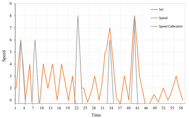
Testing and calibration of the MPU6050 sensor were performed for 1 minute with the vehicle system at rest, assuming an acceleration of 0 cm/s². Additionally, if the sensor reading was between 0 and 5 cm/s², it was set to 0 cm/s² to stabilize the system. From the calibration of the MPU6050 sensor, several data samples were obtained, as shown in Figure 17. These acceleration readings are processed and used as the second input variable for IT2FLS to determine PWM adjustments for motor speed control.
Figure 17. Sample data from the MPU6050 sensor
3.2 Communication testing
A third-party application is required to connect the vehicle system with users and store data. In this study, the Firebase website was used to connect the vehicle system with users and store data. Table 2 presents the results of the communication testing between the vehicle system and the Firebase website. Stable and timely communication is critical for real-time ACC performance. Any delays or interruptions in data transmission may lead to transient fluctuations in PWM signals, which can affect the vehicle’s speed and distance control. The testing ensured that communication latency remained within acceptable limits to maintain accurate IT2FLS operation.
Table 2. Sample data communication
|
No. |
Distance (m) |
Communication Status |
Time (s) |
|
1 |
2 |
Connected |
9.44 |
|
2 |
4 |
Connected |
9.54 |
|
3 |
6 |
Connected |
6.35 |
|
4 |
8 |
Connected |
8.51 |
|
Average Connection Time |
8.46 |
||
3.3 Manual testing
Vehicle system testing was conducted on a 6-meter-long straight track with a paved surface. In this test, the object was placed 2 meters in front of the vehicle system and moved simultaneously. From these tests, several variables were obtained, such as the average percentage error (re%), average speed, average PWM, and average PWM change. The tests were performed five times without using IT2FLS to control the vehicle system’s speed, as shown in Figures 18-22. Figures 18-22 illustrate that PWM signals in manual testing were directly controlled by the user, resulting in more abrupt changes and higher fluctuations compared to automated control.
From manual test 1 through manual test 5, the average success rates for distance and acceleration readings were 87.934% and 81.664%, respectively, excluding data affected by communication errors in test 4, with an average elapsed time of 44.6 seconds, an average PWM of 37.226, and an average PWM change of 10. The higher PWM change indicates manual operation is more prone to sudden adjustments, and the variability in distance and acceleration measurements reflects human reaction limitations. Several errors occurred in the readings due to a drop in power supply, internet connection issues, and most of these errors were caused by uneven terrain around the 3m and 4m points. These observations demonstrate the need for automated IT2FLS control to stabilize vehicle response and reduce abrupt PWM changes.
Figure 18. Graph of manual test results 1
Figure 19. Graph of manual test results 2
Figure 20. Graph of manual test results 3
Figure 21. Graph of manual test results 4
Figure 22. Graph of manual test results 5
3.4 Testing IT2FL
Vehicle system testing was conducted on a 6-meter-long straight track with a paved surface. In this test, the object was placed 2 meters in front of the vehicle system and moved simultaneously. From these tests, several variables were obtained, such as the average percentage error (re%), average speed, average PWM, and average PWM change. The tests were performed five times using IT2FL to control the vehicle system’s speed, as shown in Figures 23-27.
Figure 23. Graph of test result data with IT2FL 1
Figure 24. Graph of test result data with IT2FL 2
Figure 25. Graph of test result data with IT2FL 3
Figure 26. Graph of test result data with IT2FL 4
From the tests with IT2FL 1 through the tests with IT2FL 5, the average success rates for distance and acceleration readings were 89.061% and 88. 135%, with interference caused by uneven paths and electromagnetic field interference from other components amounting to 10.939% and 11.865%, respectively, with an average travel time of 34 seconds, an average PWM of 47, and an average PWM change by the system of 8.559. Unlike in manual testing, distance and acceleration readings are crucial components of testing with IT2FL to obtain PWM changes that are entirely generated by the system.
Figure 27. Graph of test result data with IT2FL 5
Unlike manual testing, the PWM signals in IT2FLS testing were generated entirely by the system, resulting in smoother speed control and more stable distance and acceleration readings. The IT2FLS block processed the fuzzified IR and MPU6050 inputs, performed inference, type-reduction, and defuzzification, and produced PWM outputs that adaptively regulated the motors in real time.
Despite improvements, the testing environment was limited to a straight track and controlled indoor conditions. Future work should include curved tracks, uneven terrain, dynamic acceleration/deceleration scenarios, and emergency braking to evaluate IT2FLS performance under more realistic driving conditions.
This study demonstrates that the application of the IT2FLS in an ACC system is capable of improving control performance compared to manual testing. On a 6-meter track, the IT2FLS-based system achieved an average travel time of 34 seconds, which is shorter than the 44.6 seconds recorded in manual testing. In terms of sensor readings, the IT2FLS method also provided better results, with a distance reading success rate of 89.061% and an acceleration success rate of 88.135%, whereas manual testing only achieved 87.934% for distance readings and 81.664% for acceleration. Additionally, the average PWM change in the IT2FLS system was 8.559, which is smaller than the 10 recorded in the manual test, indicating that the system is capable of producing a smoother and more adaptive control response. These results confirm that the IT2FLS block effectively converts uncertain sensor inputs into stable PWM outputs, providing adaptive real-time control that maintains vehicle speed and safe distance.
Nevertheless, the system’s performance is still influenced by the quality of sensor readings. Disturbances such as noise caused by track irregularities and electromagnetic interference from other components can result in PWM outputs that do not always match the expected values. Moreover, the experiments were limited to straight tracks, so performance under curved paths or dynamic acceleration/deceleration scenarios was not evaluated.
For future research, the system can be further developed by integrating more stable sensors, enhancing data communication reliability, implementing braking mechanisms, and testing on more complex track conditions including curves and uneven terrain. These improvements will allow IT2FLS-based ACC to be validated under realistic dynamic driving scenarios.
The authors would like to express their sincere gratitude and acknowledgment the institute for Research and Community Service (Lembaga Penelitian dan Pengabdian Masyarakat, LPPM) at The University of Trunodjoyo Madura (UTM) for their generous funding provided towards our independent research under Grup Riset scheme in 2023 (contract number 5844/UN46.4.1/PT.01.03/2023). The authors also would like to thank INTI International University, Malaysia for the collaboration that has been established.
[1] Xu, Y., Batumalay, M., Chan, C.K., Wider, W., Fu, K., Yang, L., Peng, J. (2025). Hot topics and frontier evolution of formation control research in multiple robots. Journal of Robotics, 18. https://doi.org/10.1155/joro/3827954
[2] Liu, L., Zhang, Q., Liu, R., Zhu, X.C., Ma, Z.X. (2021). Adaptive cruise control system evaluation according to human driving behavior characteristics. Actuators, 10(5): 90. https://doi.org/10.3390/act10050090
[3] Bellamri, I., Moreau, X., Benine Neto, A., Haj Frej, G.B., Aioun, F. (2025). Crone cruise control system for electric vehicle. IFAC-PapersOnLine, 59(37): 181-186. https://doi.org/10.1016/j.ifacol.2026.01.031
[4] Pan, C.F., Zhang, C., Wang, J., Liu, Q. (2023). Adaptive cruise control strategy for electric vehicles considering battery degradation characteristics. Applied Sciences, 13(7): 4553. https://doi.org/10.3390/app13074553
[5] Bai, J., Lee, J., Mao, S. (2024). Effects of adaptive cruise control system on traffic flow and safety considering various combinations of front truck and rear passenger car situations. Transportation Research Record: Journal of the Transportation Research Board, 2678(8): 1009-1028. https://doi.org/10.1177/03611981231223982
[6] Zhang, H., Ni, D.A., Ding, N.K., Sun, Y.F., Zhang, Q., Li, X. (2023). Structural analysis of driver fatigue behavior: A systematic review. Transportation Research Interdisciplinary Perspectives, 21: 100865. https://doi.org/10.1016/j.trip.2023.100865
[7] Sheikh, M.S., Peng, Y.Q. (2025). Assessment of rear-end collision risk based on a deep reinforcement learning technique: A break reaction assessment approach. IEEE Access, 13: 20171-20190. https://doi.org/10.1109/ACCESS.2025.3534787
[8] Li, T., Chen, D.J., Zhou, H., Laval, J., Xie, Y.C. (2021). Car-following behavior characteristics of adaptive cruise control vehicles based on empirical experiments. Transportation Research Part B: Methodological, 147: 67-91. https://doi.org/10.1016/j.trb.2021.03.003
[9] Nazir, K., Kim, Y.W., Byun, Y.C. (2025). Predictive PID control for automated guided vehicles using genetic algorithm and machine learning. IEEE Access, 13: 66726-66741. https://doi.org/10.1109/ACCESS.2025.3559072
[10] Wang, Y.Q., Hou, W.J., Liang, L. (2025). Prescribed performance optimal fault-tolerant control for nonlinear systems with mismatched disturbances via zero-sum differential game. ISA Transactions, 164: 91-99. https://doi.org/10.1016/j.isatra.2025.05.026
[11] Fuad, M., Wahyuni, S., Bayuaji, L., Asmara, Y.P., Rachmad, A. (2026). Drone control using upper body gesture based on pose detection and random forest for monitoring in smart agriculture. Journal Européen des Systèmes Automatisés, 59(1): 133-144. https://doi.org/10.18280/jesa.590113
[12] Sun, J., Ma, K.X., Feng, Y. (2025). A dynamic interval Type-2 fuzzy stochastic configuration network for nonlinear system modeling. IEEE Transactions on Fuzzy Systems, 33(10): 3609-3623. https://doi.org/10.1109/TFUZZ.2025.3596702
[13] Dumitrescu, C., Ciotirnae, P., Vizitiu, C. (2021). Fuzzy logic for intelligent control system using soft computing applications. Sensors, 21(8): 2617. https://doi.org/10.3390/s21082617
[14] Zou, M.Y., Yi, J., Yang, C.H., Liao, Q., Xiong, W., Wang, X.L. (2022). Adaptive fuzzy logic control for grinding process based on grinding sound trend. IFAC-PapersOnLine, 55(21): 120-125. https://doi.org/10.1016/j.ifacol.2022.09.254
[15] Nguyen, V.T., Giap, H.B., Mai, T.V., Hoang, T.D., Phan, X.T. (2025). Type 2 fuzzy consensus control for leader-follower multiple Euler-Lagrange system under faults and deception attack. IEEE Access, 13: 158170-158182. https://doi.org/10.1109/ACCESS.2025.3606250
[16] Al-Mahturi, A., Santoso, F., Garratt, M.A., Anavatti, S.G. (2023). A novel evolving Type-2 fuzzy system for controlling a mobile robot under large uncertainties. Robotics, 12(2): 40. https://doi.org/10.3390/robotics12020040
[17] Maruyama, N., Mouri, H. (2022). A proposal for adaptive cruise control balancing followability and comfortability through reinforcement learning. ROBOMECH Journal, 9: 22. https://doi.org/10.1186/s40648-022-00235-7
[18] Choi, K.H., Chang, H.J. (2025). Improvement of adaptive cruise control system performance on sloped roads based on adaptive neuro-fuzzy inference system. IEEE Access, 13: 60519-60531. https://doi.org/10.1109/ACCESS.2025.3557089
[19] Kamal, M.A.S., Hashikura, K., Hayakawa, T., Yamada, K., Imura, J. (2022). Adaptive cruise control with look-ahead anticipation for driving on freeways. Applied Sciences, 12(2): 929. https://doi.org/10.3390/app12020929
[20] Lantieri, C., Acerra, E.M., Pazzini, M., Simone, A., Di Flumeri, G., Borghini, G. (2024). The impact of adaptive cruise control on the drivers’ workload and attention. IEEE Access, 12: 158824-158836. https://doi.org/10.1109/ACCESS.2024.3481654
[21] Liu, H., Guo, C.S., Han, L.J., Nie, S.D. (2025). Vehicle adaptive cruise control strategy based on improved safe distance model for off-roads with changeable pavement and slope. Proceedings of the Institution of Mechanical Engineers, Part D: Journal of Automobile Engineering, 239(9): 4172-4186. https://doi.org/10.1177/09544070241264881
[22] Yan, W., Tu, H.Y., Qin, P., Zhao, T. (2023). Interval Type-II fuzzy fault-tolerant control for constrained uncertain 2-DOF robotic multi-agent systems with active fault detection. Sensors, 23(10): 4836. https://doi.org/10.3390/s23104836
[23] Liu, S.C., Cai, R. (2021). Uncertainty of interval Type-2 fuzzy sets based on fuzzy belief entropy. Entropy, 23(10): 1265. https://doi.org/10.3390/e23101265
[24] Chu, Y., Han, H., Ma, T., Zhu, M., Li, Z., Xu, Z., Wu, Q. (2023). Interval Type-2 fuzzy PID controller using disassembled gradational optimization. Sensors, 23(22): 9067. https://doi.org/10.3390/s23229067
[25] Kelekci, E., Yaren, T., Kizir, S. (2022). Design of optimized interval type-2 fuzzy logic controller based on the continuity, monotonicity, and smoothness properties for a cart-pole inverted pendulum system. Transactions of the Institute of Measurement and Control, 44(12): 2291-2307. https://doi.org/10.1177/01423312221081309
[26] Atacak, İ., Çıtlak, O., Doğru, İ.A. (2023). Application of interval type-2 fuzzy logic and type-1 fuzzy logic-based approaches to social networks for spam detection with combined feature capabilities. PeerJ Computer Science, 9: e1316. https://doi.org/10.7717/peerj-cs.1316
[27] Kang, Y.H., Pang, D.C., Zeng, Y.C. (2025). Optimal dimensional synthesis of Ackermann steering mechanisms for three-axle, six-wheeled vehicles. Applied Sciences, 15(2): 800. https://doi.org/10.3390/app15020800
[28] Umam, F., Dafid, A., Asmara, Y.P., Budiarto, H., Sukri, H., Maolana, F. (2026). Vision-based steering control of an Ackermann mobile robot on curved roads using model predictive control. Journal Européen des Systèmes Automatisés, 59(1): 219-231. https://doi.org/10.18280/jesa.590120