The Nhat Nguyen![]() | Anh Tuan Do*
| Anh Tuan Do*![]() | Nhu Y Do
| Nhu Y Do![]() | Anh Tuan Le
| Anh Tuan Le![]()
© 2026 The authors. This article is published by IIETA and is licensed under the CC BY 4.0 license (http://creativecommons.org/licenses/by/4.0/).
OPEN ACCESS
Line-start permanent magnet synchronous motors (LSPMSMs) offer high efficiency and direct self-starting capability; however, their synchronization process strongly depends on load torque. This paper investigates the synchronization capability of a 2.2 kW, 1500 rpm LSPMSM under different load factors during direct-on-line startup and postsynchronization load increase. The results show that, during startup, the motor can synchronize at rated load but fails at a load factor of 1.07. During post-synchronization operation, stable synchronization is maintained up to a load factor of 1.79 , whereas the case of 1.86 represents the loss-of-synchronism boundary. For reliable operation, a conservative short-term overload limit of 1.6 times the rated load is recommended. When additional load is applied during steady operation, the maximum speed deviation follows the empirical relationship $\Delta n \approx 6,85 \Delta M_t$ within the stable load-increase range, which can support slip protection or speed-drop control. The power factor and efficiency also vary significantly with load factor. In the startup condition, efficiency reaches 95.9% at medium load, while the power factor increases toward approximately 0.90 near rated load. The results indicate that startup load should be limited below 0.95 of the rated load, and postsynchronization overload should be limited to about 1.6 times the rated load for stable and efficient operation.
line-start permanent magnet synchronous motors, electrical motor, load factor, MATLAB/Simulink, synchronous, starting
The three-phase squirrel-cage induction motor (IM) currently dominates industrial applications due to its simple structure, high starting torque, durability, and low cost. However, its main drawbacks include relatively low efficiency and power factor. In contrast, permanent magnet synchronous motors (PMSMs) offer significantly higher efficiency, but conventional PMSMs lack direct self-starting capability and require power converters for operation and control [1, 2].
To overcome these limitations, the line-start permanent magnet synchronous motor (LSPMSM) has been developed, combining the advantages of both IM and PMSM—namely, direct self-starting from the grid and high operational efficiency with high power density. The rotor of an LSPMSM integrates both permanent magnets and squirrel-cage bars, allowing the motor to start in asynchronous mode and transition to synchronous operation once nominal speed is reached, thereby eliminating rotor copper losses [3].
However, the most critical challenge for LSPMSMs lies in the startup and synchronization phases. The presence of permanent magnets introduces a braking torque during acceleration, which often reduces the overall starting torque. This makes it difficult for the motor to bring heavy or high-inertia loads up to synchronous speed. The motor’s ability to synchronize strongly depends on the magnitude and nature of the load torque; if the load or its inertia exceeds the allowable threshold, the motor may fail to synchronize, resulting in shutdowns or severe speed oscillations [4].
A finite element method was used to investigate the synchronization process during the startup of a 160 kW, 1500 rpm LSPMSM [5]. The results indicated the influence of the starting torque generated by the squirrel-cage bars as well as the excitation torque produced by the permanent magnets in the LSPMSM. An instantaneous state analysis of a direct LSPMSM was conducted, and an optimal design was developed to achieve high IE4 efficiency by using finite element analysis and design of experiments [6]. During the design process, the speed ripple was minimized in the transient state, and the steady state was rapidly achieved.
A previous study showed that a high rotor resistance value in the designed motor has a beneficial effect on the early startup process; however, synchronization occurs at a large slip value and becomes relatively difficult [7]. The startup process of a salient-rotor LSPMSM was analyzed, and formulas for calculating the stator current and transient torque at standstill were developed [8]. The authors aimed to investigate the influence of the stator resistance and the initial angular displacement between the rotor position and the phase of the input voltage on the starting current and torque. The initial angular displacement between the stator current and the rotor magnetic position has two major effects on the torque: it generates a reverse torque pulse when the magnetic fields oppose each other, and it alters the peak torque value. The results show that the worst-case condition occurs when the angular displacement is equal to π/10.
The effects of the design parameters of the LSPMSM on its synchronization capability limit were investigated [9]. In particular, the authors focused on the rotor bar parameters (such as bar resistance), the rotor slot opening, and the difference between the d-axis and q-axis inductances in order to optimize the synchronization capability. The study showed that the rotor bar parameters (especially the bar resistance) and the rotor slot structure (which modifies the d- and q-axis characteristics) have a significant influence on the synchronization capability. For example, increasing the bar resistance can enhance the induction torque at large slip but reduces it at small slip. In addition, the paper proposed the use of a support vector machine classification method to more clearly define the synchronization capability limit of the motor based on combinations of design parameters.
The influence of rotor slot shape on the synchronization capability of the LSPMSM was investigated [10]. The authors aimed to determine the optimal design parameters (rotor bar cavity ratio kt and rotor slot height hs2) to ensure good synchronization capability and high efficiency. The optimal results were obtained with kt ≈ 0.7 mm and hs2 ≈ 10 mm, at which the motor achieved good synchronization and high efficiency (approximately 91.3%) with a power factor of about 0.96. An alternative design (kt ≈ 0.55 mm and hs2 ≈ 11 mm) also exhibited synchronization capability under large inertia, but with a slight reduction in efficiency (approximately 89%, power factor about 0.94). The analysis showed that with the optimal design, the motor could still synchronize even when the inertia increased by 12 times compared to the initial value. Thus, the study identified the range of rotor slot geometric parameters that provides a balance between startup synchronization capability and operational efficiency of the motor. The synchronization capability of the LSPMSM under variable load conditions was investigated by adjusting the throttle valve used in an industrial fan system [11]. The results showed that by regulating the hydraulic components of the fan piping system, the maximum inertia torque during the fan startup process can be increased.
New analytical models were proposed to rapidly determine the synchronization state of the LSPMSM, replacing the finite element method [12]. The study aimed to develop an integrated solution for the motor design optimization process, and the results showed that the proposed energy-based analytical models provide higher accuracy and better resolution in identifying the synchronization state compared to existing approaches. In particular, when compared with finite-element simulations, the authors’ model more accurately evaluates the synchronization capability of the LSPMSM. Existing methods for analyzing the synchronization capability of the LSPMSM were compared and evaluated to identify the fastest and most effective method for transient analysis [13].
A 2.2 kW, four-pole IE5 efficiency-class LSPMSM was designed and evaluated [14]. This study is directly relevant to the present paper because it deals with the same power range and pole number, while emphasizing that IE5-level performance requires a suitable compromise among magnet arrangement, rotor-bar configuration, starting behavior, and steady-state efficiency.
A new rotor topology for a 2.2 kW, four-pole LSPMSM was proposed to achieve efficiency beyond the IE5 level [15]. The rotor combines arc-shaped and V-shaped permanent magnets to reduce magnetic saturation at the pole end, improve the effective load angle, decrease current harmonics, and reduce stray losses. This result supports the view that rotor topology affects not only the steady-state efficiency and power factor, but also the electromagnetic torque mechanism that governs the pull-in synchronization process. A multi-objective genetic-algorithm-based optimization method was applied to improve the efficiency of an LSPMSM by modifying only the rotor structure [16]. The optimized designs were evaluated using finite element analysis in terms of demagnetization prediction, synchronization performance, and starting torque capability, and the selected design was experimentally validated. This confirms that practical LSPMSM evaluation should consider synchronization capability together with efficiency, power factor, starting torque, thermal behavior, and demagnetization resistance.
The electromagnetic design and optimization of a low-speed surface-mounted permanent magnet synchronous generator for marine and tidal energy conversion systems were investigated [17]. The authors propose a new stator slot structure designed to simplify construction and assembly compared to traditional designs. Finite-element analysis demonstrates that the proposed configuration reduces torque ripple by 19.54%, decreases cogging torque by 87.5%, and lowers Joule losses by 16.1%.
A semi-numerical method was proposed to calculate the torque-slip characteristics of a hybrid-rotor LSPMSM and evaluate its starting and synchronization capability [18]. The results showed that the proposed analytical method provides sufficient accuracy while requiring much less computational effort than the finite-element method, enabling a fast assessment of the synchronization capability of the hybrid-rotor LSPMSM during startup. A quantitative evaluation of the synchronization capability of a hybrid-rotor LSPMSM was carried out by determining a load criterion curve [19]. The identified load criterion curve enables an accurate assessment of the synchronization capability of the motor under different operating conditions. Experimental results showed that the speed and the time required to reach synchronization are consistent with the predictions based on the load criterion.
The synchronization process of an LSPMSM was investigated, and a pull-in criterion based on Lyapunov function theory was proposed [20]. The objective was to determine the initial conditions and machine parameters under which the motor is guaranteed to achieve synchronization from the asynchronous startup mode. The study established a pull-in synchronization criterion for the LSPMSM and demonstrated that this criterion can predict the synchronization capability of the motor. Experimental results showed that the tested motor prototypes exhibited synchronization capability better than the recommended criterion.
The critical conditions for successful synchronization of an LSPMSM with an interior permanent magnet rotor under different load conditions were investigated [21]. The primary objective was to determine the critical slip and critical inertia torque that allow the motor to achieve synchronization under steady-state operation or high-inertia-load conditions. The study provides simple yet effective criteria for evaluating the pull-in synchronization capability of this motor type.
In addition to studies directly focused on LSPMSMs, several related works on other permanent magnet and reluctance machine topologies provide complementary insights into electromagnetic modeling, design optimization, and performance evaluation methods that are relevant to LSPMSM analysis. A detailed analytical model was developed to determine the primary dimensions and electromagnetic parameters of a six-phase surface-mounted permanent magnet synchronous motor [22]. The methodology is applied to a 7.5 kW motor featuring an outer rotor and a 60° phase-belt toroidal winding, with verification provided by 2D-finite-element simulations. The study shows that segmented skewing of permanent magnets produces a sinusoidal back electromotive-force waveform and maintains torque ripple below 3.5%.
A cost-effective method was proposed to transform an existing single-phase IM into a line-start synchronous reluctance motor by redesigning the rotor [23]. Through parametric sensitivity analysis of the rotor-barrier positions and the addition of permanent magnets, the motor efficiency was significantly enhanced. The final design achieved an efficiency of 84%, corresponding to a 4% improvement, and was estimated to save approximately 10 US dollars in annual energy costs per unit. A comprehensive comparison of the electromagnetic and thermal characteristics of inner-rotor and outer-rotor surface-mounted permanent magnet synchronous motor configurations was presented for a 5.5 kW power rating [24]. The results showed that inner-rotor motors are advantageous for high-speed applications and maintain lower operating temperatures due to superior heat dissipation from the stator windings. Conversely, outer-rotor motors provide higher torque and greater stability but suffer from a higher temperature rise, with an average difference of 21.23 °C compared with inner-rotor types.
A study targeted the mitigation of high torque ripple in permanent magnet-assisted synchronous reluctance motor drives through the optimization of rotor geometry and flux barriers [25]. By integrating sensitivity analysis with the Taguchi method, the researchers identified optimal geometric parameters for magnet dimensions and flux barrier angles. The resulting optimized design shows a 9.32% increase in average torque and a significant 45.76% reduction in torque ripple, while simultaneously reducing the required permanent-magnet volume by 2.17%. The design and optimization of an outer-rotor fractional-slot permanent-magnet motor using modular concentrated windings were presented to achieve high torque density for hybrid vehicle applications [26]. The outer rotor structure was chosen to provide mechanical robustness for the magnets and improve cooling capabilities. When compared to the 2004 Prius motor, the proposed design achieves 12% higher efficiency at rated load and utilizes magnet segmentation to significantly mitigate demagnetization risks caused by eddy current losses. A position sensorless control strategy for a brushless DC motor within a hybrid solar-grid water-pumping system was proposed to solve energy intermittency [27]. The system utilizes an adaptive proportional-resonant controller-based phase-locked loop and a novel commutation algorithm that requires only single-phase voltage and current sensing. This solution results in a 17% increase in load capacity, a 13% reduction in system costs, and ensures smooth grid interaction with low harmonic distortion.
From the literature review, the existing studies can be structured according to the specific research issues addressed in this paper. The first group focuses on rotor-related parameters and rotor topology, including squirrel-cage geometry, rotor-slot configuration, the difference between the q-axis and d-axis reactances, permanent-magnet arrangement, magnetic saturation, and effective load angle, which directly influence both starting torque and pull-in capability [5, 9, 10, 14, 15]. The second group develops analytical, semi-numerical, finite-element, or data-driven methods to evaluate the synchronization boundary and critical operating conditions more rapidly and clearly [12, 13, 16, 18-21]. The third group addresses high-efficiency design and practical operation, including IE4/IE5-oriented performance improvement, demagnetization resistance, thermal behavior, and variable-load applications such as fan or pump systems [6, 11, 14-16]. However, most existing studies evaluate either the startup synchronization limit, the rotor-design optimization problem, or the steady-state efficiency separately. The complete practical loading sequence, including direct-on-line startup, pull-in synchronization, and post-synchronization overload increase, has not been sufficiently discussed from the viewpoint of both synchronization stability and power-utilization limit. This motivates the present study.
This paper aims to fill this research gap by specifically evaluating and analyzing the influence of load on the startup process and the pull-in synchronization capability of the LSPMSM under two operating conditions: during startup and during synchronous operation. The research methodology combines theoretical modeling with simulations implemented in MATLAB/Simulink. The obtained results not only determine the startup load threshold but also identify the synchronizable load limit of the motor during the steady synchronous operation. These findings provide an important scientific basis for engineers in the calculation, selection, and practical utilization of LSPMSMs in applications with variable load conditions.
2.1 Line-start permanent magnet synchronous motor model
The two-axis mathematical model of the LSPMSM is developed with respect to the rotor reference frame. The stator voltage equations in the q–d axes are given as follows [28]:
$V_{q s}=\frac{d \lambda_{s q}}{d t}+r_s i_{s q}+p \omega_{r m} \lambda_{s d}$ (1)
$V_{d s}=\frac{d \lambda_{s d}}{d t}+r_s i_{s d}-p \omega_{r m} \lambda_{s q}$ (2)
$V_{q r}^{\prime}=\frac{d \lambda_{r q}^{\prime}}{d t}+r_{r q}^{\prime} i_{r q}^{\prime}=0$ (3)
$V_{d r}^{\prime}=\frac{d \lambda_{r d}^{\prime}}{d t}+r_{r d}^{\prime} i_{r d}^{\prime}=0$ (4)
where, $V_{q s}, V_{d s}, V_{q r}^{\prime}$ and $V_{d r}^{\prime}$ are the q- and d-axis stator and rotor voltages. $\lambda_{s q}, \lambda_{s d}, \lambda_{r q}^{\prime}$ and $\lambda_{r d}^{\prime}$ are the q- and d-axis stator and rotor flux linkages. The q- and d-axis stator and rotor currents are denoted by $i_{s q}, i_{s d}, i_{r q}^{\prime}$ and $i_{r d}^{\prime}$. The rotor resistances are represented by $r_{r q}^{\prime}$ and $r_{r d}^{\prime}$. $\omega_{r m}$ is the mechanical speed of the rotor. The stator and rotor flux linkage equations are given as follows [28]:
$\lambda_{s q}=L_{s q} i_{s q}+L_{m q} i_{r q}^{\prime}$ (5)
$\lambda_{s d}=L_{s d} i_{s d}+L_{m d} i_{r d}^{\prime}+\lambda_m^{\prime}$ (6)
$\lambda_{r q}^{\prime}=L_{r q}^{\prime} i_{r q}^{\prime}+L_{m q} i_{s q}$ (7)
$\lambda_{r d}^{\prime}=L_{r d}^{\prime} i_{r d}^{\prime}+L_{m q} i_{s d}+\lambda_m^{\prime}$ (8)
where, $L_{s q}$ and $L_{s d}$ are the q- and d-axis stator synchronous inductances. The q- and d-axis magnetizing inductances are denoted by $L_{m q}$ and $L_{m d} \cdot L_{r q}^{\prime}$ and $L_{r d}^{\prime}$ denote rotor selfinductances, referred to the stator side, respectively. $\lambda_m^{\prime}$ models the permanent magnet flux.
The electromagnetic torque, cage torque, and brake torque are expressed by the following equations [28]:
$M_e=\frac{3}{2} p\left(\lambda_{s d} i_{s q}-\lambda_{s q} i_{s d}\right)$ (9)
$M_c=\frac{3}{2} p\left(\lambda_{r d}^{\prime} i_{r q}^{\prime}-\lambda_{r q}^{\prime} i_{r d}^{\prime}\right)$ (10)
$M_b=\frac{3}{2} p\left[\lambda_m^{\prime} i_{q m}+i_{d m} i_{q m}\left(L_d-L_q\right)\right]$ (11)
where, $i_{q m}$ and $i_{d m}$ are the q- and d-axis current components produced by the permanent magnets.
2.2 Line-start permanent magnet synchronous motor torque
When the motor operates in the asynchronous mode, the motor speed is expressed as follows [28]:
$p \omega_{r m}=(1-s) \omega_e$ (12)
where, $\omega_e$ is the electrical synchronous speed of the motor. The slip of the motor is denoted by $s$.
Current and flux linkage equations of the LSPMSM:
$r_s i_{q m}+p \omega_{r m} L_{s d} i_{d m}+p \omega_{r m} \lambda_m^{\prime}=0$ (13)
$r_s i_{d m}-p \omega_{r m} L_{s q} i_{q m}=0$ (14)
Replace $\lambda_m^{\prime}=E_0 / \omega_e$ in Eqs. (13) and (14), and using Eq. (12), the currents $i_{q m}$ and $i_{d m}$ can be calculated as:
$i_{q m}=\frac{(1-s) r_s E_0}{r_s^2+(1-s)^2 X_{s d} X_{s q}}$ (15)
$i_{d m}=\frac{(1-s)^2 X_{s q} E_0}{r_s^2+(1-s)^2 X_{s d} X_{s q}}$ (16)
Braking torque generated by the permanent magnets:
$\begin{aligned} & M_b =\frac{-3 p}{2 \omega_e}\left[\frac{r_s^2+(1-s)^2 X_{s q}^2}{r_s^2+(1-s)^2 X_{s d} X_{s q}}\right]\left[\frac{(1-s) r_s E_0^2}{r_s^2+(1-s)^2 X_{s d} X_{s q}}\right]\end{aligned}$ (17)
The maximum brake torque occurs at a certain slip $s_{{Mbmax}}$. In order to obtain the maximum brake torque at slip $s_{ {Mbmax}}$, the following condition must be satisfied:
$\frac{\partial M_b}{\partial s}=0$ (18)
The slip at the maximum brake torque is calculated by differentiating Eq. (17) with respect to the slip, and is given by:
$\frac{-r_s E_0^2\left[\begin{array}{l}r_s^2 \\ +(1-s)^2 \omega_e^2 L_{s d} L_{s q}\end{array}\right]+2 \omega_e^2 L_{s d} L_{s q} r_s E_0^2(1-s)^2}{r_s^2+(1-s)^2 \omega_e^2 L_{s d} L_{s q}^2} = 0$ (19)
$s \frac{r_s}{\omega_e \sqrt{L_{s d} L_{s q \ M_{b\max}}}}$ (20)
The maximum brake torque is calculated by substituting the value of $S_{M b \max}$ into Eq. (17), and it is expressed as:
$M_{b \max}=\left\{\begin{array}{l}\frac{-3 p}{2 \omega_e}\left[\frac{r_s^2+\left(1-s_{M b \max}\right)^2 \omega_e^2 L_{s q}^2}{r_s^2+\left(1-s_{M b \max}\right)^2 \omega_e^2 L_{s d} L_{s q}}\right] \\ \times\left[\frac{\left(1-s_{M b \max}\right) r_s E_0^2}{r_s^2+\left(1-s_{M b \max}\right)^2 \omega_e^2 L_{s d} L_{s q}}\right]\end{array}\right\}$ (21)
$M \frac{-3 p}{2 \omega_e}\left[\frac{r_s^2\left(1+\frac{L_{s q}}{L_{s d}}\right)}{2 r_s^2}\right]\left[\frac{E_0^2 r_s^2}{2 r_s^2 \omega_e \sqrt{L_{s d} L_{s q}}}\right]{ }_{b \max}$ (22)
The cage torque is produced by the squirrel cage and accounts for the successful starting and synchronization of LSPMSM. The cage current $I_2$ can be expressed in terms of voltage and impedances as:
$\left|I_2\right|=\frac{V_{t h}}{\sqrt{\left(r_{t h}+\frac{r_r^{\prime}}{s}\right)^2+\left(X_{t h}+X_{l r}^{\prime}\right)^2}}$ (23)
where, $V_{t h}, r_{t h}$, and $X_{t h}$ are the Thevenin equivalent voltage, resistance, and reactance, respectively, and $r_r^{\prime}$ is the rotor resistance, referred to the stator side. The equation for cage torque $M_c$ is:
$M_c=3 \frac{1}{\omega_{r m}}\left|I_2\right|^2 \frac{r_r^{\prime}}{s}$ (24)
$M_c=\frac{3}{\omega_{r m}} \frac{V_{t h}^2\left(\frac{r_r^{\prime}}{s}\right)}{\left(r_{t h}+\frac{r_r^{\prime}}{s}\right)^2+\left(X_{t h}+X_{l r}^{\prime}\right)^2}$ (25)
When the LSPMSM operates in the synchronous states $=$ 0 and $\omega_e=\omega_{r m}$, the voltage and flux-linkage balance equations can be written as follows:
$V_{q s}=r_s i_{s q}+\omega_e \lambda_{s d}$ (26)
$V_{d s}=r_s i_{s d}-\omega_e \lambda_{s q}$ (27)
$\lambda_{s q}=L_{s q} i_{s q}$ (28)
$\lambda_{s d}=L_{s d} i_{s d}+\lambda_m^{\prime}$ (29)
The q- and d-axis voltages $V_{q s}$ and $V_{d s}$ can be replaced by:
$V_{q s}=V \cos \delta$ (30)
$V_{d s}=-V \sin \delta$ (31)
where, $V$ is the supply peak voltage and $\delta$ is the load angle between $V$ and no load back-emf $E_0$. From Eqs. (30) and (31), the stator voltage Eqs. (1) and (2) can be rewritten as:
$V \cos \delta=r_s i_{s q}+X_{s d} i_{s d}+E_0$ (32)
$V \sin \delta=-r_s i_{s d}+X_{s q} i_{s q}$ (33)
The q- and d-axis stator currents, $i_{s q}$ and $i_{s d}$, are calculated using Eqs. (32) and (33):
$i_{s q}=\frac{V\left(r_s \cos \delta+X_{s d} \sin \delta\right)-E_0 r_s}{r_s^2+X_{s d} X_{s q}}$ (34)
$i_{s d}=\frac{V\left(X_{s q} \cos \delta-r_s \sin \delta\right)-E_0 X_{s q}}{r_s^2+X_{s d} X_{s q}}$ (35)
The expression for electromagnetic torque $M_e$ is found using Eqs. (9), (34), and (35) as:
$\begin{aligned}& M_e=\frac{3 p}{2 \omega_s\left(r_s^2+X_{s d} X_{s q}\right)^2} \times\left[\begin{array}{l}\left(X_{s d}-X_{s q}\right)\left\{\begin{array}{l}0,5 V^2 \times\left(\begin{array}{l}X_{s q} r_s(1+\cos 2 \delta) \\+X_{s d} X_{s q} \sin 2 \delta \\-r_s^2 \sin 2 \delta \\-r_s X_{s d}(1-\cos 2 \delta)\end{array}\right) \\-E_0 V r_s X_{s q} \cos \delta \\+E_0 V r_s^2 \sin \delta \\-E_0 V r_s X_{s q} \cos \delta \\-E_0 V X_{s q} X_{s d} \sin \delta \\+E_0^2 r_s X_{s q}\end{array}\right. \\+E_0 V r_s \cos \delta\left(r_s^2+X_{s q} X_{s d}\right) \\+E_0 V_s X_{s d} \sin \delta\left(r_s^2+X_{s q} X_{s d}\right) \\-E_0^2 r_s\left(r_s^2+X_{s q} X_{s d}\right)\end{array}\right]\end{aligned}$ (36)
The electromagnetic torque can be represented as:
$M_e=M_{e 0}+M_e(\delta)$ (37)
where, $M_e(\delta)$ is the periodic component superimposed on the constant component. The periodic component is the cause for torque pulsation and is called the synchronizing pulsating torque. It can be expressed as:
$M_e(\delta)=\binom{M_{p 1} \sin \delta+M_{p 2} \sin 2 \delta}{+M_{p 3} \cos \delta+M_{p 4} \cos 2 \delta}$ (38)
When the motor reaches synchronization, it runs under a steady synchronous torque. The synchronous torque $M_s$ is obtained by neglecting the stator resistance and replacing $M_e =M_s$ into Eq. (36), and is expressed in the following equation:
$M_s=\frac{3 p}{2 \omega_e\left(X_{s d} X_{s q}\right)^2}\left[\begin{array}{l}\left(X_{s d}-X_{s q}\right) \\ \times\left\{\begin{array}{l}0,5 V^2 X_{s d} X_{s q} \sin 2 \delta \\ -E_0 V X_{s q} X_{s d} \sin \delta\end{array}\right\} \\ +E_0 V_s X_{s d} \sin \delta\left(X_{s q} X_{s d}\right)\end{array}\right\}$ (39)
$M_s=\frac{3 p E_0 V}{2 \omega_e X_{s d}} \sin \delta+\frac{3 p V^2\left(X_{s d}-X_{s q}\right)}{4 \omega_e X_{s q} X_{s d}} \sin 2 \delta$ (40)
2.3 Analysis of the synchronization capability of line-start permanent magnet synchronous motor
During startup, the motor torque can be determined as follows [28]:
$\begin{aligned} M_a & =-\frac{1}{p} J \omega_s^2 s \frac{d s}{d \delta} \\ M_a & =M_s(\delta)+M_{a v}(\delta)-M_t(\delta)\end{aligned}$ (41)
where, $M_a$ is the net accelerating torque, $M_{a v}$ is the average asynchronous torque which is is the sum of the cage torque and the magnet brake torque, $M_t$ is the load torque, which can be constant or a function of the slip, and $\omega_s$ is the synchronous speed of the motor.
The trajectory of the slip during the startup of the LSPMSM is determined as follows:
$s=s_{c r} \sin \frac{1}{2}\left(\delta_s^{\prime}-\delta\right)$ (42)
The required kinetic energy to pull the LSPMSM into synchronism from the critical slip $s_{c r}$ to slip $s=0$, is calculated as:
$K_{s_{c r}}=\int_{s_{c r}}^0\left(-\frac{1}{p} J \omega_s^2 s\right) d s=\frac{1}{2 p} J s_{c r}^2 \omega_s^2$ (43)
The energy generated when the LSPMSM operates under load is determined as follows:
$K_p=\int_{\delta_s^{\prime}-\pi}^{\delta_s^{\prime}}\left[M_s(\delta)+M_{a v}(\delta)-M_t(\delta)\right] d \delta$ (44)
The condition for the LSPMSM to pull into synchronism is given as follows:
$K_p \geq K_{s_{c r}}$ (45)
Meanwhile, the load torque of the LSPMSM in the general case is determined as follows [29]:
$M_t=A+B(1-s)^2$ (46)
where, A and B are coefficients; B = 0 corresponds to a constant load, and A = 0 corresponds to a fluid pump load. From the above expression, it can be observed that the magnitude and type of load have a significant influence on the synchronization process of the LSPMSM. Therefore, studying and evaluating the influence of the load on the synchronization process of the LSPMSM in order to determine the design parameters is of great necessity.
These theoretical analyses form the basis for evaluating the LSPMSM performance under load, which will be verified by simulations in the next section.
The subject of evaluation in this paper is the 2.2 kW LSPMSM model with 2p = 4, rated voltage (Y/Δ) 380/220 V, and a speed of 1500 rpm. The parameters of the test LSPMSM were calculated based on the stator and rotor configuration, as well as the dimensions and placement of the permanent magnets [30]. The parameters of the test motor are presented in Table 1.
Table 1. Parameters of the test line-start permanent magnet synchronous motor (LSPMSM)
|
Symbol |
Description |
Value |
Unit |
|
$D_{\text {in}}$ |
Stator outer diameter |
154 |
mm |
|
$D_{\text {out}}$ |
Stator inter diameter |
104 |
mm |
|
$D^{\prime}$ |
Rotor outer diameter |
103 |
mm |
|
$D_t$ |
Rotor shaft diameter |
28 |
mm |
|
Steel 1008 |
Stator steel material |
|
|
|
$Z_1$ |
Number of stator slots |
36 |
slots |
|
$Z_2$ |
Number of rotor slots |
28 |
slots |
|
$g$ |
Air gap length |
0.5 |
mm |
|
$U_n$ |
Power supply voltage |
380/220 |
VAC |
|
f |
Power supply frequency |
50 |
Hz |
|
|
Magnet material |
NdFeB-N40 |
|
|
$\begin{aligned} & l_r \times l_m \times w_m\end{aligned}$ |
Magnet dimensions |
70 × 5 × 33 |
mm |
|
J |
Moment of inertia |
0.0154 |
Kg∙m2 |
|
$M_{d m}$ |
Rated load torque |
14 |
N∙m |
The research scenarios in this paper are conducted with a constant load (B = 0) and are evaluated under two cases. In case 1, the load factor is varied at the beginning of startup from no-load until the motor fails to synchronize, thereby evaluating the startup capability of the LSPMSM under different load factors. In case 2, the load is increased while the motor is operating in the synchronous state, from which the maximum load factor at which the LSPMSM can maintain synchronization is evaluated. For consistency, the synchronization state was classified using the rotor-speed response and the decay of torque/current oscillations. A case was considered successfully synchronized when the rotor speed reached the vicinity of synchronous speed and the oscillations decayed to a steady value after the transient interval. Conversely, loss of synchronism was identified when the rotor speed could not remain close to the synchronous speed and repeated large-amplitude oscillations appeared in the speed, current, and electromagnetic torque responses. This criterion was applied uniformly to both startup and post-synchronization load-increase scenarios.
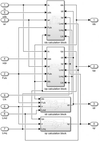
In the MATLAB/Simulink implementation, the mathematical model of the LSPMSM was divided into several functional subsystems in order to clearly represent the relationship between the theoretical equations and the simulation structure. The voltage and flux-linkage equations in the q–d axes were implemented as coupled differential equations using integrator blocks. Based on these equations, the stator and rotor current components, including $i_{s q}, i_{s d}, i_{r q}^{\prime}$ and $i_{r d}^{\prime}$, were calculated in the current calculation subsystem in the q–d axes, as shown in Figure 1.
Figure 1. Current calculation subsystem in the q–d axes of the line-start permanent magnet synchronous motor (LSPMSM) model in MATLAB/Simulink
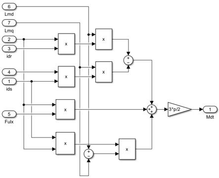
The calculated current components were then used as input variables for the electromagnetic torque calculation subsystem, as shown in Figure 2. In this subsystem, the electromagnetic torque was obtained from the interaction between the stator current components, rotor current components, permanent-magnet flux, the q- and d-axis magnetizing inductances. The torque calculation was implemented according to the electromagnetic torque expression presented in the theoretical model.
Figure 2. Electromagnetic torque calculation subsystem of the line-start permanent magnet synchronous motor (LSPMSM) model in MATLAB/Simulink
After the electrical subsystem was established, the mechanical subsystem was solved from the torque balance among the electromagnetic torque, load torque, and rotor inertia. The load torque was introduced as a constant input in the direct-on-line startup cases and as a step input during synchronous operation, following the values listed in Table 2. The initial speed was set to zero for the direct-on-line startup cases. In the load-increase cases, the motor first reached synchronous operation at the initial load, and then the additional load was applied at t = 2 s.
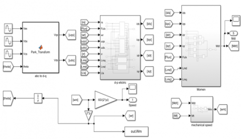
The overall MATLAB/Simulink model, which integrates the current calculation subsystem, torque calculation subsystem, mechanical subsystem, and load input block, is presented in Figure 3.
Figure 3. Overall MATLAB/Simulink model of the line-start permanent magnet synchronous motor (LSPMSM)
The proposed model is developed under the assumptions that the magnetic circuit operates in the unsaturated region and the rotor structure is symmetrical.
3.1 Startup process of the line-start permanent magnet synchronous motor under different load factors
To evaluate the startup load factor of the LSPMSM, this paper investigates different startup load factors by varying the load torque values, as listed in Table 2.
Table 2. Variation of load torque values
|
Scenarios |
Load Factor $K_{\mathrm{mt}}$ |
Load Torque $M_t=K_{m t} M_{d m}$ |
|
1 |
0 |
0 |
|
2 |
0.5 |
7 |
|
3 |
0.8 |
11.2 |
|
4 |
1 |
14 |
|
5 |
1.07 |
15 |
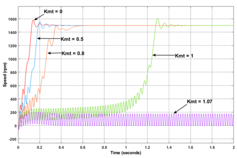
The startup speed characteristics corresponding to each load torque are shown in Figure 4.
Figure 4. The startup speed characteristics corresponding to each load torque
Figure 4 shows that under no-load and light-load conditions, corresponding to load factors of $K_{\mathrm{mt}}=0,0.5$, and 0.8, the LSPMSM starts easily and rapidly pulls into synchronism. As the load factor increases, the synchronization time becomes longer and the speed oscillation becomes more pronounced. At the rated load factor, $K_{\mathrm{mt}}=1$, the motor is still able to synchronize; however, the synchronization time increases significantly to approximately 1.6 s and the oscillation amplitude becomes larger. When the load factor exceeds the rated value, at $K_{\mathrm{mt}}=1.07$ corresponding to $M_t=15 \mathrm{~N} \cdot \mathrm{m}$, the motor fails to start successfully and cannot achieve synchronization. The evaluation of the startup performance of the LSPMSM under different load factors is summarized in Table 3.
Table 3. Parameters for evaluating the speed characteristics
|
$K_{\mathrm{mt}}$ |
$M_t$ |
Transient Time-tts (s) |
|
0 |
0 |
0.41 |
|
0.5 |
7 |
0.59 |
|
0.8 |
11.2 |
0.65 |
|
1 |
14 |
1.67 |
|
1.07 |
15 |
Cannot achieve synchronization |
From Table 3, it can be observed that the smaller the load, the faster the LSPMSM pulls into synchronism; however, the speed oscillation amplitude is larger. When the motor starts with 0.8 of the rated load torque, the speed oscillation amplitude is reduced. When the startup load reaches 15 N∙m, which exceeds the rated value, the motor fails to synchronize, and the speed characteristic exhibits strong oscillations around the range of 190-0 rpm.
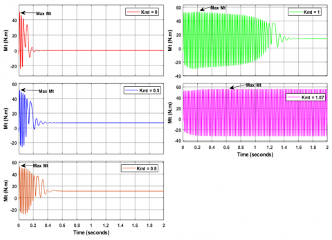
The electromagnetic torque characteristics of the LSPMSM are shown in Figure 5.
Figure 5. The startup electromagnetic torque characteristics for each load torque
Table 4. The electromagnetic torque characteristic parameters
|
$K_{\mathrm{mt}}$ |
$M_t$ |
Transient Time-tts (s) |
Maximum Electromagnetic Torque (N∙m) |
|
0 |
0 |
0.42 |
50.55 |
|
0.5 |
7 |
0.61 |
51.46 |
|
0.8 |
11.2 |
0.66 |
51.98 |
|
1 |
14 |
1.69 |
53.18 |
|
1.07 |
15 |
Loss of synchronism |
55.98 |
Figure 5 presents the startup electromagnetic torque responses of the LSPMSM under different load factors, and the corresponding characteristic values are summarized in Table 4. For $K_{\mathrm{mt}}$ = 0–1, the electromagnetic torque initially oscillates during startup and then gradually converges to a steady value after successful synchronization. As $K_{\mathrm{mt}}$ increases, the oscillation duration becomes longer, showing that the pull-in process becomes more difficult near rated load.
From Table 4, the maximum electromagnetic torque increases slightly from $50.55 \mathrm{~N} \cdot \mathrm{m}$ at $K_{\mathrm{mt}}=0$ to $53.18 \mathrm{~N} \cdot \mathrm{m}$ at $K_{\mathrm{mt}}=1.0$. When $K_{\mathrm{mt}}=1.07$, corresponding to $M_t=15 \mathrm{~N} \cdot \mathrm{m}$, the torque reaches a higher peak value of $55.98 \mathrm{~N} \cdot \mathrm{m}$ but exhibits strong non-decaying oscillations. This indicates loss of synchronism. Therefore, successful startup is determined not only by the peak electromagnetic torque but also by whether the torque oscillation decays and the motor reaches stable synchronous operation.
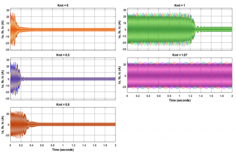
The startup current characteristics corresponding to each load torque are shown in Figure 6.
Figure 6. The startup current characteristics corresponding to each load torque
When starting with load factors ranging from $K_{\mathrm{mt}}$ = 0 to $K_{\mathrm{mt}}$ = 1, corresponding to 0 to 100% of the rated load, the amplitude of the starting current remains unchanged and reaches approximately 25 A. Thus, the starting current is about 6.5 times the rated current. This indicates that the LSPMSM draws a high transient current during startup, while the load factor mainly affects the duration of current oscillations and the steady-state operating current. These current characteristics are summarized in Table 5.
Table 5. Parameters for evaluating the current characteristics
|
$K_{\mathrm{mt}}$ |
$M_t$ |
Transient Time-tts (s) |
Operating Current (A) |
|
0 |
0 |
0.41 |
1.5 |
|
0.5 |
7 |
0.62 |
2.8 |
|
0.8 |
11.2 |
0.65 |
3.2 |
|
1 |
14 |
1.66 |
3.9 |
|
1.07 |
15 |
Loss of synchronism |
Loss of synchronism |
From Table 5, as the load factor increases from $K_{\mathrm{mt}}$ = 0 to $K_{\mathrm{mt}}$ = 1, the transient time of the current characteristics increases and reaches a maximum value of 1.66 s under rated load conditions. In addition, the steady-state operating current after successful startup also increases with load factor, ranging from 1.5 to 3.9 A. When the load factor exceeds the rated value, at $K_{\mathrm{mt}}$ = 1.07, the current exhibits strong and non-decaying oscillations with large amplitude and fails to converge, indicating loss of synchronism.
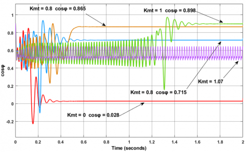
The power factor and efficiency are important characteristics reflecting the operating performance of the LSPMSM. Under different load factors, the power factor and efficiency of the motor are obtained as shown in Figures 7 and 8.
Figure 7. Power factor characteristics
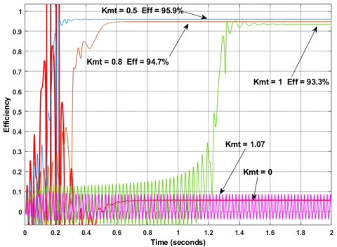
Figure 8. Efficiency characteristics
From Figures 7 and 8, during the transient period, the power factor (cosφ) and efficiency exhibit strong oscillations. After successful synchronization, both quantities gradually stabilize at steady values. However, when the load factor reaches $K_{\mathrm{mt}}$ = 1.07, the motor fails to synchronize; therefore, both the power factor and efficiency remain unstable. The steady-state values under at different load factors are summarized in Table 6.
Table 6. Power factor and efficiency values
|
$K_{\mathrm{mt}}$ |
$M_t$ |
Power Factor |
Efficiency (%) |
|
0 |
0 |
0.028 |
5.7 |
|
0.5 |
7 |
0.715 |
95.9 |
|
0.8 |
11.2 |
0.865 |
94.7 |
|
1 |
14 |
0.898 |
93.3 |
|
1.07 |
15 |
Fluctuates in the range of 0.5–0.7 |
Fluctuates (<9%) |
From Table 6, the load factor has a direct influence on the power factor and efficiency of the LSPMSM. Under no-load condition ($K_{\mathrm{mt}}=0$), the useful output power is nearly zero; therefore, the efficiency reaches only 5.7% and the power factor is almost zero. When the load increases to $K_{\mathrm{mt}}=0.5$ ($M_t =7 \mathrm{~N} \cdot \mathrm{m}$), the active current component becomes dominant, causing the power factor to rise sharply to 0.715 , while the efficiency reaches its peak value of 95.9%. As the load factor further increases to $K_{\mathrm{mt}}=0.8$ and $K_{\mathrm{mt}}=1$, the power factor increases to 0.865 and 0.898 , respectively, whereas the efficiency slightly decreases to 94.7% and 93.3%. When $K_{\mathrm{mt}}=$ 1.07, the motor loses synchronism, and both the power factor and efficiency become unstable. Overall, the power factor improves from no load to rated load, whereas the efficiency reaches its peak at a medium load and then gradually decreases.
3.2 Synchronization process of the line-start permanent magnet synchronous motor under load increase during operation
To evaluate the post-synchronization load capability, the motor was first operated in the synchronous state with an initial load torque of 12 N∙m. At t = 2 s, the load torque is increased stepwise to the values listed in Table 7.
Table 7. Increased load torque values
|
Scenarios |
Load Factor $K_{\mathrm{mt}}$ |
Load Torque $M_t=\mathrm{K}_{\mathrm{mt}} M_{\mathrm{dm}}$ |
|
1 |
1.07 |
15 |
|
2 |
1.29 |
18 |
|
3 |
1.5 |
21 |
|
4 |
1.79 |
25 |
|
5 |
1.86 |
26 |
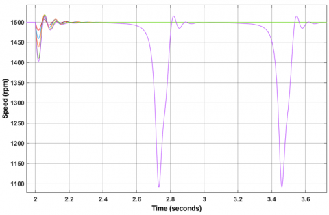
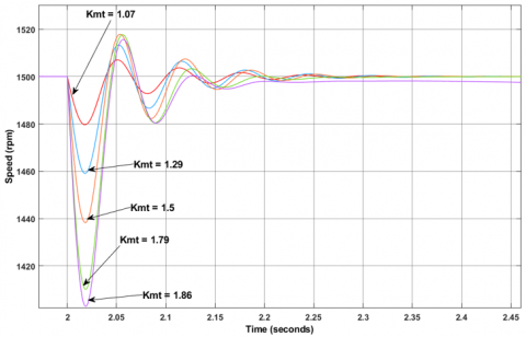
The speed characteristics of the motor under post-synchronization load increase are shown in Figure 9.
(a)
(b)
Figure 9. Speed response of the LSPMSM under post-synchronization load increase: (a) overall response; (b) enlarged transient response around the load-changing instant
From Figure 9, it can be observed that when the load is suddenly increased after the motor has reached synchronous operation, the motor speed initially drops and then oscillates before returning to the vicinity of synchronous speed. As the load factor increases, the speed drop and the transient oscillation become more significant. For $K_{\mathrm{mt}}$ = 1.07, 1.29, 1.5, and 1.79, the LSPMSM can recover after the transient period and maintain synchronous operation. However, when the load factor increases to $K_{\mathrm{mt}}$ = 1.86, the motor can no longer maintain stable synchronism. The characteristic parameters of the speed response are summarized in Table 8.
Table 8. Characteristic parameters of the speed
|
$K_{\mathrm{mt}}$ |
$M_t$ |
Transient Time-tts (s) |
Additional Load Torque $\Delta \mathbf{M}_t$ (N∙m) |
Speed Deviation Max $\Delta \mathbf{n}$ (rpm) |
|
1.07 |
15 |
0.3 |
3 |
20 |
|
1.29 |
18 |
0.35 |
6 |
41 |
|
1.5 |
21 |
0.45 |
9 |
62 |
|
1.79 |
25 |
0.50 |
13 |
90 |
|
1.86 |
26 |
Loss of synchronism |
14 |
97 |
From Table 8, within the stable synchronization range from $K_{\mathrm{mt}}=1.07$ to $K_{\mathrm{mt}}=1.79$, the maximum speed deviation increases almost linearly with the additional load torque. This relationship can be approximately expressed as $\Delta n \approx 6,85 \Delta M_t$. Therefore, the maximum speed deviation of the tested LSPMSM under a sudden load increase can be estimated when the motor still maintains synchronism.
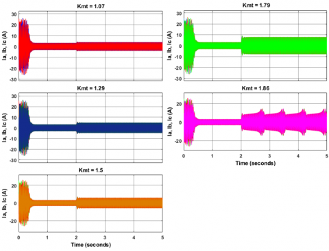
Figure 10. Current characteristics of the line-start permanent magnet synchronous motor (LSPMSM) under post-synchronization load increase
Compared with the startup case presented in Section 3.1, the motor can maintain synchronization under a much higher load level after it has already reached synchronous operation. When the load factor increases to $K_{\mathrm{mt}}$ = 1.79, corresponding to $M_t$ = 25 N∙m, the motor still maintains synchronization and requires in approximately 0.5 s to recover. When $K_{\mathrm{mt}}$ = 1.86, corresponding to 26 N∙m, the motor speed reaches 1498 rpm after 0.3 s but can be maintained for only 0.16 s before rapidly dropping to about 1092 rpm, and this behavior repeats, indicating a loss of synchronism. Thus, $K_{\mathrm{mt}}$ = 1.79 is the maximum load torque at which the motor can maintain synchronization in the simulated post-synchronization load-increase case. A two-step operating strategy can therefore be used for high-load operation: the motor first starts under a medium or rated load to reach synchronous speed, and the load is then increased after synchronization. With this strategy, the investigated LSPMSM can reach $K_{\mathrm{mt}}$ = 1.79 under short-term load-increase conditions.
The current characteristics under post-synchronization load increase are shown in Figure 10.
From Figure 10, increasing the load after the motor has reached synchronous operation causes transient oscillations in the stator current. As the additional load torque increases, both the current amplitude and the oscillation duration become larger. In particular, when the additional load torque reaches $\Delta M_t$ = 14 N∙m, corresponding to $K_{\mathrm{mt}}$ = 1.86, the current does not converge to a steady value, indicating loss of synchronism. The corresponding characteristic parameters are summarized in Table 9.
Table 9. Characteristic parameters of the current
|
Additional Load Torque $\Delta \mathrm{M}_t$ (N∙m) |
Transient Time-tts (s) |
Peak Current $I_{\max}$ (A) |
Steady-State Current $I_{\mathrm{dm}}$ (A) |
Current Multiple $I_{\max} / I_{\mathrm{dm}}$ |
|
3 |
0.29 |
4.5 |
4.01 |
1.12 |
|
6 |
0.36 |
5.6 |
4.86 |
1.15 |
|
9 |
0.44 |
6.9 |
5.89 |
1.17 |
|
13 |
0.49 |
9.6 |
7.93 |
1.20 |
|
14 |
Loss of synchronism |
18 |
Loss of synchronism |
--- |
From Table 9, it can be observed that the oscillation duration tends to increase with the additional load torque. When $\Delta M_t$ increases from 3 N∙m to 13 N∙m, the transient time increases from 0.29 s to 0.49 s. At the same time, the peak current increases from 4.5 A to 9.6 A, while the steady-state current increases from 4.01 A to 7.93 A. The current multiple Imax/Idm also increases from 1.12 to 1.20, indicating a higher electrical stress under larger load increments.
When $\Delta M_t$ = 14 N∙m, corresponding to $K_{\mathrm{mt}}$ = 1.86, the motor loses synchronism and the current exhibits large non-decaying oscillations. This increase in current may intensify copper losses, temperature rise, and the risk of permanent-magnet demagnetization. Therefore, the allowable load increase should be selected with respect to both synchronization capability and thermal/demagnetization limits.
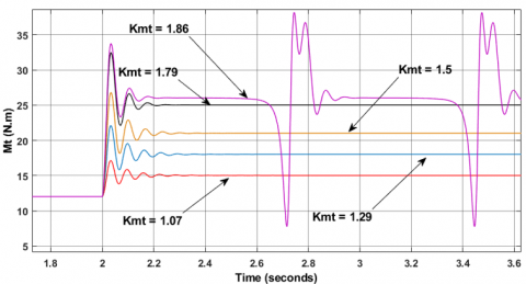
The electromagnetic torque characteristics of the LSPMSM under post-synchronization load increase are shown in Figure 11.
Figure 11. Electromagnetic torque characteristics of the line-start permanent magnet synchronous motor (LSPMSM) under post-synchronization load increase
Figure 11 shows that, at the moment of a sudden load increase, the electromagnetic torque rises sharply and then oscillates before settling to a new steady value. However, at $K_{\mathrm{mt}}$ = 1.86, corresponding to $M_t$ = 26 N∙m and $\Delta M_t$ = 14 N∙m, the torque remains stable for only about 0.16 s and then exhibits strong non-decaying oscillations with large amplitude, indicating loss of synchronism. The electromagnetic torque parameters are summarized in Table 10.
Table 10. Characteristic parameters of the electromagnetic torque
|
$K_{\mathrm{mt}}$ |
Additional Load Torque $\Delta \mathbf{M}_t$ (N∙m) |
Transient Time-tts (s) |
Peak Torque $M_{\max}$ (N∙m) |
Torque Multiple $\frac{M_{\max}}{M_{\mathrm{dm}}}$ |
|
1.07 |
3 |
0.29 |
16.5 |
1.1 |
|
1.29 |
6 |
0.36 |
22.6 |
1.22 |
|
1.5 |
9 |
0.44 |
26.5 |
1.26 |
|
1.79 |
13 |
0.49 |
33.0 |
1.32 |
|
1.86 |
14 |
Loss of synchronism |
Loss of synchronism |
--- |
The results in Table 10 indicate that increasing the load while the LSPMSM has reached synchronous operation intensifies torque oscillations. When $\Delta M_t$ increases from 3 N∙m to 13 N∙m, the transient time increases from 0.29 s to 0.49 s, while the peak electromagnetic torque increases from 16.5 N∙m to 33.0 N∙m. The torque multiple $\frac{M_{\text {max}}}{M_{\mathrm{dm}}}$ also increases from 1.10 to 1.32, showing that a larger load increment produces higher transient mechanical stress.
Although the motor maintains synchronization up to $K_{\mathrm{mt}}$ = 1.79 ( $M_t$ = 25 N∙m) in the simulated post-synchronization load-increase case, this condition should be interpreted as a short-term overload capability rather than a recommended continuous operating point. At $K_{\mathrm{mt}}$ = 1.86, the torque does not converge, indicating loss of synchronism. The transient torque pulses and current oscillations observed under high load may increase mechanical vibration and cyclic stress on the shaft, bearings, coupling, and rotor cage. Therefore, a conservative overload limit lower than the simulated boundary should be adopted for practical operation.
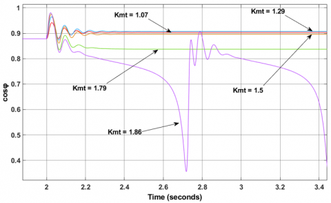
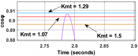
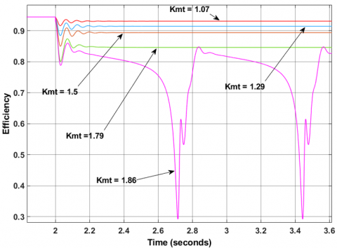
When the load is increased while the LSPMSM is operating in the synchronous state, the power factor and efficiency characteristics are obtained as shown in Figures 12 and 13.
From Figures 12 and 13, the variations in the power factor and efficiency characteristics under sudden post-synchronization load increase can be clearly observed, as detailed in Table 11.
From Table 11, the power factor slightly increases when the load factor from $K_{\mathrm{mt}}$ = 1.07 to $K_{\mathrm{mt}}$ = 1.29, corresponding to an increase in load torque from 15 N∙m to 18 N∙m. After that, the power factor decreases as the load factor further increases to $K_{\mathrm{mt}}$ = 1.5 and $K_{\mathrm{mt}}$ = 1.79. The efficiency decreases gradually with increasing load factor, from 93% at $K_{\mathrm{mt}}$ = 1.07 to 85% at $K_{\mathrm{mt}}$ = 1.79, indicating efficiency degradation under overload operation.
(a)
(b)
Figure 12. Power factor characteristics of the line-start permanent magnet synchronous motor (LSPMSM) under post-synchronization load increase: (a) overall response; (b) enlarged view of the steady-state power factor
Figure 13. Efficiency characteristics of the line-start permanent magnet synchronous motor (LSPMSM) under post-synchronization load increase
When the load factor reaches $K_{\mathrm{mt}}$ = 1.86, corresponding to $M_t$ = 26 N∙m, both the power factor and efficiency fluctuate significantly because the motor loses synchronism. Therefore, although the motor can maintain synchronization up to $K_{\mathrm{mt}}$ = 1.79 in the simulated short-term load-increase condition, operation at high overload levels is not recommended for long-term use due to efficiency degradation and unstable operating characteristics near the synchronization limit.
Table 11. Characteristic parameters of the power factor and efficiency
|
$\boldsymbol{K}_{\mathrm{mt}}$ |
$M_t$ |
Power Factor |
Efficiency (%) |
|
1.07 |
15 |
0.903 |
93 |
|
1.29 |
18 |
0.907 |
91 |
|
1.5 |
21 |
0.896 |
89 |
|
1.79 |
25 |
0.837 |
85 |
|
1.86 |
26 |
Fluctuates in the range of 0.36–0.91 |
Fluctuates in the range of 0.29–0.85 |
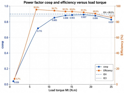
In combination with Tables 6 and 11, a plot illustrating the influence of load torque on the power factor and efficiency of the LSPMSM is obtained, as shown in Figure 14.
Figure 14. Power factor and efficiency comparison under different load levels
From Figure 14, it can be observed that both the power factor (cosφ) and the efficiency of the LSPMSM vary significantly with load torque. In the low-load region, the power factor and efficiency increase rapidly as the motor transitions from no-load to loaded operation, thereby reducing the impact of no-load losses. When the load torque is in the range of approximately 10-15 N∙m, both cosφ and efficiency remain at high values, with cosφ around 0.90 and efficiency exceeding 93%, indicating that this is a suitable operating region of the motor in terms of both electrical and mechanical performance. However, when the motor operates at load levels exceeding 15 N∙m, the efficiency begins to decrease gradually, while the power factor also slightly decreases or exhibits unstable fluctuations near the synchronization limit.
The reduction in efficiency under overload operation can be physically explained by the increase in stator current and torque-angle oscillation. As the load torque increases, the active current component rises to produce the required electromagnetic torque, which increases the stator copper loss approximately according to $P_{c u}=3 . I_s^2 . r_s$. In addition, overload operation may intensify local magnetic saturation, iron loss, stray-load loss, and temperature-dependent resistance increase. These effects reduce the net output-to-input power ratio. The power factor initially improves as the useful active power increases from no-load to rated-load operation; however, at high overload levels, the oscillation of the torque angle and the increased reactive component cause the power factor to decrease or fluctuate. This explains why the 10–15 N∙m range is more suitable for efficient continuous operation, whereas higher overload levels should be used only for short-term operation.
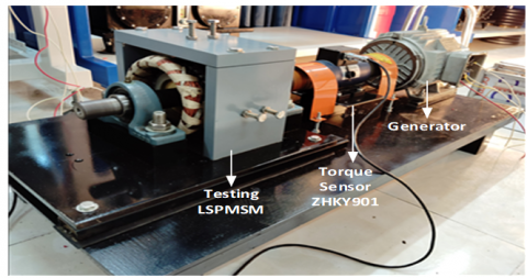
To experimentally validate the research findings, a 2.2 kW, 2-pole pair (2p = 4) LSPMSM was manufactured by the research team, and an experimental testbench was established, as shown in Figure 15.
Figure 15. The model setup in the laboratory
In the experimental setup, the 2.2 kW LSPMSM is directly coupled to a generator. By varying the load on the generator, the load applied to the LSPMSM is correspondingly adjusted. The operating efficiency is calculated as follows [31]:
$\eta=\frac{P_2}{P_1}$ (47)
where, $P_2(\mathrm{~W})$ is the output mechanical power at the motor shaft, $P_1(\mathrm{~W})$ is the electrical input power to the motor, measured using the LWDSS1 wattmeter. To improve measurement accuracy, the ZHKY901 torque sensor is employed to determine $P_2$ based on the measured torque and rotational speed using the following equations:
$P_2=M \cdot \omega=M \cdot 2 \pi \frac{n}{60}$ (48)
where, $\omega, \,n$ is the angular speed and the rotational speed of the rotor. In the experiment, $M$ and $n$ are measured directly using the ZHKY901 sensor and a DAQ device.
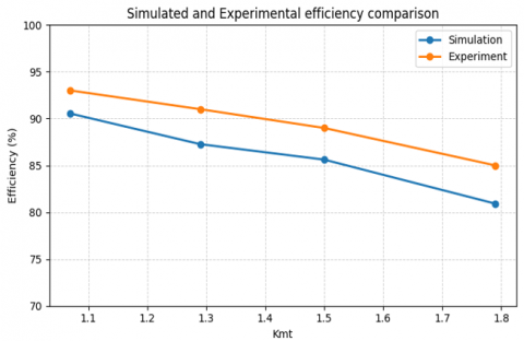
The measured efficiency of the motor under varying load conditions in the laboratory is summarized in Figure 16.
Figure 16. Simulated and experimental efficiency comparison
The experimental results shown in Figure 16 indicate that the measured efficiency ranges from 80.9% to 90.5%, which is slightly lower than the simulated efficiency. This difference can be attributed to manufacturing tolerances, measurement uncertainty, and practical losses that are not fully included in the simulation model. In the experiment, the output power is calculated from the measured torque and speed, whereas the input power is obtained from the wattmeter. Therefore, the uncertainty of the torque sensor, speed acquisition, and wattmeter directly affects the calculated efficiency. In addition, bearing friction, coupling loss, stray-load loss, temperature-dependent resistance variation, local magnetic saturation, and non-uniform magnetic-field distribution may further reduce the measured efficiency. Despite these differences, the experimental data follow the same load-dependent trend as the simulation results, supporting the reliability of the simulation model for evaluating the investigated LSPMSM.
The LSPMSM is known for several advantages, such as high efficiency and self-starting capability without the need for auxiliary starting devices, unlike conventional PMSMs. This study conducted simulations of two important scenarios: direct-on-line startup under different load torque levels and sudden load increase after the motor had reached synchronous operation, using a 2.2 kW–1500 rpm LSPMSM.
During direct-on-line startup under different load torque levels, the results indicate that the motor can successfully start and pull into stable synchronism with load torque up to 14 N∙m (100% of the rated load). At 15 N∙m, the startup process fails, as the speed does not exceed 1460 rpm and the electromagnetic torque exhibits strong oscillations. The pull-in synchronization time increases gradually from about 0.4 s under no-load/light-load conditions to about 1.6–1.7 s at rated load, while the amplitudes of current and torque oscillations also become larger. The startup efficiency reaches its maximum value of 95.9% at 7 N∙m but decreases to 93.3% as the load increases to 14 N∙m; meanwhile, the power factor increases nearly linearly with load, reaching 0.898 at this maximum load level, whereas it is nearly zero under no-load conditions.
When the load is increased while the LSPMSM is operating in the synchronous state, the motor speed exhibits oscillations and consistently deviates from the synchronous speed by an amount Δn of approximately 6.85 rpm for each 1 N∙m increase in load torque; this relationship shows a deviation of less than 5% compared with the simulation results. The motor can withstand short-term overload up to 25 N∙m (overload factor of 1.79) while maintaining synchronization, with a maximum speed drop of 90 rpm and recovery within 0.5 s; however, at 26 N∙m, the motor loses synchronism after only 0.16 s. When the load exceeds 18 N∙m, the efficiency decreases rapidly, reaching only 85% at 25 N∙m, and the power factor also deteriorates.
Experimental tests were carried out under selected operating points to support the simulation results. The measured efficiency trends closely follow the simulation prediction, although the measured values are lower due to additional practical losses, measurement uncertainty, magnetic saturation effects, and manufacturing tolerances. This agreement confirms the decreasing efficiency trend with increasing load torque and supports the reliability of the simulation-based dynamic analysis for the tested motor.
Based on the combined simulation and experimental findings, the authors recommend limiting the startup load torque to below 0.95 of the rated load (13.3 N∙m) in order to ensure rapid pull-in synchronization and to reduce the duration of transient oscillations and starting stress. After synchronization is achieved, the short-term overload should be limited to below 1.6 times the rated load (22 N∙m) to avoid efficiency degradation and overheating. The empirical relationship $\Delta n \approx 6,85 \Delta M_t$ proposed in this study can be integrated into slip protection algorithms or speed-drop control strategies, thereby improving the reliability of LSPMSM-based drive systems under variable load conditions.
It should be noted that the coefficient 6.85 rpm/N∙m is an empirical coefficient obtained for the investigated 2.2 kW, 1500 rpm LSPMSM under the specific simulated condition in which the load was increased from an initial synchronous operating point of 12 N∙m. In this study, the relationship is applicable to the additional-load range of 3–13 N∙m, where the motor still returns to synchronous operation after the transient oscillation. Therefore, this coefficient should not be regarded as a universal constant for all LSPMSM designs. For motors with different inertia, rotor structure, magnet dimensions, supply conditions, or load type, the coefficient must be recalibrated before being used in slip protection or speed-drop control.
From a practical viewpoint, the obtained results support a two-stage operating strategy for LSPMSM-driven loads. For fan or pump systems, the motor should preferably start under a reduced mechanical load, for example by partially closing a valve or reducing the initial hydraulic load, and the load can then be increased after synchronization is established. This strategy reduces the risk of pull-in failure during direct-on-line startup while still allowing a higher short-term load after synchronization.
The present model is based on the assumptions of an unsaturated magnetic circuit and a symmetrical rotor structure, which are suitable for clarifying the main synchronization trend of the investigated motor. However, under severe overload or long-term operation, local saturation, temperature rise, magnet aging, and mechanical fatigue may change the torque and synchronization characteristics. Therefore, the obtained synchronization boundary should be interpreted as the simulated and experimentally validated boundary for the tested motor and operating conditions. Future work will include thermal-coupled modeling, saturation effects, and long-duration overload tests to further evaluate the robustness of the proposed operating limits.
[1] Vannini, A., Simonelli, C., Marfoli, A., Papini, L., Bolognesi, P., Gerada, C. (2022). Modelling, analysis, and design of a line-start permanent magnet synchronous motor. In 2022 International Conference on Electrical Machines (ICEM), Valencia, Spain, pp. 834-840. https://doi.org/10.1109/ICEM51905.2022.9910937
[2] Isfahani, A.H., Vaez-Zadeh, S. (2009). Line start permanent magnet synchronous motors: Challenges and opportunities. Energy, 34(11): 1755-1763. https://doi.org/10.1016/j.energy.2009.04.022
[3] Duc, H.B., Minh, D.B., Quoc, V.D. (2022). Analytical and FEM methods for line start permanent magnet synchronous motor of 2.2 kW. Journal Européen des Systèmes Automatisés, 55(6): 715-721. https://doi.org/10.18280/jesa.550603
[4] Kurihara, K., Rahman, M.A. (2004). High-efficiency line-start interior permanent-magnet synchronous motors. IEEE Transactions on Industry Applications, 40(3): 789-796. https://doi.org/10.1109/TIA.2004.827476
[5] Gwozdziewicz, M., Zalas, P., Zawilak, J. (2017). Starting process of medium power line start permanent magnet synchronous motor. Przegląd Elektrotechniczny, 93(2): 62-64. https://doi.org/10.15199/48.2017.02.15
[6] Park, H.J., Hong, H.B., Lee, K.D. (2022). A study on a design considering the transient state of a line-start permanent magnet synchronous motor satisfying the requirements of the IE4 efficiency class. Energies, 15(24): 9644. https://doi.org/10.3390/en15249644
[7] Stoia, D., Chirilă, O., Cernat, M., Hameyer, K., Ban, D. (2010). The behaviour of the LSPMSM in asynchronous operation. In Proceedings of 14th International Power Electronics and Motion Control Conference EPE-PEMC 2010, Ohrid, Macedonia, pp. T4-45-T4-50. https://doi.org/10.1109/EPEPEMC.2010.5606795
[8] Pecho, J., Hofmann, W. (2018). Analysis of start-up of line-start permanent magnet synchronous machines with anisotropic rotor reluctance. In 2018 XIII International Conference on Electrical Machines (ICEM), Alexandroupoli, Greece, pp. 72-78. https://doi.org/10.1109/icelmach.2018.8506720
[9] Wymeerschl, B., De Belie, F., Rasmussen, C.B., Vandevelde, L. (2018). The effect of design considerations on the synchronization capability limits of line-start permanent-magnet synchronous motors. In 2018 XIII International Conference on Electrical Machines (ICEM), Alexandroupoli, Greece, pp. 988-994. https://doi.org/10.1109/icelmach.2018.8506734
[10] Jedryczka, C., Wojciechowski, R.M., Demenko, A. (2015). Influence of squirrel cage geometry on the synchronisation of the line start permanent magnet synchronous motor. IET Science, Measurement & Technology, 9(2): 197-203. https://doi.org/10.1049/iet-smt.2014.0198
[11] Paramonov, A., Oshurbekov, S., Kazakbaev, V., Prakht, V., Dmitrievskii, V. (2022). Study of the effect of throttling on the success of starting a line-start permanent magnet motor driving a centrifugal fan. Mathematics, 10(22): 4324. https://doi.org/10.3390/math10224324
[12] Chama, A., Sorgdrager, A.J., Wang, R.J. (2016). Analytical synchronization analysis of line-start permanent magnet synchronous motors. Progress In Electromagnetics Research M, 48: 183-193. https://doi.org/10.2528/pierm16050311
[13] Schommarz, P., Wang, R.J. (2022). Development of a transient synchronization analysis tool for line-start PM motors. Energies, 15(23): 9206. https://doi.org/10.3390/en15239206
[14] Akçomak, M., Zorlu Partal, S. (2024). Design of a 2.2 kW 4-Pole IE5 efficiency class line-start permanent magnet synchronous motor. In 2024 6th Global Power, Energy and Communication Conference (GPECOM), Budapest, Hungary, pp. 190-198. https://doi.org/10.1109/GPECOM61896.2024.10582573
[15] Sethupathi, P., Senthilnathan, N., Atshaya, M. (2022). Rotor topology to reach beyond IE5 ultra-premium efficiency in line start permanent magnet synchronous motor. Research Square. https://doi.org/10.21203/rs.3.rs-2049192/v1
[16] Ocak, C., Yenipınar, B., Çelik, E., Abdel-Salam, M., Tejani, G.G., Mousavirad, S.J. (2025). Design optimization and real-time implementation of an LSPMSM for efficiency enhancement. Scientific Reports, 15: 37975. https://doi.org/10.1038/s41598-025-21896-5
[17] Parivar, H., Seyyedbarzegar, S.M., Darabi, A. (2021). An improvement on slot configuration structure of a low-speed surface-mounted permanent magnet synchronous generator with a wound cable winding. International Journal of Engineering, 34(9): 2045-2052. https://doi.org/10.5829/ije.2021.34.09c.01
[18] Yan, B., Yang, Y.B., Wang, X.H. (2021). A semi-numerical method to assess start and synchronization performance of a line-start permanent magnet synchronous motor equipped with hybrid rotor. IET Electric Power Applications, 15(4): 487-500. https://doi.org/10.1049/elp2.12043
[19] Yang, Y.B., Yan, B., Wang, X.H. (2024). Quantitative assessment on synchronisation capability of a line-start permanent magnet synchronous motor with hybrid rotor. IET Electric Power Applications, 18(2): 141-152. https://doi.org/10.1049/elp2.12373
[20] Soulard, J., Nee, H.P. (2000). Study of the synchronization of line-start permanent magnet synchronous motors. In Conference Record of the 2000 IEEE Industry Applications Conference. Thirty-Fifth IAS Annual Meeting and World Conference on Industrial Applications of Electrical Energy (Cat. No. 00CH37129), Rome, Italy, pp. 424-431. https://doi.org/10.1109/IAS.2000.881145
[21] Isfahani, A.H., Vaez-Zadeh, S., Rahman, M.A. (2011). Evaluation of synchronization capability in line start permanent magnet synchronous motors. In 2011 IEEE International Electric Machines & Drives Conference (IEMDC), Niagara Falls, ON, Canada, pp. 1346-1350. IEEE. https://doi.org/10.1109/iemdc.2011.5994801
[22] Truong Cong, T., Nguyen Vu, T., Bui Minh, D., Vo Thanh, H., Dang Quoc, V. (2024). Analytical modelling of a six-phase surface mounted permanent magnet synchronous motor. International Journal of Engineering, 37(7): 1274-1283. https://doi.org/10.5829/ije.2024.37.07a.07
[23] Chaudhari, M., Chowdhury, A. (2022). Improved performance analysis of single-phase line start synchronous reluctance motor derived from induction motor. International Journal of Engineering, 35(8): 1641-1650. https://doi.org/10.5829/ije.2022.35.08b.20
[24] Quoc, V.D., Huu, H.B. (2024). Modeling of surface-mounted permanent magnet synchronous motors with inner and outer rotor types. International Journal of Engineering, 37(12): 2529-2537. https://doi.org/10.5829/ije.2024.37.12c.11
[25] Sultan, A.J., Abdollahi, S.E., Gholamian, S.A. (2026). Design optimization of a permanent magnet-assisted synchronous reluctance motor. International Journal of Engineering, 39(3): 658-667. https://doi.org/10.5829/ije.2026.39.03c.08
[26] Faiz, J., Rafiei, V. (2024). Design of a three-phase outer rotor synchronous motor for hybrid vehicle. International Journal of Engineering, 37(11): 2380-2391. https://doi.org/10.5829/ije.2024.37.11b.22
[27] Sen, A., Singh, B., Moradzadeh, A., Mahtani, K. (2025). Permanent magnet brushless DC motor sensorless control for solar-powered and grid-integrated water-pumping systems. International Journal of Engineering, 38(11): 2760-2775. https://doi.org/10.5829/ije.2025.38.11b.22
[28] Rabbi, S.F., Rahman, M.A. (2013). Critical criteria for successful synchronization of line-start IPM motors. IEEE Journal of Emerging and Selected Topics in Power Electronics, 2(2): 348-358. https://doi.org/10.1109/jestpe.2013.2295178
[29] Isfahani, A.H., Vaez-Zadeh, S. (2011). Effects of magnetizing inductance on start-up and synchronization of line-start permanent-magnet synchronous motors. IEEE Transactions on Magnetics, 47(4): 823-829. https://doi.org/10.1109/TMAG.2010.2091651
[30] Le, A.T., Lan, N.T., Do, N.Y., Bun, H.V. (2025). Studying the effect of PM thickness on the Back-EMF and power factor of LSPMSM. Journal Européen des Systèmes Automatisés, 58(3): 493-500. https://doi.org/10.18280/jesa.580307
[31] Le, T.A., Lan, N.T., Do, N.Y. (2026). Investigating the size of permanent magnets to maximize the LSPMSM’s efficiency. International Journal of Engineering, 39(6): 1369-1381. https://doi.org/10.5829/ije.2026.39.06c.06