Habiba Becha![]() | Badis Bakri
| Badis Bakri![]() | Hani Benguesmia*
| Hani Benguesmia*![]() | Yasmine Mekkas
| Yasmine Mekkas![]() | Mohammed Benguesmia
| Mohammed Benguesmia![]() | Faiza Nesssark
| Faiza Nesssark![]() | Nassima M’ziou
| Nassima M’ziou![]()
© 2026 The authors. This article is published by IIETA and is licensed under the CC BY 4.0 license (http://creativecommons.org/licenses/by/4.0/).
OPEN ACCESS
This research employs finite element method (FEM)-based two-dimensional electrostatic simulations to investigate how dielectric barriers affect the dielectric strength and electric field profile in point–plane air gaps under alternating current (AC) voltage conditions. The primary objective is to examine how these barriers modify the potential and electric field distributions in vertical gaps by comparing configurations with and without dielectric barriers. The results show that dielectric barriers significantly modify the original electric field configuration, creating a more uniform electric field distribution and reducing localized electric field intensification. These modified electric field distributions enhance the overall dielectric strength of the gap and increase its withstand voltage prior to electrical breakdown. Accordingly, the findings highlight the important role of dielectric barriers in high-voltage insulation systems, where proper design and placement can effectively mitigate electric field concentrations and thereby reduce the likelihood of insulation failure, thus improving the reliability of power transmission components. Furthermore, the results provide a fundamental analytical basis for improving insulation system design and for developing higher-performance and more efficient high-voltage insulation structures.
point-plane air gap, electric potentials, dielectric barriers, electric fields, finite element method
Insulating barriers are commonly used to change and enhance the breakdown strength of high-voltage (HV) systems, by altering the electric field in the system. When you place a dielectric barrier between the electrodes of a point-to-plane geometry, which has an extremely divergent field, the dielectric barrier significantly changes the electrostatic field profile. Many studies have shown that a dielectric barrier's permittivity changes how the electric field is affected by that dielectric barrier [1-3]. However, there has been less systematic research on how the physical dimensions of the dielectric barrier ultimately affect the overall distribution of the electric field. Surface charge buildup on the dielectric barrier due to pre-discharge events or previous conditioning leads to localized electric field distortion, which complicates how the electric fields are distributed to the dielectric material at the point-to-plane interface. Additional stress is created within the entire dielectric barrier system due to this localized distortion and may negatively impact the overall dielectric performance of the point-to-plane interface [4-6].
Many experimental and numerical experiments have been used by researchers to study barrier discharges in alternating current (AC) and pulse loads [7-11]. However, an electrostatic study of these phenomena must be established before we can understand what conditions were present at the point of development for such dynamic electrostatic phenomena. Therefore, it is important to note that the use of an electrode electrostatics approach alone does not provide a dynamic model of AC charge buildup or transient discharges; rather, it gives us an electrostatic of the initial configuration of the electric field associated with barrier device electrodes and isolates and quantifies the geometric and material characteristics that contributed to the creation of that initial electric field configuration.
A finite element method (FEM) model will be used to solve Laplace's equation numerically and effectively for point-plane electrode-dielectric structures, specifically to determine how dielectric barrier width affects the electrostatic field of an air-filled, point-plane air gap. By changing the barrier width and evaluating the resulting field strength, field distortion, and field stresses, this research will quantify, through geometric parameters alone, the contribution of geometry to the generation of electrostatic charged space in the barrier-modified air gap. This work will be the beginning of developing advanced models incorporating space charge and the effects of time.
The current research is divided into four sections. In the second section, a description of the simulation model is presented, including the definition of the problem, geometry, material properties, boundary conditions, meshing, and solution through FEM. The third section is dedicated to providing the results and discussions related to electric potential and field distribution with gaps involving points and planes with different widths of dielectric barriers, and finally, the conclusion is presented in Section 4.
The influence of a dielectric barrier on the electric field and voltage distribution was analysed using FEMM software, which is based on FEM [1, 12-14].
In these models, the pre-breakdown instant was simulated in the electrostatics of FEMM software.
To find the electric field and voltage distribution, first, each system geometry was plotted in the computational domain. Boundary conditions, including surface charge distribution, material properties, and applied voltage to HV electrodes, were entered into the simulation model. The boundary conditions used in the simulation are described in the following section. Then, the electric field and voltage distributions in the air gap are calculated using Laplace's equation [15-20]:
$-\nabla(\varepsilon V)=0$ (1)
$E=-\nabla V$ (2)
where, E and V are the electric field and potential, respectively, and ε is the permittivity coefficient.
To study the configuration of a point plane with and without a barrier of different widths using the FEM in electrostatic cases, follow these resolution steps:
2.1 Problem definition and geometry setup
•Choose electrostatics as the governing physical phenomenon,
•Create the geometric model of the point-plane configuration,
•Include the barrier in the geometry for cases that require it,
•Ensure models are created with varying barrier widths to study their effects,
•Ensure the physics setup includes necessary boundary conditions and material properties.
2.2 Material properties and boundary conditions
•Assign electrical properties such as permittivity to the materials in the geometry (air, barrier material, etc.).
•The insulating barrier possesses a relative permittivity of εr = 6 and a conductivity of σ = 10-14.
•The conductive core comprises copper electrodes with a relative permittivity of εr = 106 and conductivity of σ = 106.
•The surrounding air in the insulator model has a permittivity of εr = 1.0005 and a conductivity of σ = 10-14.
•Set the appropriate boundary conditions for the problem, such as electric potential on the point (source) and grounded plane. In our work, the boundary conditions are set as V = 10000 Volts on the point, V = 0 Volts (ground) on the plane, and ∂V/∂n = 0 on all remaining outer boundaries.
2.3 Meshing the geometry
•Discretize the geometry into finite elements.
•Ensure the mesh is fine enough to capture the details around critical areas like the point, plane, and barriers.
2.4 Solving the system of equations
•Choose the appropriate solvers and algorithms to solve the discretized equations in our cases presented in Eq. (1),
•Configure solver settings to ensure convergence and accuracy,
•Run the solver to obtain the electrostatic potential and field distribution,
•Plot the electric field distribution and potential in the geometry,
•Compare the results for configurations with and without barriers.
2.5 Analyze results
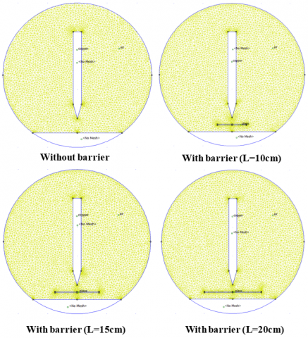
An electrostatic simulation in two dimensions has been developed that allows for the analysis of the capacitive field distribution within a point-plane electrode system that also has an insulating barrier present. Figure 1 shows the primary configuration's key geometries and dimensions along with its boundary conditions.

Figure 1. Point-plane arrangement, (a) without barrier, (b) with barrier (L = 10 cm), (c) with barrier (L = 15 cm), (d) with barrier (L = 20 cm)
Using the validated model, this analysis was conducted with a comparative methodology. The first step was to conduct a baseline simulation of the bare point-to-plane gap for establishing the reference electric field distribution from which to compare subsequent results relative to the distortion of that electric field. In the next step of the analysis, simulations were performed for barrier widths of 10 cm, 15 cm, and 20 cm. The purpose of these barrier width simulations was to address two fundamental objectives:
•To analyze qualitatively and quantitatively how the electric field would be distorted by each width, particularly the areas of electric field enhancement and reduction.
•To establish quantitative values for the electric field at both the point tip (maximum) and on the barrier surface, including the potential profile along the centerline of the gap.
All of the data from these simulation results, including two-dimensional electric field contour maps, electric potential distribution maps, and comparative tables, were organized into an extensive report summarizing the purpose, methodology, analytical results of the study, and the conclusion that a barrier has a significant effect on the electric field.
We will simulate our configurations using the two-dimensional software "FEMM". Figures 1(a, b, c, and d) depict our model's configuration, providing a clear representation.
3.1 Meshing
Mesh design plays an important role in obtaining accurate results for point-plane air gaps in numerical simulations of electric fields and their governing physical principles. A given mesh will not only affect the overall accuracy of the simulation, but also impact the computational efficiency of the simulation.
Figure 2. Discretization by finite elements mesh of arrangement point-plan with and without barrier
Near sharp geometrical edges (i.e., electrode tips), finer mesh sizes need to be used to resolve the high gradient areas of the electric fields. On the other hand, coarser mesh sizes can be used in areas where there is little to no variation in the field.
A structured triangular mesh will be used for the 2-D point-barrier-plane domain in this research study (Figure 2 shows an example of the mesh scheme for a point-barrier-plane domain). Table 1 provides the mesh characteristics that were used to establish the accuracy of the results for the mesh used in the baseline (i.e., with no barrier to the point-plane).
Table 1. Characteristic of the meshing
|
|
Without Barrier |
With Barrier |
||
|
L1 = 10cm |
L2 = 15cm |
L2 = 20cm |
||
|
Number of nodes |
3636 |
4518 |
4674 |
4707 |
|
Number of elements |
6864 |
8531 |
8842 |
8910 |
The baseline point-plane (no barrier) case mesh used the same fixed number of nodes and elements throughout to achieve precision in the simulation. When the barrier was added, the number of nodes and elements varies depending upon the width of the barrier and, therefore the width of the mesh required to achieve the desired level of resolution in the electric field distributions. As the barrier width has increased so too has the density of the mesh in order to accommodate and capture these subtle differences between the various distributions of electric fields. Thus, each scenario will have a unique mesh configuration based upon its specific electric field distribution.
When adding in to widen an existing barrier, the number of nodes/elements increased (approximately 6800 to ~8900 elements), indicating that now there are more complexities in the field and therefore need to apply a higher resolution around the edges of the barrier at this feature, which has increased the overall number of node/element combinations required to satisfy data accuracy.
3.2 Potential of the point-plane gap with and without a dielectric barrier
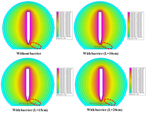
The potential distributions for both the baseline scenario (without barrier) and the different widths of barrier are shown in Figure 3. The effect of the width of barrier has a significant effect on how the potential distribution is changed. As width increases along the horizontal axis (L), the electric field distribution and potential contours change. Wider barriers create a greater degree of distortion in electric field lines, resulting in areas where locally there are higher or lower potentials. This distortion to the field lines changes how the overall potential gradient is affected, subsequently influencing the magnitude and direction of the electric field as well.
Figure 3. Electric potential distribution without and with barrier for different width (L) of the barrier
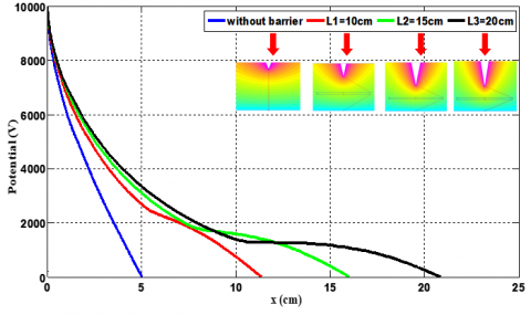
Electric potential varies with respect to distance between a point and plane (point-plane configuration) in Figure 4, both with and without various widths of barriers prohibiting electric field motion. If the barrier has a small, then the electric field has less difficulty moving around the barrier, so the distribution of potential is less distorted. However, if the width of the barrier becomes larger, it provides a more significant impediment to the electric field and causes the electric field lines to bend more sharply around the barrier which results in increased distortion in the potential distribution. The distortion in the electric potential may move the high-potential areas significantly or they may remain in their original locations, but if there is a concentration of high-potential, there will be areas with very high potential shielding and/or areas with high potential concentration, depending on the geometry of the barrier and its material properties. Overall, the barrier width is a very important parameter in determining the electrostatic environment of the system. Therefore, the barrier width has a direct effect on the amount of potential and the location of potential throughout the entire system.
Figure 4. Variation of electric potential as a function of gap spacing in the point-plane gap without and with barrier for different widths (L) of the barrier
3.3 Field of the point-plane gap with and without a dielectric barrier for different widths (L) of the barrier
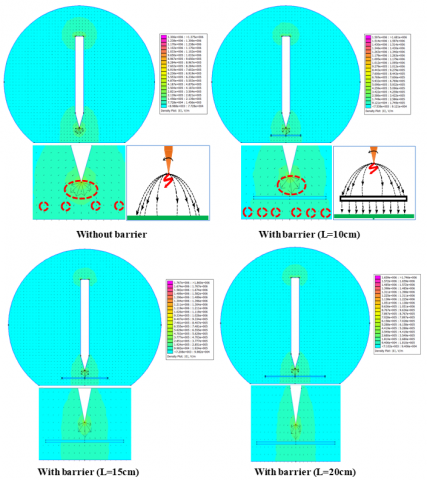
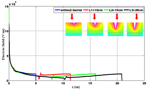
Figures 5 and 6, respectively show the Electric field distribution without and with barrier for different widths (L) of the barrier, as well as the variation of electric field as a function of gap spacing in the point-plane gap without and with barrier for different widths (L) of the barrier.
Figure 5. Electric field distribution without and with barrier for different widths (L) of the barrier
Figure 6. Variation of the electric field as a function of gap spacing in the point-plane gap without and with barrier for different widths (L) of the barrier
•The influence of the electric field in a point-plane gap is significantly impacted by the presence of a dielectric barrier and its width (L).
•In the absence of a dielectric barrier, the electric field lines originate from the point and spread uniformly towards the plane. The field intensity is highest near the point and decreases as it approaches the plane. This configuration results in a predictable and symmetric distribution of the electric field.
•Introducing a dielectric barrier into the point-plane gap alters the electric field distribution. The dielectric material distorts the electric field lines, typically reducing the field intensity within the dielectric due to its insulating properties. The degree of this distortion depends on the width of the barrier.
•With a narrow barrier, the electric field is slightly disturbed, causing a modest redistribution of the field lines. The field may partially bypass the barrier, leading to localized changes in field intensity near the edges of the barrier.
•As the width of the barrier (L) increases, the distortion becomes more pronounced. The electric field lines are forced to diverge more significantly around the barrier, leading to a decrease in field intensity within and immediately around the barrier. This can create regions of lower field strength or even shielding effects, depending on the barrier's material properties.
•The presence and width of the dielectric barrier play a crucial role in shaping the electric field within the point-plane gap, with wider barriers exerting a more significant influence on the field's distribution and intensity. The barrier creates a uniform field zone between itself and the plane, effectively dividing the needle-plane system into two subsystems: one between the needle and the barrier, and the other between the barrier and the plane. The latter behaves as a plane-plane system, which is the most rigid. Our results align with findings from other researchers [1, 21].
•The vectors shown in Figure 5 are tangent to the electric field lines, indicating that the electric field is stronger on the side nearer to the pointed electrodes.
The magnitude and direction of the electric field have considerably changed from the original conditions established by the tip of the needle. The highest electric field intensity that used to be concentrated at the tip of the electrode has been decreased, and therefore, this field becomes redistributed. The increased distance between barrier endpoints has resulted in a much larger uniform electric field strength, where the field strength between the two electrodes is now at a reduced level of strength.
The current work shows numerically modeled by the FEM how varying the dielectric barrier's width has an effect on the electrostatic field and potential distributions in a point plane configuration operating under AC voltage. The simulations indicate that the dielectric barrier's width has a significant effect on the electrostatic field distribution compared to the case with no barrier. When there was no barrier present, there was an expected, and predictable, but non-uniform electric field with maximum electric field strength at the point electrode.
The addition of a dielectric barrier changes the electric field strength being used; this is accomplished by changing the direction of the electric field lines. It has also been shown that the amount of change in the direction of the electric field lines will be dependent on how wide the dielectric barrier is:
•When the dielectric barrier is very narrow, it will have a very small effect on the arrangement of the electric field lines, and there is a chance that some electrical field lines may pass around the barrier.
•As the width of the dielectric barrier increases, the degree and amount of change in the arrangement of the electric field lines also become greater. The dielectric barrier now becomes a larger obstacle for the electric field lines and forces them to curve around the barrier, thereby reducing the intensity of the electric field at the point electrode, while at the same time producing a more even distribution of the electric field across the gap between the dielectric barrier and the planar surface.
The width of the dielectric barrier is therefore an important design consideration for a designer who is attempting to control and provide a uniform electric field in point-plane devices, where this can improve the dielectric strength of the materials involved.
For future work, the following recommendations can be made:
•Investigate the effects of various dielectric materials on the electric field distribution to understand how different properties, such as permittivity and conductivity, influence the results.
•Extend the study to include barriers with non-uniform shapes, such as tapered or curved barriers, to assess how these geometries impact the electric field distribution.
•Study configurations with multiple barriers to determine how the interaction between barriers affects the electric field and potential distribution.
[1] Nessark, F., Benguesmia H., Bakri, B. (2024). Numerical study of dielectric strength in point-plane air gaps with barrier and their effect on the potential and electric field under AC voltage. NeuroQuantology, 22(2): 211-219. https://doi.org/10.48047/nq.2024.22.2.NQ24023
[2] Chankuson, P., Chumsri, P., Plodkaew, A. (2023). The Simulation of dielectric barrier discharge for breakdown voltage in starch modification. Applied Sciences, 13(22): 12143. https://doi.org/10.3390/app13221214
[3] Guo, Z., Gou, Q., Yang, L., Yu, Q.L., Han, L. (2022). Dielectric barrier discharge plasma: A green method to change structure of potato starch and improve physicochemical properties of potato starch films. Food Chemistry, 370: 130992. https://doi.org/10.1016/j.foodchem.2021.130992
[4] Guerbas, F., Zitouni, M., Boubakeur, A., Beroual, A. (2010). Barrier effect on breakdown of point–plane oil gaps under alternating current voltage. IET Generation, Transmission & Distribution, 4(11): 1245-1250. https://doi.org/10.1049/iet-gtd.2010.0231
[5] Goiana, M.L., Mattos, A.L.A., de Azeredo, H.M.C., de Freitas Rosa, M., Fernandes, F.A.N. (2022). Influence of dielectric barrier discharge cold plasma treatment on starch, gelatin, and bacterial cellulose biodegradable polymeric films. Polymers, 14(23): 5215. https://doi.org/10.3390/polym14235215
[6] Abdel-Salam, M., Weiss, P., Lieske, B. (2002). Discharges in air from point electrodes in the presence of dielectric plates-Experimental results. IEEE Transactions on Electrical Insulation, 27(2): 309-319. https://doi.org/10.1109/14.135602
[7] Park, J., Cha, M.S. (2025) Measuring space charge and electric field in axisymmetric dielectric barrier discharge using EFISH technique. Scentific Reports, 15: 9127. https://doi.org/10.1038/s41598-025-93958-7
[8] Zheng, Y., Li, Q., Chen, Y., Shu, S., Zhuang, C. (2019). Breakdown path and condition of air-insulated rod–plane gap with polymeric barrier inserted under alternating voltages. AIP Advances, 9(10): 105207.10.1063/1.5119169
[9] Ren, Y., Cui, W., Pitsch, H., Li, S. (2020). Experimental and numerical studies on electric field distribution of a premixed stagnation flame under DC power supply. Combustion and Flame, 215: 103-112. https://doi.org/10.1016/j.combustflame.2020.01.028
[10] Zhang, S., Wang, W.C., Yang, D.Z., Yuan, H., Zhao, Z.L., Sun, H., Shao, T. (2019). Nanosecond pulsed uniform dielectric barrier discharge in atmospheric air: A brief spectroscopic analysis. Spectrochimica Acta Part A: Molecular and Biomolecular Spectroscopy, 207: 294-300. https://doi.org/10.1016/j.saa.2018.09.004
[11] Zheng, Y., Zhang, P., Wang, Y., He, T. (2022). Breakdown path control by barrier effect for improving withstand characteristics of air-insulated gaps under alternating voltages. High Voltage, 7(4): 753-762. https://doi.org/10.1049/hve2.12183
[12] Benziada, M.A., Boubakeur, A., Mekhaldi, A. (2018). Numerical simulation of the electric field distribution in point-barrier-plane air gaps. IEEE Transactions on Dielectrics and Electrical Insulation, 25(6): 2093-2102. https://doi.org/10.1109/TDEI.2018.007160
[13] Talaat, M. (2014). Electrostatic field calculation in air gaps with a transverse layer of dielectric barrier. Journal of Electrostatics, 72(5): 422-427. https://doi.org/10.1016/j.elstat.2014.07.003
[14] Foruzan, E., Akmal, A.A., Niayesh, K., Lin, J., Sharma, D.D. (2018). Comparative study on various dielectric barriers and their effect on breakdown voltage. High Voltage, 3(1): 51-59. https://doi.org/10.1049/hve.2017.0032
[15] Yang, Z., Lv, L., Wang, H., Wang, Y., Liu, J., Li, H. Li, X. (2025). Simulation study on the electric field of three-phase three-post insulators under typical defects. Energies, 18(9): 2344. https://doi.org/10.3390/en18092344
[16] Talaat, M., Essa, M.A. (2019), Effect of electrohydrodynamic stresses in dielectric liquid: simulation study with the aid of single artificial air bubble using level set-volume of fluid method. IET Generation, Transmission and Distribution, 13: 4694-4701. https://doi.org/10.1049/iet-gtd.2018.6926
[17] Abd Alameer, M., Khalaf, T. (2020). Computational analysis for electrical breakdown in air due to streamer discharge in rod-to-plane arrangement. IOP Conference Series: Materials Science and Engineering, 757: 012018 https://doi.org/10.1088/1757-899X/757/1/012018
[18] Dong, G., Li, Q., Liu, T., Gao, H., Zhang, M. (2020), Finite-element analysis for surface discharge on polyimide insulation in air at atmospheric pressure under pulsed electrical stress. High Voltage, 5: 166-175. https://doi.org/10.1049/hve.2019.0242
[19] Ghermoul, O., Benguesmia, H., Benyettou, L. (2023). Finite element modeling for electric field and voltage distribution along the cap and pin insulators under pollution. Diagnostyka, 24(2): 2023201. https://doi.org/10.29354/diag/159517
[20] Sianturi, F.A., Ernidawati, T. (2025). Analysis of electric potential distribution in a system without charge using laplace's equation approach; literature review. Journal of Frontier Research in Science and Engineering (JoFRISE), 3(1): 20-25.
[21] Kang, W.S., Park, J.M., Kim, Y., Hong, S.H. (2003). Numerical study on influences of barrier arrangements on dielectric barrier discharge characteristics. IEEE Transactions on Plasma Science, 31(4): 504-510. https://doi.org/10.1109/TPS.2003.815469