Cossu Michele*![]() | Morselli Nicolò
| Morselli Nicolò![]() | Marco Puglia
| Marco Puglia![]() | Muscio Alberto
| Muscio Alberto![]()
© 2025 The authors. This article is published by IIETA and is licensed under the CC BY 4.0 license (http://creativecommons.org/licenses/by/4.0/).
OPEN ACCESS
The electrification of transportation is rapidly transforming public mobility, yet battery-electric vehicles still face significant range limitations. In this context, hydrogen fuel cell systems emerge as a promising alternative, capable of extending vehicle range while reducing environmental impact. However, thermal management remains a critical challenge, as passenger cabin cooling and the regulation of fuel cell and battery temperatures consume a substantial portion of the vehicle's available energy. This study explores the use of an evaporative cooling system based on the Maisotsenko cycle to cool the passenger cabin of a fuel cell bus while also contributing to powertrain thermal management through the reuse of exhaust airflow. In the proposed configuration, the primary airflow from the evaporative cycle is directed toward cabin ventilation and cooling, whereas the working exhaust air is utilized for the thermal regulation of the fuel cell and battery system. Additionally, the water produced as a byproduct of the hydrogen-oxygen reaction in the fuel cell is recovered and used to sustain the evaporative cooling process, creating an integrated system that reduces dependence on external resources and minimizes overall energy consumption. The system's performance was evaluated in terms of cooling capacity, water balance, and thermal efficiency under various environmental conditions. Results indicate that this synergistic approach can significantly enhance the energy efficiency of hydrogen fuel cell electric buses, providing an innovative and sustainable solution for urban mobility.
urban bus, cooling, M-cycle
The transportation sector is undergoing a profound transformation, driven by the urgent need to reduce greenhouse gas and pollutant emissions. Electric vehicles are steadily increasing their market share, but their large-scale adoption is hindered by several critical issues: limited driving range and still-lengthy charging times [1]. Urban public transport is not immune to these challenges: while it contributes significantly to lowering climate-altering emissions compared to private cars, it remains a substantial source of noise and harmful gases in metropolitan areas [2].
A promising alternative for heavy-duty service vehicles is offered by hydrogen fuel cells, electrochemical devices that convert the chemical energy of hydrogen into electrical energy through redox reactions. Among various technologies, the Proton Exchange Membrane Fuel Cell (PEMFC) stands out for automotive applications thanks to its low operating temperature (60–80℃), rapid start-up, reduced noise and high power density [3]. Although infrastructure development and higher costs compared to full-electric vehicles currently limit fuel cell competitiveness, their short refueling times and extended driving ranges make hydrogen buses an attractive solution for high-load routes and long distances [4].
However, the operational range of electric buses depends not only on traction but is significantly influenced by the energy demand of HVAC systems [5]. In an urban electric bus, summer air conditioning can consume over 20% of the average power delivered by the traction system [6], noticeably reducing maximum range.
For this reason, the present study investigates the use of evaporative cooling (EC) systems for thermal management of an urban bus cabin. EC systems are well known to be less energy-intensive than conventional vapor-compression units, since they exploit the conversion of sensible heat into latent heat via water evaporation, without the need for a compressor [7]. By operating exclusively with outdoor air, they also ensure continuous air exchange within the cabin—crucial to mitigate the transmission risk of airborne pathogens in crowded environments like buses [8].
Among the various indirect evaporative cooling (IEC) cycles, the Maisotsenko cycle (M-cycle) is distinguished by its exceptional energy efficiency. This dew-point evaporative cooling (DPEC) cycle recirculates a portion of the pre-cooled air into the wet channel of the heat-and-mass exchanger, thereby enhancing overall heat-exchange effectiveness. Thanks to this strategy, wet-bulb effectiveness can exceed 100% by setting the dew point as the lower temperature limit [9].
Finally, since evaporative systems require water to operate, integration with hydrogen fuel cells—which produce water as a byproduct—becomes particularly advantageous. Utilizing the PEMFC exhaust water to feed the EC circuit can reduce onboard freshwater consumption and valorize the propulsion system’s “waste.”
The objective of this work is therefore to evaluate the integration of the Maisotsenko cycle in an urban bus, with the aims of:
In doing so, the study seeks to enhance the vehicle’s overall sustainability and extend its operational range.
This study aims to analyze the thermal behavior of a standard 12-meter urban bus under steady-state or quasi-steady-state conditions, using a numerical energy balance model.
The reference vehicle is a 12 meter long urban bus with a maximum transport capacity of approximately 88 passengers, of whom 26 are seated. This configuration may vary based on the internal layout and the number of wheelchair spaces. The main dimensions of the external envelope and maximum occupancy data are summarized in Table 1.
For estimating internal heat loads due to occupants, reference is made to the UNI EN ISO 8996:2022 standard [10], which classifies metabolic load based on activity. A load of 125 W per seated person and 180 W per standing person (average value for light activity) is considered. With 26 seated individuals and 62 standing individuals, plus the driver (also assimilated to 180 W), the maximum internal heat load due to occupancy is estimated at 14.59 kW. As a simplifying assumption for this analysis, these heat gains are considered entirely convective and released into the internal air of the passenger cabin (Φconv,in).
Table 1. Urban bus dimensions
|
Parameters |
Values |
|
|
Vehicle length |
12.135 |
m |
|
Vehicle width |
2.55 |
m |
|
Floor height from ground level |
0.28 |
m |
|
Roof height from ground level |
3.0 |
m |
The bus geometry, including the dimensions and positioning of windows and doors, was derived from technical drawings and specifications provided by various manufacturers. A portion of the rear volume of the bus is designated for the engine compartment; this region is treated as a separate thermal zone at an imposed temperature. The separation surfaces between the engine compartment and the passenger cabin are treated without solar gains.
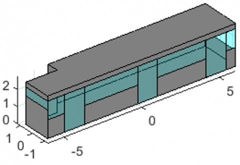
The heat balance model was implemented in the MATLAB environment. The bus envelope and the internal environment (passenger cabin) are discretized into Np planar surfaces, each with specific thermophysical and optical properties. The geometry of the bus cabin is shown in Figure 1. The primary unknowns of the model, totaling 2Np+1, are:
The model solves the system of energy balance equations at the internal and external surfaces of the envelope and for the internal air volume.
Figure 1. Bus cabin model
This calculation constitutes a first approach to the problem, aiming to determine equilibrium conditions under severe operating loads without accounting for dynamic effects arising from the thermal capacitance of walls and components within the cabin. Consequently, as a simplifying assumption, conductive heat transfer through the j-th envelope element is modeled using Fourier’s law for one-dimensional, steady-state conduction. The conductive heat flux density, qcond,j, is expressed as
$q_{\text {cond }, i}=U_{\text {cond }, i}\left(T_{s, i n, i}-T_{s, o u t, i}\right)$ (1)
where, Ucond,j is the thermal transmittance of the j-th element.
The convective heat flux between the internal air and the internal surface j, qconv,in,j, is calculated as
$q_{\text {conv}, i n, j}=h_{\text {conv}, i n, j}\left(T_{i n, j}-T_{s, i n, j}\right)$ (2)
Similarly, the convective heat flux between the external surface j and the external environment, qconv,out,j, is
$q_{\text {conv}, \text {out}, j}=h_{\text {conv}, \text {out}, j}\left(T_{\text {out}, j}-T_{\text {s,out}, j}\right)$ (3)
where, hconv,in,j and hconv,out,j are the internal and external surface convective heat transfer coefficients, respectively.
The solar irradiance incident on the external surfaces is broken down into direct (Isol,dir,j), diffuse (Isol,dif,j), and reflected (Isol,rif,j) components from the ground [11].
The solar heat flux density absorbed by the external surface j, qsol,abs,out,j, is
$q_{\text {sol,out}, i}=\alpha_{\text {out}, i}\left(I_{\text {sol,dir}, i}+I_{\text {sol,dif}, i}+I_{\text {sol,rif}, i}\right)$ (4)
where, αout,j is the solar absorptance of the external surface j.
The solar heat flux density transmitted inwards through transparent elements j, qsol,transm,j, is
$q_{\text {sol,transm}, j}=\tau_j\left(I_{\text {sol,dir}, j}+I_{\text {sol,dif, } j}+I_{\text {sol,rif, } j}\right)$ (5)
where, τj is the solar transmittance of element j. The total incoming solar heat flux into the environment, Φsol, is
$\Phi_{\text {sol }}=\sum_{i=1}^{N_p} A_j q_{\text {sol,transm}, j}$ (6)
where, Aj is the area of surface.
In this study, it is assumed that the solar flux transmitted through the glazing, Φsol, is entirely transferred to the internal air.
The net long-wave radiative exchange for the external surface j, qlr,out,j, with the sky is linearized. For surfaces exposed to the sky, the model follows the calculation methods outlined in the UNI EN ISO 52017 [12] standard.
$h_{l r, o u t, j}=4 \varepsilon_{o u t, j} \sigma\left(\frac{T_{o u t}+T_{s, o u t, j}}{2}\right)^3$ (7)
$q_{s k y, j}=F_{s k y, j} 4 \varepsilon_{o u t, j} \sigma\left(\frac{T_{o u t}+T_{s k y}}{2}\right)^3\left(T_{o u t}-T_{s k y}\right)$ (8)
$q_{\text {lr,out }, i}=h_{\text {lr,out}, i}\left(T_{\text {out}}-T_{\text {s,out}, i}\right)-q_{\text {skv, } i}$ (9)
where, εout,j is the infrared emissivity of the external surface j, σ is the Stefan-Boltzmann constant (5.670 × 10⁻⁸ W·m-2·K-4), Fsky,j is the view factor between surface j and the sky vault and Tsky is the apparent sky temperature calculated as [13]
$T_{\text {sky }}\left[{ }^{\circ} \mathrm{C}\right]=18-51.6 e^{-p_{v, \text { out } / 1000}}$ (10)
The long-wave radiative exchange between the Np internal surfaces is determined using the radiosity method, assuming grey and diffuse surfaces. The emittance of surface j, Ej, is
$E_j=\varepsilon_{i n, j} \sigma T_{s, i n, j}^4$ (11)
where, εint,j is the infrared emissivity of the internal surface j. The system of equations for the radiosities Jj, representing the total radiant flux leaving surface j, is
$\sum_{k=1}^{N_p}\left[\delta_{j k}-\gamma_j F_{j k}\right] J_k=E_j$, for $\mathrm{j}=1, \ldots, \mathrm{~N}_{\mathrm{p}}$ (12)
where, δik is the Kronecker delta, γj is the reflectivity of the surface and Fjk is the view factor between surface j and k. By solving this linear system, the radiosity values Jj are obtained. The net long-wave radiative heat flux absorbed by surface j, qlr,in,j, is then calculated as the difference between the irradiation received Gj and the radiosity Jj
$G_j=\sum_{k=1}^{N_p} F_{j k} J_k$ (13)
$q_{l r, i n, j}=G_j-J_j$ (14)
For the study of the evaporative cooling system, the entire cooling capacity is attributed to the incoming airflow, which is supplied at a temperature lower than the internal cabin temperature. Consequently, the total cooling effect is incorporated within the sensible heat flux component associated with ventilation ΦV.
$\Phi_V=\dot{m}\left(c_{p, m a, e n} T_{e n}-c_{p, m a, e x} T_{e x}\right)$ (15)
For the analysis of the M-cycle heat and mass exchanger, a simplified one-dimensional numerical algorithm is implemented. This algorithm iteratively evaluates the local heat and mass balance between the dry and wet channels of the exchanger. The following simplifying assumptions are made:
At each discretization step along the length of the channels, a non-linear system of energy and mass balance equations is solved. This system couples the dry channels, where only sensible heat exchange, qsen,d, occurs, with the wet channels, where simultaneous sensible, qsen,w, and latent, qlat,w, heat exchanges (due to water evaporation from the wetted surfaces) take place.
The energy balance for a differential control volume in the dry channel is expressed as
$m_{d a, d} c_{p, m d} d T_d=-d q_{s e n, d}=-U_{i \leftarrow d}\left(T_d-T_i\right) d A$ (16)
where, mda,d is the mass flow rate of dry air in the dry channel, cp,md is the specific heat capacity of moist air at constant pressure, Uid is the overall heat transfer coefficient from the dry channel to the water interface, Td and Ti are the temperatures in the dry channel and in the interface, respectively, and dA is the differential exchange surface. For the wet channel, the corresponding energy balance equation is
$m_{d a, w} d i_w=-\left(d q_{s e n, w}+d q_{l a t, w}\right)$ (17)
With mda,w the mass flow rate of dry air in the wet channel and iw the specific enthalpy of humid air. Here, the sensible and latent heat contributions are further described by constitutive relations involving heat and mass transfer coefficients. The sensible heat exchange between the water interface and the wet channel air stream is governed by Newton’s law of cooling
$q_{\text {sen }, w}=h_{\text {conv }, w}\left(T_i-T_w\right) d A$ (18)
where, hconv,w is the convective heat transfer coefficient in the wet channel and Tw is the temperature in the wet channel. The latent heat exchange in the wet channel is driven by the difference in vapor mass density, ρv, between the saturated air at the water interface and the bulk air in the wet channel
$d q_{l a t, w}=d m_e i_{v i}=h_{m a s s, w}\left(\rho_{v, i}-\rho_{v, w}\right) i_{v i} d A$ (19)
With me indicating the evaporated mass flow rate. Finally, the energy balance for the water film coating the surfaces of the wet channel—assumed to be static and at a uniform temperature Tf at each cross-section — is obtained by imposing the equality of enthalpy variations across the dry and wet sides. This final relation represents the thermal equilibrium at the water film interface, accounting for convective and evaporative heat exchange with the wet air stream and conductive/convective heat transfer from the dry side through the separating wall.
By solving the resulting system of equations for the unknowns Td, Tw, Tf, and ρvw at each discretization step, the model yields the profiles of the bulk air temperatures in both dry and wet channels, the temperature profile of the static water film, and the evolution of the absolute humidity in the wet channel. The latter provides the quantity of water evaporated during the process.
At this point, all heat flows to perform the steady state analysis have been defined. For each internal surface j, the energy balance requires the sum of fluxes to be zero
$q_{c o n v, i n, j}+q_{s o l, i n, j}+q_{l r, i n, j}-q_{c o n d, j}=0$ (20)
Similarly, for each external surface j, the balance is
$q_{\text {conv}, \text {out}, j}+q_{\text {sol,out}, j}+q_{\text {lr,out}, j}+q_{\text {cond}, j}=0$ (21)
The energy balance for the internal air volume of the cabin is
$\sum_{j=1}^{N_p}\left(-A_j q_{\text {conv}, i n, j}\right)+\Phi_V+\Phi_{\text {sol }}+\Phi_{\text {conv}, i n}=0$ (22)
where, Σ(-Aj⋅qconv,in,j) is the total convective heat flux exchanged with the internal surfaces. The energy balance equations—one for the indoor environment, Np for the internal surfaces, and Np for the external surfaces—thus form a system of 2Np+1 algebraic equations in 2Np+1 unknowns (Tint, Ts,int,j, Ts,est,j) Once solved, this system provides insight into the thermal conditions of the urban bus envelope under the analyzed conditions.
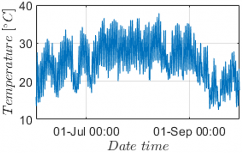
For this study, the city of Modena (Italy) was selected as the reference location for the analysis. To identify the most critical condition for evaluating the performance of the M-cycle as a summer cooling system, a preliminary assessment was conducted by calculating the absorbed and transmitted solar power over the period from July 1st to August 31st. This time window was chosen based on local meteorological data, which indicate that air temperatures commonly exceed 30℃ during this interval, as shown in Figure 2.
Figure 2. Air temperatures recorded in Modena between June 1 and September 30, 2024
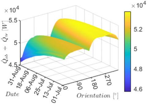
Figure 3. Daily peak values of the sum of absorbed and transmitted solar power for each bus orientation during the period from July 1 to August 31
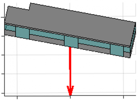
Figure 4. Perspective view from the direction of solar rays incident on the bus cabin at the critical time (August 3, 12:27 PM) and orientation (258°), corresponding to the highest combined absorbed and transmitted solar power during the selected period
For each time step within the selected period, the bus envelope was virtually oriented at all azimuth angles (1° to 359°). The maximum daily values of the sum of absorbed and transmitted solar power were calculated and are illustrated in Figure 3. The peak combined solar load occurred on August 3rd at 12:27 PM (solar time), when the bus was oriented at an azimuth angle of 258°. Figure 4 shows the bus cabin under the identified critical solar exposure, indicating the direction of the incident solar radiation.
The configuration of the M-cycle system analyzed in this study consists of a parallel-plate arrangement, comprising alternating wet and dry channels, each with a height of 5 mm and a width of 30 cm. Three channel lengths were considered: 1 m, 1.5 m, and 2 m. A constant air velocity of 2.4 m/s was assumed in the dry channels to ensure steady-state flow conditions. The wet to dry channel mass flow rate was set to 0.33.
Assuming a vertical arrangement of the heat exchange surfaces, the system was modeled with 200 dry channels and 201 wet channels, separated by 0.5 mm thick walls. This configuration ensured that the total width of the heat exchanger remained within the available rooftop space of the bus (2.55 m). The main parameters of the modeled M-cycle system are summarized in Table 2.
Table 2. M-cycle parameters
|
Parameters |
Values |
|
|
Dry channel height |
5 |
mm |
|
Wet channel height |
5 |
mm |
|
HMX width |
0.3 |
m |
|
HMX lenght |
1-1.5-2 |
m |
|
Number of dry channels |
200 |
|
|
Number of wet channels |
201 |
|
|
Wall thickness |
0.5 |
mm |
|
Dry channels air velocity |
2.4 |
m. s-1 |
|
Working to inlet mass flow rate |
0.33 |
|
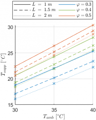
As previously described, the solar loads were computed based on the specific time instant and bus orientation. For the external thermohygrometric conditions, multiple scenarios were considered, with air temperatures of 30℃, 35℃, and 40℃, and relative humidities of 30%, 40%, and 50%. The resulting outlet temperatures of the M-cycle under these conditions are presented in Figure 5.
Figure 5. M-cycle outlet air temperature under varying ambient temperature, relative humidity, and exchanger length conditions
The results show that, for fixed geometry, the outlet air temperature from the M-cycle system is strongly influenced by the inlet ambient temperature and relative humidity. External ambient air is drawn directly into the cooling system, where it is conditioned before being supplied to the cabin. As a result, the incoming ventilation air enters the vehicle at a lower temperature, effectively reducing the heat gains associated with ventilation.
With a heat exchanger length of 1 m, an outlet air temperature of 18.7℃ is achieved under ambient conditions of 30℃ and 30% relative humidity (RH). Under the same RH but with an increased ambient temperature of 40℃, the outlet temperature rises to 25.3℃. The resulting temperature drops across the system are 11.3℃ and 14.7℃, respectively. Increasing the length of the HMX leads to further reductions in outlet temperature, though with a nonlinear trend. For example, at a length of 2 m, the outlet air temperature decreases to 16.1℃ for ambient conditions of 30℃ and 30% RH, and to 22.2℃ for 40℃ and 30% RH.
Under ambient RH of 30%, the M-cycle system consistently delivers outlet air temperatures below the summer comfort threshold of 26 ± 1℃ across all the temperature scenarios considered. This makes the system particularly effective in ensuring air exchange while simultaneously assisting in the removal of internal heat gains from the cabin.
As expected for evaporative cooling systems, the performance of the M-cycle decreases as ambient humidity rises. Under the most unfavorable condition considered — 50% RH and a 1 m heat exchanger — the outlet air temperature remains below the summer comfort limit up to an ambient temperature of 35℃. At 40℃ ambient, however, the outlet temperature rises to 30.4℃. The corresponding inlet-to-outlet temperature reductions are 7.6℃ at 30℃ ambient and 9.6℃ at 40℃.
Extending the heat exchanger length to 2 m allows the system to maintain outlet temperatures below the comfort threshold up to an ambient temperature of approximately 37℃, even at 50% RH.
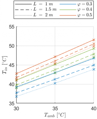
Given the assumed recirculation ratio of 0.33, the mass flow rate of the ventilation air is 67% of the total ambient air processed by the HMX. To ensure adequate indoor air quality — specifically, maintaining CO₂ levels below 1000 ppm — a minimum ventilation rate of approximately 7 L·s⁻¹ per person is required. Based on the current configuration, at least two HMX units must be installed to achieve a ventilation airflow that exceeds this minimum requirement.
Figure 6. Equilibrium cabin temperature with two M-cycle units as a function of the analyzed parameters
The results obtained are presented in Figure 6. In this configuration, it is observed that, across all conditions analyzed, the resulting equilibrium cabin temperatures significantly exceed the upper limit for thermal comfort.
Even under the most favorable ambient condition for evaporative systems — 30% relative humidity — the internal equilibrium temperatures reach 39.2℃ and 46.7℃ for outdoor air temperatures of 30℃ and 40℃, respectively, when using 1 m long HMX units. Increasing the HMX length to 2 m lowers the equilibrium cabin temperatures to 36.8℃ and 43.9℃ for the same external conditions. These values remain well above the acceptable range for summer indoor comfort, highlighting that evaporative cooling alone is insufficient for maintaining thermal comfort in the cabin.
Specifically, relying solely on the M-cycle cooling system with an airflow rate slightly above the minimum required to maintain indoor CO₂ levels below 1000 ppm proves largely inadequate for conditioning an occupied bus cabin. Under 50% ambient RH and 2 m long HMX units, internal equilibrium temperatures reach 41℃at 30℃ ambient and peak at 50℃ when ambient temperature rises to 40℃.
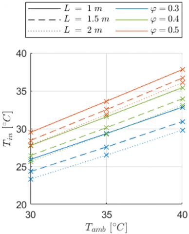
A separate analysis considering six M-cycle units (Figure 7) shows that, under low ambient humidity conditions (30% RH), 1 m long exchangers are sufficient to achieve an equilibrium cabin temperature of 26℃ at 30℃ ambient. With 2 m long exchangers, this threshold is maintained even beyond an ambient temperature of 34℃. However, under higher humidity levels, an internal equilibrium temperature below 26℃ can only be achieved under specific conditions — namely, 40% RH, 2 m-long exchangers, and 30℃ ambient temperature. All other high-humidity scenarios fail to ensure acceptable thermal comfort.
Figure 7. Equilibrium cabin temperature with six M-cycle units as a function of the analyzed parameters
It is worth noting that implementing six 2 m long M-cycle units would occupy the entire roof area of the bus, which may pose practical limitations due to weight and cost constraints.
These findings suggest that, under the most severe operating conditions expected for an urban bus in Modena — typically midday during July or August with full passenger occupancy — the M-cycle evaporative cooling system alone is insufficient to ensure thermal comfort.
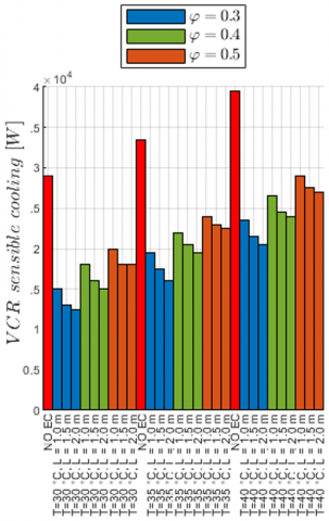
In any case, a vapor compression refrigeration (VCR) system must be installed in urban buses to ensure winter heating, making it inherently available for potential use in summer cooling as well. When considering cooling provided exclusively by a VCR system with no ventilation air, approximately 24 kW of sensible cooling capacity is required to maintain an internal temperature within the comfort range (26 ± 1℃) at 30℃ ambient, increasing to about 25 kW at 40 °C ambient. If outdoor air is introduced at ambient temperature to provide ventilation equivalent to that of two M-cycle banks, the required VCR cooling capacity rises to 29 kW at 30℃ ambient and 39.5 kW at 40℃.
Given the necessity of providing fresh air to maintain indoor air quality, a hybrid cooling strategy was also evaluated. This approach combines a VCR system with two M-cycle units to ensure the required ventilation and guarantee the internal equilibrium temperature in the range 26 ± 1℃. The results of the hybrid VCR/M-cycle configuration are shown in Figure 8. These results clearly demonstrate that integrating just two M-cycle units into the ventilation system significantly reduces the sensible cooling capacity required from the VCR to maintain the target indoor temperature.
Under the most favorable scenario — ambient temperature of 30℃, relative humidity of 30%, and 2 m long HMX units — the VCR cooling demand is reduced by more than 50%. Even in the most challenging condition considered — 40℃ ambient temperature, 50% relative humidity, and 1 m long HMX units — the reduction remains substantial at approximately 27%.
As expected, the cooling contribution of the M-cycle diminishes with increasing ambient humidity and temperature, due to the reduced potential for evaporative cooling. Nonetheless, the decrease in required VCR sensible cooling capacity remains significant across all tested scenarios, highlighting the robustness of the hybrid strategy even under adverse environmental conditions.
Figure 8. Required VCR sensible cooling capacity under various environmental conditions to maintain an internal equilibrium temperature within the comfort range of 26 ± 1℃ using a hybrid M-cycle/VCR system
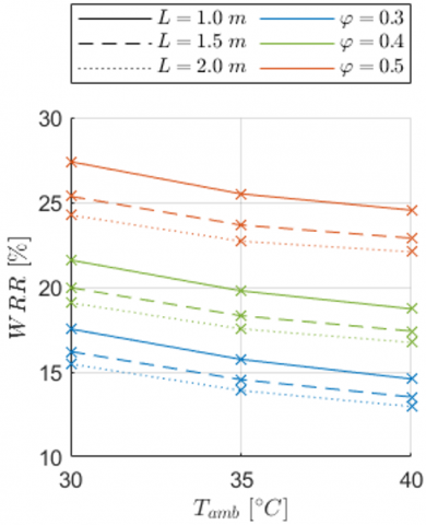
Figure 9. Water recovery ratio (WRR) for a fuel cell-powered urban bus equipped with two M-cycle units, evaluated under varying ambient temperatures, relative humidity levels, and HMX lengths
Additionally, the length of the HMX units emerges as another key design parameter to consider. Increasing the exchanger length leads to lower outlet air temperatures from the M-cycle units, thereby enhancing the support provided to the VCR system and reducing its sensible cooling demand. However, the incremental benefits diminish progressively with longer HMX, as performance gains become less pronounced. This trend underscores the importance of identifying an optimal configuration that balances the reduced energy demand of the VCR system with the increased energy consumption, volume, and cost associated with larger M-cycle units.
Based on the water consumption of the M-cycle system under the various operating conditions and exchanger lengths analyzed, a final evaluation was conducted to assess the feasibility of this system when applied to a fuel cell-powered urban bus. Assuming the use of two M-cycle units to support the VCR system, an estimate of onboard water availability can be derived using data from literature. Specifically, for a fuel cell operating at 1.5 bar and with a water recovery temperature of 60℃ [14], it is possible to calculate the water recovery ratio (WRR), defined as the ratio between the water recovered from the fuel cell and the water required by the evaporative cooling system.
The results of this analysis are presented in Figure 9. As shown, the highest water recovery ratios are achieved under high ambient humidity conditions. The maximum WRR reaches 27.4% for an ambient relative humidity of 50%, an ambient temperature of 30℃, and HMX units with a length of 1 m. As expected, increasing the length of the HMX units leads to a higher water demand by the evaporative system, due to the increased surface area available for evaporation. Conversely, increasing the ambient temperature while maintaining constant relative humidity results in a slight decrease in the fraction of water that can be reused.
The lowest WRR observed was 13%, corresponding to 2 m long HMX units operating under ambient conditions of 40℃ and 30% relative humidity.
The results presented in this study highlight the potential of integrating M-cycle evaporative cooling with a vapor compression refrigeration (VCR) system to achieve thermal comfort in fuel cell-powered urban buses during summer operation. However, the implementation of such a hybrid system calls for further optimization and detailed investigation.
In particular, identifying the optimal balance between the number and length of the M-cycle HMX units is crucial. This balance must minimize the energy consumption of both the VCR system and the evaporative units. While longer exchangers improve cooling effectiveness, the diminishing marginal returns with increased HMX length underline the need for a careful trade-off analysis, considering also installation volume and associated costs.
Moreover, the assessment of indoor humidity level is needed. This includes a better understanding of the VCR performance and its potential to recover additional water through condensation, which could further enhance the sustainability of the system by contributing to the water demands of the M-cycle.
The integration of evaporative units on the rooftop of the bus also introduces geometric and thermal implications. Given the significant roof area that would be occupied by the M-cycle system, a more accurate modeling of heat gains through the roof becomes essential to correctly estimate internal thermal loads.
Additionally, improving the thermal performance of the bus envelope remains a key strategy to reduce the overall cooling demand — regardless of the technology adopted. Enhanced insulation and reflective materials can significantly limit external heat gains, thereby reducing reliance on both the cooling systems.
Finally, optimizing the fuel cell exhaust condensation process — specifically, operating at lower recovery temperatures — could substantially increase the amount of condensed water, improving the water recovery ratio (WRR) and supporting the water requirements of the evaporative cooling system.
Altogether, while the proposed hybrid system shows promise, its practical implementation requires a multi-faceted design approach that considers thermal, fluid dynamics, spatial, and operational constraints in an integrated manner.
|
A |
surface area m2 |
|
cp |
specific heat capacity at constant pressure J. kg-1. K-1 |
|
E |
emittance W. m-2 |
|
F |
view factor |
|
h |
heat transfer coefficient W. m-2.K-1 |
|
i |
specific enthalpy of humid air J. kg-1 |
|
I |
solar irradiance W. m-2 |
|
J |
radiosity W. m-2 |
|
m |
mass flow rate kg. s-1 |
|
Np |
number of patches |
|
p |
pressure Pa |
|
q |
heat flow density W. m-2 |
|
T |
temperature K |
|
U |
thermal transmittance W. m-2. K-1 |
|
WRR |
water recovery ratio |
|
Greek symbols |
|
|
a |
absorptivity |
|
γ |
reflectivity |
|
δ |
Kronecker delta |
|
Ε |
emissivity |
|
ρ |
mass density kg. m-3 |
|
σ |
Stefan-Boltzmann constant W. m-2. K-4 |
|
τ |
transmittance |
|
Φ |
heat flow W |
|
Subscripts |
|
|
abs |
absorbed |
|
amb |
ambient |
|
cond |
conductive |
|
conv |
convective |
|
d |
dry channel |
|
da |
dry air |
|
dir |
direct |
|
dif |
diffuse |
|
e |
evaporation |
|
f |
water film |
|
i |
air-water interface |
|
in |
indoor |
|
j |
j-th element |
|
jk |
from surface j to surface k |
|
lat |
latent |
|
lr |
long-wave radiative |
|
m |
moist air |
|
mass |
mass transfer |
|
out |
outdoor |
|
rif |
reflected |
|
s |
surface |
|
sen |
sensible |
|
sky |
sky |
|
sol |
solar |
|
supp |
supplied |
|
transm |
transmitted |
|
v |
vapor |
|
V |
ventilation |
|
w |
wet channel |
[1] Wang, Z., Yu, J., Li, G., Zhuge, C., Chen, A. (2023). Time for hydrogen buses? Dynamic analysis of the Hong Kong bus market. Transportation Research Part D: Transport and Environment, 115: 103602. https://doi.org/10.1016/j.trd.2022.103602
[2] Logan, K.G., Nelson, J.D., Hastings, A. (2020). Electric and hydrogen buses: Shifting from conventionally fuelled cars in the UK. Transportation Research Part D: Transport and Environment, 85: 102350. https://doi.org/10.1016/j.trd.2020.102350
[3] Mench, M.M. (2008). Fuel Cell Engines. John Wiley & Sons.
[4] Ajanovic, A., Haas, R. (2021). Prospects and impediments for hydrogen and fuel cell vehicles in the transport sector. International Journal of Hydrogen Energy, 46(16): 10049–10058. https://doi.org/10.1016/j.ijhydene.2020.03.122
[5] Zacharof, N., Özener, O., Broekaert, S., Özkan, M., Samaras, Z., Fontaras, G. (2023). The impact of bus passenger occupancy, heating ventilation and air conditioning systems on energy consumption and CO2 emissions. Energy, 272: 127155. https://doi.org/10.1016/j.energy.2023.127155
[6] Suh, I.S., Lee, M., Kim, J., Oh, S.T., Won, J.P. (2015). Design and experimental analysis of an efficient HVAC (heating, ventilation, air-conditioning) system on an electric bus with dynamic on-road wireless charging. Energy, 81: 262-273. https://doi.org/10.1016/j.energy.2014.12.038
[7] Duan, Z., Zhan, C., Zhang, X., Mustafa, M., Zhao, X., Alimohammadisagvand, B., Hasan, A. (2012). Indirect evaporative cooling: Past, present and future potentials. Renewable and Sustainable Energy Reviews, 16(9): 6823-6850. https://doi.org/10.1016/j.rser.2012.07.007
[8] Ou, C., Hu, S., Luo, K., Yang, H., Hang, J., Cheng, P., Hai, Z., Xiao, S., Qian, H., Xiao, S., Jing, X., Xie, Z., Ling, H., Liu, L., Gao, L., Deng, Q., Cowling, B.J., Li, Y. (2022). Insufficient ventilation led to a probable long-range airborne transmission of SARS-CoV-2 on two buses. Building and Environment, 207: 108414. https://doi.org/10.1016/j.buildenv.2021.108414
[9] Sadighi Dizaji, H., Hu, E.J., Chen, L. (2018). A comprehensive review of the Maisotsenko-cycle based air conditioning systems. Energy, 156: 725-749. https://doi.org/10.1016/j.energy.2018.05.086
[10] UNI EN ISO 8996:2022, Ergonomics of the Thermal Environment — Determination of Metabolic Rate. https://store.uni.com/uni-en-iso-8996-2022.
[11] Comini, G., Savino, S. (2013). La Captazione dell'Energia Solare. Monografie CISM, International Centre for Mechanical Sciences, Udine, Italy.
[12] UNI EN ISO 52017-1:2018, Prestazione Energetica Degli Edifici - Carichi Termici Sensibili E Latenti E Temperature Interne - Parte 1: Procedure Generali Di Calcolo. https://store.uni.com/uni-en-iso-52017-1-2018.
[13] UNI/TS 11300-1:2014, Prestazioni Energetiche Degli Edifici - Parte 1: Determinazione Del Fabbisogno Di Energia Termica Dell'edificio Per La Climatizzazione Estiva Ed Invernale. https://store.uni.com/uni-ts-11300-1-2014.
[14] Puglia, M., Morselli, N., Cossu, M., Pedrazzi, S., Allesina, G., Muscio, A. (2024). Recovered water from fuel cells as a supply for Maisotsenko evaporative cooling systems in a hydrogen-powered urban bus. Applied Thermal Engineering, 256: 124053. https://doi.org/10.1016/j.applthermaleng.2024.124053