Duy Khanh Tran![]() | The Nhat Nguyen
| The Nhat Nguyen![]() | Anh Tuan Le
| Anh Tuan Le![]() | Nhu Y Do
| Nhu Y Do![]() | Anh Tuan Do*
| Anh Tuan Do*![]()
© 2025 The authors. This article is published by IIETA and is licensed under the CC BY 4.0 license (http://creativecommons.org/licenses/by/4.0/).
OPEN ACCESS
The line-start permanent magnet synchronous motor (LSPMSM) is increasingly applied due to its high efficiency and power factor. However, the electromagnetic parameters of LSPMSMs are strongly influenced by temperature, which leads to significant variations in their operating characteristics. This study focuses on analyzing and evaluating the effects of temperature on the key functional parameters of LSPMSMs, including speed, torque, current, power factor, and efficiency, in order to determine the safe operating temperature range. A mathematical model of the motor, considering temperature-dependent effects, was developed in Matlab & Simulink. The simulation results for a 2.2 kW–1500 rpm LSPMSM show that when the temperature rises from 75℃ to 120℃, the motor exhibits improved starting capability; however, both power factor and efficiency decline with increasing temperature. At 130℃, the LSPMSM fails to maintain stable synchronous operation, with strong oscillations in parameters and a significant reduction in maximum torque and peak current. The findings of this study provide critical insights into defining safe operating limits and serve as a foundation for magnet material selection, cooling design, and real-time monitoring, thereby enhancing the reliability and extending the lifetime of LSPMSMs in industrial applications.
line-start PMSM, temperature effects, thermal modeling, Matlab/Simulink
The Line-Start Permanent Magnet Synchronous Motor (LSPMSM) has emerged as a leading motor technology that bridges the performance gap between traditional squirrel cage induction motors (IMs) and brushless permanent magnet synchronous motors (PMSMs). Combining robust self-starting capability with high steady-state efficiency, LSPMSMs are widely deployed in energy-intensive industrial sectors. However, their operational reliability and efficiency are heavily dependent on thermal behavior, which remains a critical challenge under various load profiles and environmental conditions [1].
Temperature is shown to affect virtually every electrical, magnetic, and mechanical parameter of the motor - ranging from magnet flux density, stator resistance, rotor cage behavior, to dynamic torque characteristics and fault susceptibility. A central concern is the temperature sensitivity of permanent magnets embedded in the rotor. Studies by Baranski et al. [2-3] and Le et al. [4] report that elevated temperature leads to significant degradation of magnetic properties, particularly remanent flux density and coercivity, thereby reducing the air-gap flux and back-EMF amplitude. Thermal demagnetization becomes more pronounced during prolonged start-up or under partial load operations with high slip, leading to torque pulsations, and efficiency losses. Advanced thermal-electromagnetic co-simulations in studies [5-7] quantitatively predict a drop of 10–15% in flux linkage at rotor surface temperatures exceeding 120℃.
Thermal impacts also manifest through increased copper losses in the stator windings. Temperature rise leads to higher resistance (via a positive temperature coefficient), compounding I²R losses. This in turn elevates local winding temperature and may result in hotspot formation. The cascading effect reduces both moto efficiency and insulation lifetime. The study by Palangar et al. [8], models incorporating dynamic loss calculations demonstrate how even moderate ambient temperature changes can produce significant variations in stator temperature and alter the system’s thermal time constant.
Rotor cage dynamics also evolve with temperature. Cage resistance increases, adversely affecting torque production during asynchronous start-up. The studies [9-11] highlight that hybrid rotor configurations (solid rotor + copper/aluminum cage) can mitigate such effects by enhancing heat dissipation and structural robustness. Similarly, thermal analysis of high-voltage LSPMSMs [12, 13] show that the choice of cage geometry and rotor core material dramatically influences rotor heating rate and maximum allowable load cycles.
Additionally, thermal effects are strongly interlinked with fault mechanisms. Temperature accelerates the degradation of insulation materials, increasing the probability of faults such as inter-turn short circuits and rotor bar breakage. The research findings [14-16], FEM-based simulations explore stator asymmetries and rotor eccentricity, which not only increase local losses but also distort magnetic fields, further elevating temperature gradients. Under such conditions, fault diagnosis becomes more challenging without accurate thermal models.
Some studies explore the integration of thermal sensors and real-time monitoring systems to detect performance degradation early. For instance, studies [17, 18] propose embedded thermal models combined with Kalman filtering for rotor temperature estimation, which are vital in sensorless control strategies. Also, the thermal time constants derived in studies [19-21] serve as critical parameters for predictive maintenance and overload protection. From a modeling perspective, it is evident that accurate simulation of LSPMSM behavior requires temperature-dependent parameters in both electromagnetic and thermal domains. Papers [22-25] incorporate nonlinear material models, magnetic hysteresis, and thermal boundary conditions to predict performance with higher fidelity. Recent efforts in studies [26-28] include AI-enhanced estimation techniques that fuse thermal models with machine learning approaches to improve online parameter prediction under varying load and temperature scenarios.
The collective findings from the reviewed studies converge on several important conclusions. First, temperature is not merely a side effect of motor operation but a dynamic variable that fundamentally alters LSPMSM behavior. Second, design improvements such as thermal barrier coatings, rotor ventilation channels, and magnet selection (NdFeB vs. SmCo) can significantly increase thermal tolerance. Third, multi-physics modeling combining electrical, magnetic, and thermal aspects is essential for future high-performance LSPMSM development.
In conclusion, thermal effects play a critical role in shaping the electrical, magnetic, and mechanical performance of LSPMSMs. As the demand for reliable, energy-efficient motors grows, especially in variable-speed and harsh-environment applications, addressing temperature-related challenges is no longer optional. This study focuses on analyzing and evaluating the impact of temperature on the key functional parameters of line-start permanent magnet synchronous motors (LSPMSMs), including speed, torque, current, power factor, and efficiency, with the objective of determining the safe operating temperature limit. Using a mathematical motor model implemented in Matlab & Simulink, the investigation considers the temperature-dependent variations of the N35 permanent magnet characteristics as well as the stator resistance, rotor resistance, and reactance parameters. Within the temperature range of 75-120℃, the motor achieves stable synchronization at 1500 rpm, with the transient period shortened from 1.679 s to 0.82 s, while the maximum torque slightly decreases from 53.18 N.m to 50.04 N.m, the peak current from 25.81 A to 24.25 A, the power factor from 0.898 to 0.889, and the efficiency from 93.5% to 91.96%. At 130℃, however, the motor fails to maintain synchronous operation, exhibiting strong oscillations, with the maximum torque reduced to 32.82 N·m and the peak current dropping to only 20.21 A.
2.1 Temperature influence on the parameters of LSPMSM
Stator resistance variation with temperature:
$r_s(T)=r_{s 0}\left[1+\alpha_s\left(T-T_0\right)\right]$ (1)
where, $r_{s 0}$ represents the stator resistance at the reference temperature, $\alpha_s$ denotes the temperature coefficient of resistivity of copper ( $\approx 0.00393 /{ }^{\circ} \mathrm{C}$ ), $T$ represents the instantaneous temperature, while $T_0$ is the reference temperature. It is clear that as the temperature increases, the stator resistance also increases, leading to higher copper losses and reduced operating efficiency.
Rotor resistance variation with temperature:
$\begin{aligned} & r_{r q}^{\prime}(T)=r_{r q 0}^{\prime}\left[1+\alpha_r\left(T-T_0\right)\right] \\ & r_{r d}^{\prime}(T)=r_{r d 0}^{\prime}\left[1+\alpha_r\left(T-T_0\right)\right]\end{aligned}$ (2)
where, $r_{r q 0}^{\prime}, r_{r d 0}^{\prime}$ represents the rotor resistance at the reference temperature, $\alpha_r$ denotes the temperature coefficient of resistivity of aluminum $\left(\approx 0.0039 /{ }^{\circ} \mathrm{C}\right)$. As temperature increases, the rotor resistance rises, thereby reducing the asynchronous torque capability of the motor.
The flux of the permanent magnet decreases with temperature and can be expressed as:
$\lambda_m^{\prime}(T)=\lambda_{m 0}^{\prime}\left[1+\beta\left(T-T_0\right)\right]$ (3)
where, $\lambda_{m 0}^{\prime}$ denotes the magnet flux at the reference temperature, and $\beta$ represents the flux reduction coefficient ( $\beta \left.=-0.12 \% /{ }^{\circ} \mathrm{C}\right)$. As temperature increases, the magnet flux decreases, which reduces the braking torque produced by the permanent magnets.
In the case of no magnetic saturation, $L_{\mathrm{md}}$ and $L_{\mathrm{mq}}$ are determined by the following equations:
$\begin{aligned} & L_{m d}(T)=L_{m d}\left(T_0\right)\left[1-\alpha_L\left(T-T_0\right)\right] \\ & L_{m q}(T)=L_{m q}\left(T_0\right)\left[1-\alpha_L\left(T-T_0\right)\right]\end{aligned}$ (4)
where, $\alpha_L$ is the coefficient of inductance variation with temperature (typically around $\alpha_L=0.0005$ to $0.0015 /{ }^{\circ} \mathrm{C}$ depending on the type of magnetic core material). $L_{\mathrm{ls}}$ is only slightly affected by temperature, primarily through the physical expansion of the winding. Under the assumption of linearization, the variation of $L_{\mathrm{ls}}$ with respect to temperature T is modeled as follows:
$L_{l s}(T)=L_{l s}\left(T_0\right)\left[1+\alpha_{l s}\left(T-T_0\right)\right]$ (5)
where, $\alpha_{\mathrm{ls}}$ is the coefficient of leakage inductance variation with temperature (typically $\alpha_{l s}=0.0001$ to $0.0005 /{ }^{\circ} \mathrm{C}$ ).
2.2 LSPMSM model considering temperature effects
From Eqs. (1), (2), (3), (4), and (5), the mathematical model of the LSPMSM considering temperature can be expressed as follows:
The set of stator voltage equations in the q–d axes:
$V_{q s}(T)=\frac{d \lambda_{s q}(T)}{d t}+r_s(T) i_{s q}(T)+p \omega_{r m} \lambda_{s d}(T)$ (6)
$V_{d s}(T)=\frac{d \lambda_{s d}(T)}{d t}+r_s(T) i_{s d}(T)-p \omega_{r m} \lambda_{s q}(T)$ (7)
$V_{q r}^{\prime}(T)=\frac{d \lambda_{r q}^{\prime}(T)}{d t}+r_{r q}^{\prime}(T) i_{r q}^{\prime}(T)=0$ (8)
$V_{d r}^{\prime}(T)=\frac{d \lambda_{r d}^{\prime}(T)}{d t}+r_{r d}^{\prime}(T) i_{r d}^{\prime}(T)=0$ (9)
where, $\omega_{r m}$ denotes the mechanical speed of the rotor, while $V_{q s}(T), \quad V_{d s}(T), \quad V_{q r}^{\prime}(T), \quad V_{d r}^{\prime}(T), \quad i_{s q}(T), \quad i_{s d}(T), \quad i_{r q}^{\prime}(T)$, $i_{r d}^{\prime}(T), \lambda_{s q}(T), \lambda_{s d}(T), \lambda_{r q}^{\prime}(T), \lambda_{r d}^{\prime}(T)$ represent the stator and rotor voltages, currents, and flux linkages in the q–d axes, all of which are temperature-dependent.
The flux linkage and current equations:
$\lambda_{s q}(T)=L_{s q}(T) i_{s q}(T)+L_{m q}(T) i_{r q}^{\prime}(T)$ (10)
$\lambda_{s d}(T)=L_{s d}(T) i_{s d}(T)+L_{m d}(T) i_{r d}^{\prime}(T)+\lambda_m^{\prime}(T)$ (11)
$\lambda_{r q}^{\prime}(T)=L_{r q}^{\prime} i_{r q}^{\prime}(T)+L_{m q}(T) i_{s q}(T)$ (12)
$\lambda_{r d}^{\prime}(T)=L_{r d}^{\prime} i_{r d}^{\prime}(T)+L_{m q}(T) i_{s d}(T)+\lambda_m^{\prime}(T)$ (13)
where, $\lambda_m^{\prime}(T)$ models the per-manent magnet flux. $L_{r d}^{\prime}$ and $L_{r q}^{\prime}$ denote rotor self-inductances, $L_{s d}(T), L_{s q}(T)$ are the stator d-q-axes synchronous inductances according to temperature.
$\begin{aligned} & L_{s d}(T)=L_{l s}(T)+L_{m d}(T) \\ & L_{s q}(T)=L_{l s}(T)+L_{m q}(T)\end{aligned}$ (14)
The torque equations of the LSPMSM:
$M_e(T)=\frac{3}{2} p\left(\lambda_{s d}(T) i_{s q}(T)-\lambda_{s q}(T) i_{s d}(T)\right)$ (15)
$M_c(T)=\frac{3}{2} p\left(\lambda_{r d}^{\prime}(T) i_{r q}^{\prime}(T)-\lambda_{r q}^{\prime}(T) i_{r d}^{\prime}(T)\right)$ (16)
$M_b(T)=\frac{3}{2} p\left[\begin{array}{l}\lambda_m^{\prime}(T) i_{s q}(T)+i_{s d}(T) i_{s q}(T) \\ \times\left(L_{m d}(T)-L_{m q}(T)\right)\end{array}\right]$ (17)
where, $M_e(T), M_c(T)$, and $M_b(T)$ denote the electromagnetic torque, the cage (asynchronous) torque, and the braking torque, respectively.
2.3 Torque of the LSPMSM
When the motor operates asynchronously, the motor speed is given by:
$p \omega_{r m}=(1-s) \omega_e$ (18)
where, $\omega_e$ denotes the synchronous electrical speed of the motor, and S represents the slip of the motor.
The current and flux linkage equations of the LSPMSM:
$r_s(T) i_{s q}(T)+p \omega_{r m} L_{s d}(T) i_{s d}(T)+p \omega_{r m} \lambda_m^{\prime}(T)=0$ (19)
$r_s(T) i_{s d}(T)-p \omega_{r m} L_{s q}(T) i_{s q}(T)=0$ (20)
Substituting $\lambda_m^{\prime}(T)=E_0(T) / \omega_e$ into Eq. (19), Eq. (20) and using Eq. (18) the stator currents $i_{s q}(T), i_{s d}(T)$ can be determined as:
$i_{s q}(T)=\frac{(1-s) r_s(T) E_0(T)}{\left(r_s(T)\right)^2+(1-s)^2 X_{s d}(T) X_{s q}(T)}$ (21)
$i_{s d}(T)=\frac{(1-s)^2 X_{s q} E_0(T)}{\left(r_s(T)\right)^2+(1-s)^2 X_{s d}(T) X_{s q}(T)}$ (22)
The braking torque produced by the permanent magnets:
$M_b(T)=\left[\begin{array}{l}\frac{-3 p}{2 \omega_e}\left[\frac{\left(r_s(T)\right)^2+(1-s)^2\left(X_{s q}(T)\right)^2}{\left(r_s(T)\right)^2+(1-s)^2 X_{s d}(T) X_{s q}(T)}\right] \times\left[\frac{(1-s) r_s(T)\left(E_o(T)\right)^2}{\left(r_s(T)\right)^2+(1-s)^2 X_{s d}(T) X_{s q}(T)}\right]\end{array}\right]$ (23)
The maximum braking torque produced by the permanent magnets at slip $S_{Mbmax}$ is determined by the following equations:
$\frac{\partial M_b(T)}{\partial s}=0$ (24)
$\frac{\left[\begin{array}{l}-r_s(T)\left(E_0(T)\right)^2\left[\begin{array}{cc}\left(r_s(T)\right)^2 & \\ +(1-s)^2 & \omega_e^2 L_{s d}(T) L_{s q}(T)\end{array}\right] \\ +2 \omega_e^2 L_{s d}(T) L_{s q}(T)-r_s(T)\left(E_0(T)\right)^2(1-s)^2\end{array}\right]}{\left(r_s(T)\right)^2+(1-s)^2 \omega_e^2 L_{s d}(T)\left(L_{s q}(T)\right)^2}=0$ (25)
$s_{M b \max }(T)=l-\frac{r_s(T)}{\omega_e \sqrt{L_{s d}(T) L_{s q}(T)}}$ (26)
The maximum braking torque produced by the permanent magnets is determined as Eqs. (27) and (28).
From Eqs. (27) and (28), the maximum braking torque occurs at very high slip and strongly depends on the ratio $\left(L_{s d}(T) / L_{s q}(T)\right)$ the maximum braking torque occurs at very high slip and strongly depends on the ratio $E_0(T)$ of the motor.
The asynchronous torque generated by the squirrel-cage bars in the LSPMSM, with the bar currents determined by the following Eq. (28):
$\begin{aligned} & M_{b \text { max }}(T)= \frac{-3 p}{2 \omega_e}\left[\frac{\left(r_s(T)\right)^2+\left(1-s_{M b \text { max }}\right)^2 \omega_e^2\left(L_{s q}(T)\right)^2}{\left(r_s(T)\right)^2+\left(1-s_{M b \text { max }}\right)^2 \omega_e^2 L_{s d}(T) L_{s q}(T)}\right] \\ & \times\left[\frac{\left(1-s_{M b \text { max }}\right) r_s(T)\left(E_0(T)\right)^2}{\left(r_s(T)\right)^2+\left(1-s_{M b \text { max }}\right)^2 \omega_e^2 L_{s d}(T) L_{s q}(T)}\right]\end{aligned}$ (27)
$M_{b \text { max }}(T)=\left[\begin{array}{l}\frac{-3 p}{2 \omega_e}\left[\frac{\left(r_s(T)\right)^2\left(1+\frac{L_{s q}(T)}{L_{s d}(T)}\right)}{2\left(r_s(T)\right)^2}\right] \\ x\left[\frac{\left(E_0(T)\right)^2\left(r_s(T)\right)^2}{2\left(r_s(T)\right)^2 \omega_e \sqrt{L_{s d}(T) L_{s q}(T)}}\right]\end{array}\right]$ (28)
$\left|I_2\right|(T)=\frac{V_{t h}}{\left.\sqrt{\left(r_{t h}+\frac{r_r^{\prime}}{s}(T)\right.}\right)^2+\left(X_{t h}(T)+X_{l r}^{\prime}\right)^2}$ (29)
where, $V_{t h}, r_{t h}, X_{t h}(T)$ denote the Thevenin equivalent voltage, resistance, and reactance, respectively, while, $r_r^{\prime}(T)= r_{r q}^{\prime}(T)=r_{r d}^{\prime}(T)$ represents the rotor resistance referred to the stator side.
The asynchronous torque is determined as:
$M_c(T)=3 \frac{1}{\omega_{r m}}\left|I_2\right|^2 \frac{r_r^{\prime}(T)}{s}$ (30)
$M_c(T)=\frac{3}{\omega_{r m}} \frac{V_{t h}^2\left(\frac{r_r^{\prime}(T)}{s}\right)}{\left(r_{t h}+\frac{r_r^{\prime}(T)}{s}\right)^2+\left(X_{t h}(T)+X_{l r}^{\prime}\right)^2}$ (31)
When the LSPMSM operates in synchronous state with s=0 and $\omega_e=\omega_{r m}$, the voltage and flux linkage balance equations can be written as:
$V_{q s}(T)=r_s(T) i_{s q}(T)+\omega_e \lambda_{s d}(T)$ (32)
$V_{d s}(T)=r_s(T) i_{s d}(T)-\omega_e \lambda_{s q}(T)$ (33)
$\lambda_{s q}(T)=L_{s q}(T) i_{s q}(T)$ (34)
$\lambda_{s d}(T)=L_{s d}(T) i_{s d}(T)+\lambda_m^{\prime}(T)$ (35)
The d–q axes voltage equations are given as:
$V_{q s}(T)=V \cos \delta$ (36)
$V_{d s}(T)=-V \sin \delta$ (37)
where, V denotes the supply peak voltage, and δ represents the load angle between V and the no-load back electromotive force $E_0(T)$. From Eqs. (36) and (37), Eqs. (6) and (7) can be rewritten as:
$V \cos \delta=r_s(T) i_{s q}(T)+X_{s d}(T) i_{s d}(T)+E_0(T)$ (38)
$V \sin \delta=-r_s(T) i_{s d}(T)+X_{s q}(T) i_{s q}(T)$ (39)
From Eqs. (38) and (39), the stator currents in the q–d axes are determined as:
$i_{s q}=\frac{V\left(r_s(T) \cos \delta+X_{s d} \sin \delta\right)-E_o(T) r_s(T)}{\left(r_s(T)\right)^2+X_{s d}(T) X_{s q}(T)}$ (40)
$i_{s q}=\frac{V\left(X_{s q}(T) \cos \delta-r_s \sin \delta\right)-E_0(T) X_{s q}(T)}{\left(r_s(T)\right)^2+X_{s d}(T) X_{s q}(T)}$ (41)
The electromagnetic torque of the LSPMSM is determined as:
$M_e(T)=\frac{3 p}{2 \omega_s\left(\left(r_s(T)\right)^2+X_{s d}(T) X_{s q}(T)\right)^2} \times\left[\begin{array}{l}\left(X_{s d}(T)-X_{s q}(T)\right)\left\{\begin{array}{l}0,5 V^2\left(\begin{array}{l}X_{s q}(T) r_s(T)(1+\cos 2 \delta) \\ +X_{s d}(T) X_{s q}(T) \sin 2 \delta \\ -\left(r_s(T)\right)^2 \sin 2 \delta \\ -r_s(T) X_{s d}(T)(1-\cos 2 \delta) \\ -E_0(T) V r_s(T) X_{s q}(T) \cos \delta \\ +E_0(T) V\left(r_s(T)\right)^2 \sin \delta \\ -E_0(T) V r_s(T) X_{s q}(T) \cos \delta \\ -E_0(T) V X_{s q}(T) X_{s d}(T) \sin \delta \\ +\left(E_0(T)\right)^2 r_s(T) X_{s q}(T)\end{array}\right. \\ +E_0(T) V r_s(T) \cos \delta\left(\left(r_s(T)\right)^2+X_{s q}(T) X_{s d}(T)\right) \\ +E_0(T) V_s X_{s d}(T) \sin \delta\left(\left(r_s(T)\right)^2+X_{s q}(T) X_{s d}(T)\right) \\ -\left(E_0(T)\right)^2 r_s(T)\left(\left(r_s(T)\right)^2+X_{s q}(T) X_{s d}(T)\right)\end{array}\right.\end{array}\right]$ (42)
Can be generally expressed as:
$M_e=M_{e o}+M_e(\delta)$ (43)
where, $M_e(\delta)$ is generated by the higher-order harmonic field component and is determined as:
$\begin{aligned} & M_e(\delta)=M_{p 1} \sin \delta+M_{p 2} \sin 2 \delta+M_{p 3} \cos \delta+M_{p 4} \cos 2 \delta\end{aligned}$ (44)
When the motor reaches synchronism, it operates under a stable synchronous torque $M_s(T)$. By neglecting the stator resistance and assuming $M_e(T)=M_s(T)$, the synchronous torque is expressed by the following equations:
$\begin{aligned} & M_e(T)= \\ & {\left[\begin{array}{l}\frac{3 p}{2 \omega_s\left(X_{s d}(T) X_{s q}(T)\right)^2} \\ \times\left[\begin{array}{l}\left(X_{s d}(T)-X_{s q}(T)\right) \\ \times\left\{\begin{array}{l}0,5 V^2 X_{s d}(T) X_{s q}(T) \sin 2 \delta \\ -E_0(T) V X_{s q}(T) X_{s d}(T) \sin \delta\end{array}\right\} \\ +E_0(T) V_s X_{s d}(T) \sin \delta\left(X_{s q}(T) X_{s d}(T)\right)\end{array}\right]\end{array}\right]}\end{aligned}$ (45)
$\begin{aligned} & M_e(T)= \\ & {\left[\begin{array}{l}\frac{3 p E_0(T) V}{2 \omega_s\left(X_{s d}(T) X_{s q}(T)\right)^2} \\ \times\left[\begin{array}{l}\left(X_{s d}(T)-X_{s q}(T)\right) \\ \times\left\{\begin{array}{l}0,5 V^2 X_{s d}(T) X_{s q}(T) \sin 2 \delta \\ -E_0(T) V X_{s q}(T) X_{s d}(T) \sin \delta\end{array}\right\} \\ +E_0(T) V_s X_{s d}(T) \sin \delta\left(X_{s q}(T) X_{s d}(T)\right)\end{array}\right]\end{array}\right]}\end{aligned}$ (46)
The research was carried out on a 2.2 kW LSPMSM model with 2p = 4, rated voltage (Y/Δ) 380/220 V, and a speed of 1500 rpm. The parameters of the test LSPMSM were calculated based on the stator and rotor configuration, as well as the dimensions and placement of the permanent magnets [29]. After the calculation, the parameters of the test motor are presented in Table 1.
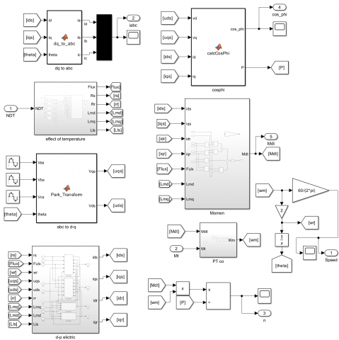
The research results evaluate the variation in the operating characteristics of the LSPMSM under different motor temperatures of 75℃, 90℃, 100℃, 120℃, and 130℃ at rated load. The simulation model of the motor developed in Matlab/Simulink is illustrated in Figure 1.
Figure 1. The LSPMSM model was simulated using Matlab/Simulink
The proposed model is developed under the assumptions that the magnetic circuit operates in the unsaturated region, the rotor structure is symmetrical, and the temperature distribution within the LSPMSM is uniform.
3.1 Speed characteristics
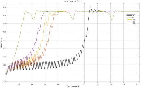
When the motor temperature varies at 75℃, 90℃, 100℃, 120℃, and 130℃, the speed characteristics are obtained as shown in Figure 2.
From Figure 2, it can be observed that the starting process of the LSPMSM varies significantly. At 75℃, the speed increases slowly, with considerable oscillations before reaching the synchronous region. As the temperature rises, the speed curve reaches synchronous speed more quickly and with fewer oscillations, indicating an improved synchronization capability. This behavior can be explained by the increase in rotor resistance with temperature, which enhances the starting torque.
However, at 130℃, although the motor initially reaches a high speed rapidly, it fails to maintain synchronous operation, indicating the negative impact of high temperature on its operating characteristics. This phenomenon can be explained by the fact that at 130℃ the magnet flux is significantly weakened, which may even lead to irreversible demagnetization of the permanent magnets, preventing the LSPMSM from operating in synchronous mode. To provide a quantitative assessment, the characteristic parameters are presented in Table 2.
Figure 2. Starting speed characteristics of the LSPMSM
Table 1. Parameters of the test LSPMSM
|
Symbol |
Description |
Value |
Unit |
|
p |
Number of pole pairs |
2 |
|
|
rs |
Stator resistance |
3.6 |
Ω |
|
rr |
Rotor resistance |
2.11 |
Ω |
|
f |
Supply frequency |
50 |
Hz |
|
Lls |
Stator leakage reactance |
13 |
mH |
|
Llr |
Rotor leakage reactance (referred) |
13.5 |
mH |
|
Lmd |
Direct-axis synchronous reactance |
57.9 |
mH |
|
Lmq |
Quadrature-axis synchronous reactance |
260 |
mH |
|
J |
Moment of inertia |
0.0154 |
kg.m2 |
|
Ldm |
Rated load torque |
14 |
N.m |
Table 2. Parameters for evaluating the speed characteristics
|
T(℃) |
Transient Time-tts (s) |
Maximum Speed (rpm) |
Steady-State Speed (rpm) |
|
75 |
1.679 |
1606 |
1500 |
|
90 |
1.04 |
1502 |
1500 |
|
100 |
0.88 |
1500 |
1500 |
|
120 |
0.82 |
1504 |
1500 |
|
130 |
Asynchronous |
1513 |
Asynchronous |
Based on Table 2, it can be observed that at temperatures from 75℃ to 120℃, the motor successfully synchronizes at the steady-state speed of 1500 rpm, with the transient time decreasing from 1.679 s to 0.82 s as the temperature rises to 120℃. The maximum speed fluctuates around 1500 rpm and tends to approach the synchronous value at higher temperatures, indicating a faster and smoother synchronization process. However, at 130℃, the motor fails to achieve synchronization despite reaching a maximum speed of 1513 rpm. This result demonstrates that when the temperature exceeds the critical threshold, the magnet flux is significantly weakened, leading to the loss of synchronism and negatively affecting the operational reliability of the LSPMSM.
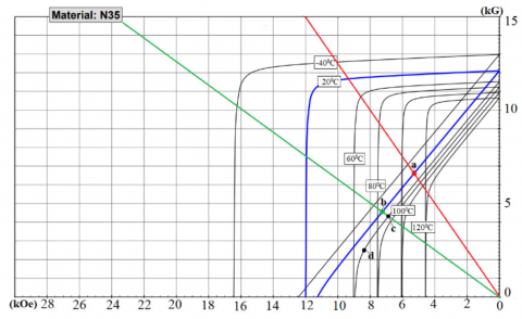
The results of this study are consistent with those reported in the study by Fonseca et al. [20], which indicated that an increase in temperature causes the knee point of the demagnetization curve to shift upward, thereby enhancing the susceptibility of the permanent magnet to thermal demagnetization, as illustrated by the demagnetization characteristics in Figure 3.
Figure 3. Demagnetization characteristic curve of NdFeB [20]
These findings confirm that the proposed model provides a reliable and accurate representation of the temperature effects on the operating characteristics of the LSPMSM, exhibiting excellent agreement among theoretical predictions, simulation outcomes, and experimental results reported in prior research.
3.2 Torque characteristics of the LSPMSM
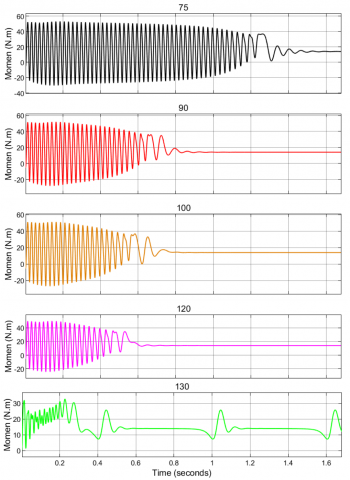
The torque characteristics of the LSPMSM are shown in Figure 4.
Figure 4. Starting torque characteristics of the LSPMSM
From Figure 4, a clear variation in the torque characteristics over time at different temperature levels during the starting process can be observed. At lower temperatures (75–120℃), the initial torque exhibits large-amplitude oscillations, which gradually decrease and stabilize as the motor reaches synchronism. With increasing temperature, the oscillations become shorter in duration, the transient period is reduced, and the torque curve approaches the steady state more rapidly. However, at 130℃, the torque exhibits small and irregular oscillations and fails to maintain a stable state, reflecting the loss of synchronism at this temperature. The detailed parameters are presented in Table 3.
Table 3. Torque characteristic parameters
|
T(℃) |
Transient Time-tts (s) |
Maximum Torque (N.m) |
Torque at Synchronism (N.m) |
|
75 |
1.89 |
53.18 |
14.02 |
|
90 |
1.235 |
52.01 |
14.02 |
|
100 |
1.112 |
51.27 |
14.02 |
|
120 |
1.031 |
50.04 |
14.02 |
|
130 |
Asynchronous |
32.82 |
Asynchronous |
From Table 3, it can be observed that the maximum torque decreases as the temperature increases, from 53.18 N.m at 75℃ to 50.04 N.m at 120℃. Nevertheless, at these temperature levels, the synchronous torque remains stable at 14.02 N.m. The transient time also decreases from 1.89 s (75℃) to 1.031 s (120℃). At 130℃, however, the maximum torque drops to only 32.82 N.m, and the motor fails to achieve synchronism. This reflects a significant reduction in the magnet flux caused by elevated temperature, leading to instability and the inability to meet operational requirements.
3.3 Current characteristics of the LSPMSM
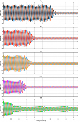
The current characteristics of the LSPMSM during starting at different temperatures are shown in Figure 5.
Figure 5. Operating phase current characteristics of the LSPMSM
As observed in Figure 5, the current characteristics at 75℃, 90℃, 100℃, 120℃, and 130℃ indicate that the starting current initially exhibits strong oscillations with large amplitude, which gradually decrease and converge toward a stable value once the motor reaches synchronism. With increasing temperature, the transient period becomes shorter and the current stabilizes more rapidly. However, at 130℃, the current shows irregular oscillations and fails to converge to a stable value, reflecting the inability of the motor to achieve synchronism at this temperature. The detailed parameters are presented in Table 4.
According to Table 4, the transient time decreases from 1.906 s at 75℃ to 1.046 s at 120℃, indicating an improved synchronization capability as the temperature rises. The peak current decreases from 25.81 A to 24.25 A within the range of 75–120℃, while the operating current slightly increases from 3.75 A to 3.85 A, suggesting that the steady-state current remains stable and is less affected in this temperature range. In contrast, at 130℃, the peak current drops to only 20.21 A, but the operating current becomes unstable and oscillatory, indicating that the motor loses its ability to maintain synchronous operation due to the adverse impact of high temperature on the magnet flux.
Table 4. Operating current parameters
|
T(℃) |
Transient Time-tts (s) |
Operating Current (A) |
Peak Current (A) |
|
75 |
1.906 |
3.75 |
25.81 |
|
90 |
1.306 |
3.78 |
25.03 |
|
100 |
1.127 |
3.81 |
24.98 |
|
120 |
1.046 |
3.85 |
24.25 |
|
130 |
Not determined |
Not determined |
20.21 |
3.4 Power factor cosφ and efficiency characteristics of the LSPMSM
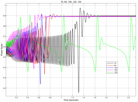
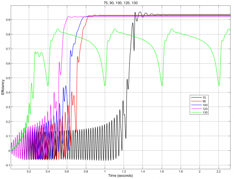
The power factor and efficiency are important characteristics that reflect the operating performance of the LSPMSM. Under increasing temperature conditions, the obtained power factor and efficiency are illustrated in Figure 6 and Figure 7, respectively:
Figure 6. Power factor characteristics
Figure 7. Efficiency characteristics
From Figure 6 and Figure 7, the power factor and efficiency at temperatures of 75℃, 90℃, 100℃, 120℃, and 130℃ indicate that within the range of 75-120℃, both parameters decrease as the temperature increases. At 130℃, however, both characteristics exhibit strong oscillations and fail to converge to stable values. The obtained values are presented in Table 5.
Table 5. Power factor and efficiency values
|
T(℃) |
Power Factor |
Efficiency (%) |
|
75 |
0.898 |
93.5 |
|
90 |
0.895 |
93.02 |
|
100 |
0.893 |
92.67 |
|
120 |
0.889 |
91.96 |
|
130 |
Fluctuating |
Fluctuating |
Based on Table 5, it can be observed that the power factor slightly decreases from 0.898 at 75℃ to 0.889 at 120℃, while the efficiency also declines from 93.5% to 91.96%. This reflects the degradation of both power factor and efficiency as the temperature increases. The observed decrease in power factor and efficiency can be attributed to the temperature-induced weakening of the permanent magnet flux, the rise in conductor losses, and the increased degree of asynchronism in the LSPMSM under elevated thermal conditions. At 130℃, however, both parameters fluctuate and fail to reach stable values, demonstrating that at this temperature threshold, the severe deterioration of the magnetic characteristics significantly affects the operational capability and efficiency of the LSPMSM.
The analysis results indicate that temperature has a significant impact on the operating characteristics of the LSPMSM. At temperatures between 75℃ and 120℃, the motor can still start and successfully synchronize at a steady-state speed of 1500 rpm. The transient time decreases from 1.679 s at 75℃ to 0.82 s at 120℃, demonstrating faster synchronization capability with increasing temperature. The maximum torque decreases from 53.18 N.m (75℃) to 50.04 N.m (120℃), while the synchronous torque remains constant at 14.02 N.m. The peak current slightly decreases from 25.81 A (75℃) to 24.25 A (120℃), whereas the operating current increases from 3.75 A (75℃) to 3.85 A (120℃). The power factor declines from 0.898 (75℃) to 0.889 (120℃), and the efficiency drops from 93.5% to 91.96%, highlighting a deterioration in performance as temperature rises.
At 130℃, the motor fails to achieve synchronism, with speed and torque exhibiting irregular oscillations, unstable current, and large fluctuations in both power factor and efficiency. The maximum torque decreases to only 32.82 N.m, while the peak current drops to 20.21 A, indicating a severe reduction of the magnet flux that results in the loss of the motor’s ability to maintain synchronous operation.
Thus, the research results have demonstrated that for each design specification, the LSPMSM has a certain operating temperature limit to ensure stable performance. These findings provide an important basis for supporting the design process, selecting appropriate magnet materials, and developing cooling solutions, while also serving practical purposes in motor monitoring and maintenance in industrial applications, thereby ensuring reliability and extending equipment lifetime.
[1] Anh, T.L., Nhu, Y.D, Thac, N.K. (2025). Studying the effect of voltage unbalance on the working characteristics of LSPMSM. Journal Européen des Systèmes Automatisés, 58(1): 65. https://doi.org/10.18280/jesa.580108
[2] Baranski, M., Szelag, W., Lyskawinski, W. (2021). Experimental and simulation studies of partial demagnetization process of permanent magnets in electric motors. IEEE Transactions on Energy Conversion, 36(4): 3137-3145. https://doi.org/10.1109/TEC.2021.3082903
[3] Baranski, M., Szelag, W., Lyskawinski, W. (2022). Modelling and experimental verification of temperature effects on back electromotive force waveforms in a line start permanent magnet synchronous motor. COMPEL - The International Journal for Computation and Mathematics in Electrical and Electronic Engineering, 41(5): 1491-1504. https://doi.org/10.1108/COMPEL-07-2021-0228
[4] Le, T.A., Lan, N.T., Do, N.Y. (2025). Investigating the size of permanent magnets to maximize the LSPMSM’s efficiency. IJE TRANSACTIONS C, 39(6): 1369-1381. https://doi.org/10.5829/ije.2026.39.06c.06
[5] Li, D., Wang, S., Chen, X., Tang, C. (2024). Calculating the temperature rise during the starting process of a large-capacity line start permanent magnet synchronous motor. In 2024 IEEE 8th Conference on Energy Internet and Energy System Integration (EI2), Shenyang, China, pp. 2746-2749. https://doi.org/10.1109/EI264398.2024.10991880
[6] Bala, M., Jana, C., Chowdhury, S.K., Sil, A. (2023). Modeling and simulation of LSPMSM for estimation of thermal effect during different load condition. International Journal of Computer Sciences and Engineering, 11(2): 1-8. https://doi.org/10.26438/ijcse/v11i12.18
[7] Baranski, M., Szelag, W., Lyskawinski, W. (2020). Analysis of the partial demagnetization process of magnets in a line start permanent magnet synchronous motor. Energies, 13(21): 5562. https://doi.org/10.3390/en13215562
[8] Palangar, M.F., Mahmoudi, A., Kahourzade, S., Soong, W.L. (2020). Electromagnetic and thermal analysis of a line-start permanent-magnet synchronous motor. In 2020 IEEE Energy Conversion Congress and Exposition (ECCE), Detroit, MI, USA, pp. 502-508. https://doi.org/10.1109/ECCE44975.2020.9235632
[9] Cao, Z., Li, W., Li, J., Zhang, X., Li, D., Zhang, M. (2017). Research on the temperature field of high-voltage high power line start permanent magnet synchronous machines with different rotor cage structure. Energies, 10(11): 1829. https://doi.org/10.3390/en10111829
[10] Yang, Y., Yan, B., Wang, X. (2024). Dynamic model of a line-start permanent magnet synchronous motor equipped with hybrid rotor. IEEE Transactions on Transportation Electrification, 10(2): 2974-2987. https://doi.org/10.1109/TTE.2023.3305650
[11] Yan, B., Wang, X., Yang, Y. (2019). Parameters determination and dynamic modelling of line-start permanent-magnet synchronous motor with a composite solid rotor. IET Electric Power Applications, 13(1): 17-23. https://doi.org/10.1049/iet-epa.2018.5064
[12] Li, D., Zhang, B., Chen, Y., Liu, Z., Teng, X., Wu, J., Yang, L. (2023). Temperature calculation of a large capacity of line start permanent magnet synchronous motor in the starting process. In 2023 IEEE International Conference on Applied Superconductivity and Electromagnetic Devices (ASEMD), Tianjin, China, pp. 1-2. https://doi.org/10.1109/ASEMD59061.2023.10368964
[13] Tasouijan, S., Lee, J., Grigoriadis, K., Franchek, M. (2021). Robust linear parameter-varying output-feedback control of permanent magnet synchronous motors. Systems Science & Control Engineering, 9(1): 612-622. https://doi.org/10.1080/21642583.2021.1974600
[14] Baradieh, K.I., & Al-Hamouz, Z. (2018). Modelling and simulation of line start permanent magnet synchronous motors with broken bars. Journal of Electrical & Electronic Systems, 7(2): 259. https://doi.org/10.4172/2332-0796.1000259
[15] Maraaba, L.S., Al-Hamouz, Z.M., Abido, M.A. (2018). Mathematical modeling, simulation and experimental testing of interior-mount LSPMSM under stator inter-turn fault. IEEE Transactions on Energy Conversion, 34(3): 1213-1222. https://doi.org/10.1109/TEC.2018.2886137
[16] Tuan, L.A., Nhu, D.Y., Khanh, N.T. (2025). Effect of phase angle unbalance on working characteristics of LSPMSM during transient process. IJE TRANSACTIONS B, 39(2): 454-464. https://doi.org/10.5829/ije.2026.39.02b.13
[17] Liang, J., Liang, K., Shao, Z., Niu, Y., Song, X., Sun, P., Feng, J. (2024). Research on temperature-rise characteristics of motor based on simplified lumped-parameter thermal network model. Energies, 17(18): 4717. https://doi.org/10.3390/en17184717
[18] Faramarzi Palangar, M., Mahmoudi, A., Kahourzade, S., Soong, W.L. (2021). Simultaneous efficiency and starting torque optimization of a line-start permanent-magnet synchronous motor using two different optimization approaches. Arabian Journal for Science and Engineering, 46(10): 9953-9964. https://doi.org/10.1007/s13369-021-05659-8
[19] Hussein, I., Al-Hamouz, Z., Abido, M.A., Milhem, A. (2018). On the mathematical modeling of line-start permanent magnet synchronous motors under static eccentricity. Energies, 11(1): 197. https://doi.org/10.3390/en11010197
[20] Le Anh, T., Bien, T.T., Xuan, C.N., Do Anh, T., Do Nhu, Y. (2024). Analysis of permanent magnet demagnetization during the starting process of a line-start permanent magnet synchronous motor. Engineering, Technology & Applied Science Research, 14(6): 17900-17905. https://doi.org/10.48084/etasr.8576
[21] Srinivasan, K., Delgado, F.P., Hofmann, H., Sun, J. (2025). Nonlinear magnetics model for permanent magnet synchronous machines capturing saturation and temperature effects. IEEE Transactions on Energy Conversion. https://doi.org/10.1109/TEC.2025.3599748
[22] Fonseca, D.S.B., Santos, C.M.C., Cardoso, A.J.M. (2017). Modelling of a line-start permanent magnet synchronous motor, using empirical parameters. In Proceedings of the International Conference on Engineering (ICEUBI2017), Covilhã, Portugal, pp. 1518-1528. http://hdl.handle.net/10400.6/7993
[23] Maraaba, L.S., Al-Hamouz, Z.M., Abido, M.A. (2016). Modeling and simulation of line start permanent magnet synchronous motors with asymmetrical stator windings. In Proceedings of the IECON 2016 – 42nd Annual Conference of the IEEE Industrial Electronics Society, Florence, Italy, pp. 1698-1703. https://doi.org/10.1109/IECON.2016.7793412
[24] Baranski, M., Demenko, A., Szelag, W., Lyskawinski, W. (2024). Experimental verification of temperature effects on functional parameters in a line start permanent magnet synchronous motor. IET Science, Measurement & Technology, 18(9): 491-498. https://doi.org/10.1049/smt2.12206
[25] Zawilak, T. (2020). Influence of rotor’s cage resistance on demagnetization process in the line start permanent magnet synchronous motor. Archives of Electrical Engineering, 69(2): 249-258. https://doi.org/10.24425/aee.2020.133023
[26] Selvam, K., Sahoo, S. (2020). Effect of temperature rise in magnetic materials and deviation of torque in permanent magnet synchronous motor. In AIP Conference Proceedings, Bikaner, India, pp. 110015. https://doi.org/10.1063/5.0001534
[27] Zhang, S., Li, S., He, L., Restrepo, J.A., Habetler, T.G. (2021). Rotor thermal monitoring scheme for direct-torque-controlled interior permanent magnet synchronous machines via high-frequency rotating flux or torque injection. arXiv preprint arXiv:2106.02116. https://doi.org/10.48550/arXiv.2106.02116
[28] Tian, W., Wang, L., Bai, X., Han, Z., et al. (2024). Research on transient characteristics of an aviation starter motor under low temperature and pressure. Energies (19961073), 17(24): 6258. https://doi.org/10.3390/en17246258
[29] Le, T.L., Lan, N.T., Do, N.Y., Ho, V.B. (2025). Studying the effect of PM thickness on the back-EMF and power factor of LSPMSM. Journal Européen des Systèmes Automatisés, 58(3): 493. https://doi.org/10.18280/jesa.580307