Mario L. Ferrari*![]() | Lucia Cattani
| Lucia Cattani![]() | Anna Magrini
| Anna Magrini![]()
© 2025 The authors. This article is published by IIETA and is licensed under the CC BY 4.0 license (http://creativecommons.org/licenses/by/4.0/).
OPEN ACCESS
The aim of this paper is the modelling of a smart polygeneration grid and the development of its Energy Management System (EMS) for real-time optimal operations, minimizing variable costs. The proposed grid includes two different demands: water and cooling energy. While water can be obtained from the aqueduct or from an Atmospheric Water Generator system (AWG), cooling energy can be produced from a devoted cooler or from the chilled air of the AWG. The integration with renewable sources in the form of photovoltaic panels is also proposed. Moreover, the grid includes a water tank and a thermal storage system to have additional management flexibility and to avoid money losses in case of extra-productions. While the optimized management is common in electrical energy smart grids, the application of EMS tools in such polygenerative grids including water generation is quite rare. Following the development and validation of component models, attention is focused on the EMS details and its application aspects. To assess the EMS performance, the results obtained with the application of this new tool have been compared with a simple traditional management, showing the obtained economic and environmental benefits.
Energy Management System (EMS), polygeneration grid, atmospheric water generator, storage
Since important issues for the human development regard the access to clean water (UN goal N.6 [1]) and clean energy (UN goal N.7 [1]), innovative efforts to integrate these aspects into a smart polygenerative grid have significant potentiality of market penetration. Considering the current water scarcity situation affecting more than two billion people [2] and the future negative forecast due to the climate change process [3], urgent actions are necessary for recycling, better resource use, or the application of technologies based on alternative sources. Considering different alternative solutions, water extraction from air (or Atmospheric Water Generation (AWG)) started to be a competitive approach based on different techniques: radiative cooling, vapour concentration with sorption-desorption techniques, and active cooling [4]. The third technique (the most diffused and commercial one [5]) is based on a reverse cycle, operating with an electricity-powered compressor, including air flow cooling below the dew point [6]. This solution can provide from tens to thousands litres of water per day, depending on the system size and the ambient conditions. However, an important drawback of this water generation regards the energy consumption [7] that, for this reason, links water production to energy management aspects. This is a very important issue in case water needs to be purified due to filtering systems, increasing such consumption [8]. Energy consumption is one of the main concerns about the sustainability of atmospheric water.
A viable way to address the energy issue consists in employing advanced AWGs expressly studied to be integrated with Heating, Ventilation, Air Conditioning (HVAC) systems [8]. The water harvesting cycle, by direct cooling, gives as secondary effects a flux of dry-cooled air and a potential heating flux coming from the condenser. Advanced integrated AWGs are expressly designed in order to transform these secondary effects into useful effects [9]. In such a way, the overall energy efficiency of the system is notably increased, as the machine gives three contributions, water, cooling and heating, with the same energy input [9]. Therefore, atmospheric water becomes a sustainable alternative water source [9]. Nevertheless, in order to be really effective, such a kind of AWGs requires to be duly integrated in the existing HVAC systems.
Due to the extensive application of alternative renewable sources (such as photovoltaic panels (PVs)), important requirement for the decarbonization target [10], the integration with storage solutions is mandatory for both water and energy generation. For this reason, this work includes a tank for clean water and a tank for cooling water. Although more complex devices could be considered (e.g. phase change materials), in this work simple water tanks are considered because attention is focused on the integration and the management approach rather than on innovative technology development. However, the presented approach is general and easily transferable to different types of energy storage technologies. The application of these tanks is essential to store excessive generation and to minimize variable costs due to a proper device management [11].
Due to these integration aspects, energy management is important to pursue optimization objectives, such as cost minimization [12]. Although the application of an Energy Management System (EMS) is an extensively studied topic in smart grids for heat and electricity generation [13-15], the EMS technology is innovative for the application of AWGs. Especially in polygeneration grids equipped with different energy sources, different generation technologies (including the AWG for water), and/or devoted to generation of different useful flows (such as water, cooling energy, etc.), a robust EMS is essential to operate the grid in optimal conditions. This is important not only for the cost point of view, but also for reducing the environmental impact minimizing emissions (especially in case of integration with fossil fuels or the utilization of an electrical grid not based on zero-emission generation). For this reason, this work focuses special attention on the development of a real-time EMS tool to minimize variable costs during operations against standard management approaches.
The polygeneration grid considered in this work was designed to integrate an advanced AWG system with a renewable source (PV panels) and some traditional components (a chiller and connections to the national water and electricity distribution grids). Storage technology was also included for amplifying the management degrees of freedom (essential aspect for the integration of non-dispachable renewable sources).
2.1 Grid layout
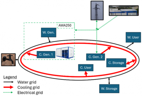
The polygeneration grid includes the distribution of water and cooling energy in the form of chilled air (Figure 1). The water grid is also equipped with a connection with the aqueduct. Thanks to these devoted grids, it is possible to satisfy the related demands (represented with the “W. User” and the “C. User” in Figure 1). Moreover, an electrical grid is also present to supply the electricity to the chillers included in this system: an AWA250 for producing both water and cooling energy and a heat pump used just for the cooling side [16]. Due to the local electricity production with PVs, an integration with renewable-source generation is also present and the connection to the general electrical distribution grid is based on two-way exchanges. Finally, both water and cooling grids are equipped with storage devices (water tanks for both cases – with an air/water heat exchanger for the cooling energy side). This layout could represent a system integration for application in different cases ranging from residential or commercial districts to small industries or industrial sites.
Figure 1. Polygeneration grid layout
2.2 Description of the involved components
The main component considered in this work, for studying the application of an EMS to a grid including the distribution of both water and cooling energy, is the advanced integrated AWG machine AWA250 [16]. It is designed to obtain the useful effects of water extraction from air thanks to the application of a reverse cycle. An external air flow is provided to the machine with fans. Then, following a mechanical filtration, it is cooled below its dew point for obtaining the atmospheric water harvesting. These AWG machines are designed for an optimal integration with buildings, considering that the air flow can be used for the cooling system, as demonstrated in a study involving hotel laundries [17]. Moreover, the heat discharged at the condenser side can be used for heating the domestic water, resulting in additional cost and energy savings. Although in this paper the heating energy is not used, considering no presence of heating demand, in the application shown in the study [17], using both cooling and heating energies, it was obtained a saving of about 80,000 $ per year. Although the water quality aspects are not included in the discussion of this paper because they are linked to the application, their impact on the AWG was carefully analysed in previous works [18, 19]. In the activity discussed in the study [17], machines included materials certified for food contact. Moreover, in study [19] the produced water was tested and demonstrated comparable to high-quality bottled water. The AWG machine (AWA250), considered in this paper, works with R134a as refrigerant fluid and it is composed of these main components: (i) 30 kW compressor, (ii) air treatment unit for 100 kW cooling capacity, (iii) condenser based on a plate heat exchanger, (iv) evaporator and condensation fans.
The “C. Gen. 2” in Figure 1 is a heat pump (used only for the cooling side) supplied by Mayekawa Europe [20]. This device is chosen for this activity because it is available in the Innovative Energy Systems laboratory of the University of Genoa. It includes a superheater and a 6-cylinder reciprocating compressor driven by an electric motor (11 kW maximum active power). The working fluid is normal-butane (R600), and the COP (cooling side) is in the 1.31-2.08 range, as referred on the measurements reported in the study [20]. Although this is a water/water heat pump, the connection with the cooling grid is obtained with a water/air heat exchanger.
Also for the photovoltaic panels this work refers to the installed devices in the Innovative Energy Systems laboratory. They are 6 single-crystal units for a total maximum power of 1.1 kWp. They nominal efficiency is 14.5% [14]. However, the data used in this work are significantly lower than the 1.1 kWp due to significant component aging (they were installed more than 10 years ago).
To conclude this component presentation, it is important to report the details for the storage devices: while the water grid includes a 2000 l tank, the cooling grid is equipped with a chilled water tank for a storage maximum capacity of 2000 kWh.
Since the target of this activity is the EMS development and verification, no specific size optimization was performed on the components. Their size was chosen on the basis of available market components (e.g. for the AWA250), of existing devices available in the laboratory (for the R600 chiller), and to have flexibility for storing water and cooling energy daily operations (starting from the analysis reported in study [12]).
For the EMS development and the related performance assessment through simulations, it was essential to develop real-time models for the involved components. Due to the necessity to have only global values (e.g., produced, consumed or stored power values) and fast calculation performance, simplified models were used on the basis of 0-D approaches (with input-output balance equations) or interpolation of maps (steady-state part) connected to first order delay tools (transient response). This approach was already presented and successfully validated in different previous works, starting from study [12] (a preliminary activity on AWG integration) to study [21] (an application of 0-D models in real-time calculations).
3.1 Development of component models
The model of the AWA250 AWG system was developed with design data from the manufacturer’s web site [16], using literature data [17] and other data for off-design conditions. So, the steady-state part of the model is based on interpolation of performance maps to calculate the values of produced water, cooling power and electrical power consumed at different operating conditions. Due to the influence of these important parameters, they are functions of ambient temperature and relative humidity. A further model part was implemented for the time-dependent response: two subsequent first order delay blocks were used. Due to this very simplified approach, the time constant setting was carried out on the basis of experimental data. The validation of this model was reported in the study [12] considering the cooling side of a scaled-up heat pump available in in the Innovative Energy Systems laboratory at the University of Genoa [22]. During a component start-up and shutdown phase, a good matching (simulation versus experimental data) was obtained in the study [12]: maximum errors close to ±3% in quasi steady-state conditions and accurate calculation of transient response. Considering that measurement accuracy was in the ±3% range for the power values reported in the study [12], the obtained performance was considered good for the purpose of this analysis.
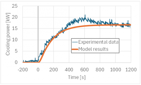
A similar approach was considered for the heat pump whose cooling side provides the additional cooling energy to the grid (“C. gen. 2” in Figure 1). While the steady-state performance modelling was based on the measured data reported in the study [20], the transient response was based on single first order delay blocks. Following preliminary settings of this time constant, the model was successfully validated against experimental data. For instance, Figure 2 shows the good matching between calculations and experimental measurements (accuracy in the ±3% range) for the cooling power produced by the R600 heat pump during a start-up phase.
Figure 2. Heat pump model validation (cooling power)
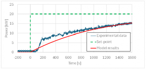
The model of the thermal storage vessel was based on global power input-output balance to calculate its State of Charge. Moreover, a single first order delay block was included for simulating the time-dependent response. It was modelled considering a system composed of different 500 l chilled water tanks installed in parallel. To be general, since the amount of tanks depends on the operative temperature difference, no detailed design is included in this work and every analysis is reported in the form of inlet-outlet power exchange and stored energy. The validation of this model was performed considering a single 500 l tank internally equipped with a 30 kW electrical heater [23]. In the validation test presented in Figure 3, starting from equilibrium conditions, at time zero the heater set-point was switched to 20 kW. The circuit response that mainly depends on the dimension (thickness of the vessel and the pipes, circuit length, thermal insulation, etc.) was reported in Figure 3. Although the simplified model was not able to calculate details, such as the temperature distribution in the vessel, the model results were able to produce the time-dependent trend with an accuracy level in agreement with the measurements (errors in the ±3% range) and with the accuracy needs of this optimization analysis.
Figure 3. Thermal storage (chilled water tank) model validation
A further model regards the water storage tank. Also, in this case a very simple tool was implemented. It was based on an integrator block to calculate the mass changes on the basis of the inlet/outlet balance of the fresh water. The model development activity included also the calculation of its state of charge (SoC), as a number in the 0-1 range.
3.2 Energy Management System layout
The core of this activity was the development of the Energy Management System (EMS) starting from the preliminary tool presented in the study [12]. The EMS of the entire polygeneration grid was developed to minimize the related variable costs. Considering that the target of this work was the development of a real-time EMS to manage the grid during operations, no component size optimization was performed. Although this could be another important optimization (as in the study [22]), attention is focused on specific component management. The optimizer core is the cost function in Eq. (1) and the linked functions in Eqs. (2)-(3).
$\begin{array}{r}J_{\text {cost }}=c_W \cdot m_{W_{\text {grid }}}+\left(c_{O \& M}+c_{e l}\right) \cdot P_{e l_{A W A 250}} \\ +c_{e l} \cdot P_{e l_{H P}}+c_{O \& M} \cdot P_{e l_{H P}} \cdot C O P_{H P}\end{array}$ (1)
$\begin{aligned} & P_{e l_{\text {AWA250 }}} & =f\left(m_{W_{\text {AWA250 }}}, W E T_{\text {AWA250 }}, R H_{a m b}, T_{a m b}\right)\end{aligned}$ (2)
$C O P_{H P}=f\left(T_{a m b}\right)$ (3)
Water Energy Transformation (WET) is an efficiency parameter related to the atmospheric water generation. It represents the ratio between the needed theoretical energy for condensation and the real machine consumption [6]. Although it is based on the COP concept, for the WET parameter the useful effect is the condensation of atmospheric water.
The objective function in Eq. (1) is minimized by a MATLAB optimizer to have in real-time mode the values of three decision variables: water from the general grid (aqueduct), water produced with the AWA250 $\left(P_{e l_{A W A 250}}\right.$ is dependent on $\left.m_{W_{A W A 250}}\right)$ and the electrical power consumed by the heat pump ($P_{e l_{H P}}$) that is used for the cooling side. The optimization process is based on a constrained non-linear minimization of variable costs [24]. The procedure needs to satisfy both water and cooling demands and the constraints reported in Table 1. Although the application of a MATLAB optimizer implies no specific research activity on the algorithm side, an important innovative aspect of this work regards the application of a real-time EMS on an integrated system including water, cooling energy generation and related storage systems.
Table 1. Optimization process constraints
|
Parameter |
Minimum Value |
Maximum Value |
Unit |
|
Water from the grid |
0.00 |
0.03 |
kg/s |
|
Water from the AWA250 |
0.0 |
0.06 |
kg/s |
|
Cooler electrical power |
0.0 |
11.0 |
kW |
|
Water from the storage tank |
-0.02 |
0.02 |
kg/s |
|
Storage tank for cooling energy |
-30.0 |
30.0 |
kWh |
The management of the storage tanks is based on the cost forecast. As presented in the studies [12, 14], a scheduling is necessary to consider a prediction. For instance, in this analysis, discharging the water tank during low water price periods could be erroneous if the storage system is at low level condition or if the water price is affected by a further decrease. So, in this analysis the following approach is proposed: the tank charging is activated (at its maximum) when the electricity cost is lower than its average value and the AWG is in active phase. In case of the opposite electricity cost situation, the tank is discharged. A similar approach is used for the management of the cooling energy tank. However, in this case the charging of this energy storage system is activable only during operations of one (or both) cooling systems. The utilization of both storage systems is constrained in the 10%-90% range.
The PV panels are included in the EMS considering the related electricity production at zero variable cost. This is included in the EMS as described in the study [12] (a recalculation of the electricity cost through a weighted average with grid electrical energy cost).
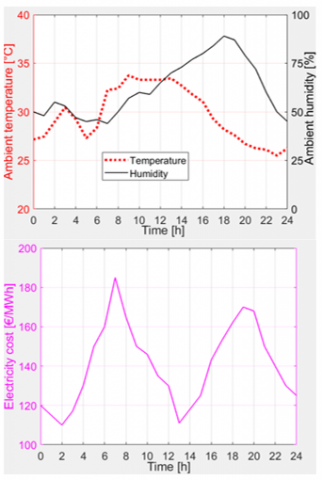
For the case study presented in this paper, the same input values of study [12] are considered. In details, the ambient conditions and the electricity cost during 24 hours are shown in Figure 4. These data are typical of a summer day at intermediate latitude for a location with a double-peak trend for electricity costs [14]. The following further input values are considered (as in the study [12]): 10 €/MWh for Operation and Maintenance (O&M) of both inverse-cycle systems, 2 €/m3 for the water obtained from the aqueduct, and 45 €/MWh for the cooling energy. However, differently from study [12], no cooling energy selling is remunerated because the related demand is considered part of the same entity in charge of the grid management. So, the cooling energy price is used only for valorizing cooling energy in the storage system.
Figure 4. Ambient conditions and electricity cost
The choice of some cost parameters is carried out considering realistic values. For instance, the water cost is representative of Barcelona (Spain) [25] and the O&M cost is derived from study [26]. Finally, an electricity generation from the PV panels is included. The maximum generation is about 650 W at 12:00, as from laboratory measurements.
The simulation results obtained with the EMS are compared with the “No EMS” case (Figure 5). This is a simple approach driven by the necessity to satisfy both demands. So, in the “No EMS” case, thermal loads lower than the heat pump maximum (cooling side) are satisfied by this small system, while higher cooling demands require the AWA250. In case of cooling demands higher than the AWA250 maximum, the heat pump is used in parallel. For the water generation point of view, the aqueduct is used when the AWA250 is off or in case of a water demand higher than the flow generated by this AWG system.
Figure 5. 24-hour simulation: water flow (up) and cooling power (down) values (comparison between the “EMS” and the “No EMS” cases)
The simulation performed with the EMS shows that it is profitable to activate the AWA250 during the central hours of the day due to low electricity cost. During the night, the AWG was not activated (even with low electricity cost) due to the ambient conditions. Lower water producibility was observed compared to daytime conditions with the AWA250, due to the specific weather conditions. It is worth noting, however, that in many climates the opposite occurs, as nighttime typically brings higher relative humidity and lower temperatures than daytime.
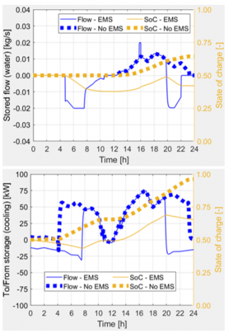
Figure 6 shows the interaction with the storage systems for both generated water and cooling energy. The EMS used the generated water stored in the 2000 l tank for a couple of periods with electricity costs higher than the average (about in the 5-8 and 20-22 hours). As already shown in study [12], the re-charging phase is mainly due to a water generation excess from the AWA250 when it is active for satisfying the thermal demand. A similar trend is obtained for the cooling energy storage tank. However, it is important to highlight that, even if the EMS is constrained in the ±30 kW range for this tank, excess of generated cooling energy (especially in the 14-20 hours) produces significant additional charging effect.
Figure 6. 24-hour simulation: properties related to the storage tanks for generated water (up) and cooling energy (down) (comparison between the “EMS” and the “No EMS” cases)
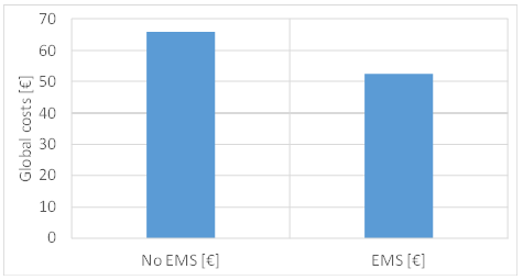
The global variable costs of these 24-hour simulations (Figure 7) show the effectiveness of the EMS against the “No EMS” case. Including also the cost related to re-charging operation of both storage tanks (if the final SoC values is different than the initial ones), the EMS produces a significant decrease in variable costs: -20.6%. In comparison with study [12], the costs show an important increase due to a different organization of the grid: while in study [12] the cooling energy was remunerated, here no earnings are obtained from this side. Although these simulations are based on cost decrease objective, important environmental benefit can be also obtained due to CO2 emission decrease (especially if grid electricity is produced with fossil-fuel sources).
Figure 7. Global variable costs related to this 24-hour simulation (comparison between the “EMS” and the “No EMS” cases)
A further analysis (in Table 2) regards the effect of ±20% changes in different parameters. Since the cost of cooling energy has an impact on the valorization of the stored cooling energy, a cooling cost increase produces a significant decrease in the global costs. Moreover, another property change that can generate an important impact on global variable costs is the cooling demand. Its increase produces cost increase due to the necessity to satisfy it with additional energy consumption on the electrical side. Finally, the electricity produced by the PVs has a negligible impact on the global costs due to the small amount (650 W in the maximum generation) considered in this case. As a final consideration on Table 2, it is important to remark that in all cases the saving in variable costs is significant (-14% in the worst case).
Table 2. Sensitivity analysis on property variations
|
|
EMS [€] |
No EMS [€] |
Saving [%] |
|
Base case |
52.47 |
66.11 |
-20.6 |
|
Cooling cost (-20%) |
55.23 |
74.44 |
-25.8 |
|
Cooling cost (+20%) |
49.71 |
57.79 |
-14.0 |
|
Cooling demand (-20%) |
39.86 |
55.60 |
-28.3 |
|
Cooling demand (+20%) |
62.59 |
75.18 |
-16.7 |
|
PV generation (-20%) |
52.56 |
66.20 |
-20.6 |
|
PV generation (+20%) |
52.38 |
66.03 |
-20.7 |
This paper regards the development of an innovative EMS for a polygeneration grid integrating advanced AWG technology with a heat pump (cooling side), storage systems and electricity generation from PVs. The main innovation is the application of a management technology usually developed for grids including combined heat and power generation to the water supply issues. The work mainly reports the results summarized in the following points.
The results presented in this paper successfully candidate this polygeneration grids to further analyses in the WISHeR PRIN2022 project. They will be based on laboratory tests in cyber-physical mode (as in study [14]) for assessing the EMS performance from the experimental point of view.
This work has been funded by the EU in the Next Generation EU program (Finanziato dall’Unione europea - Next Generation EU, Missione 4 Componente 1, CUP UNIGE D53D23004380006) - PRIN2022 project (n. 2022YSR9LM) titled “WISHeR - Water-collection and Improvement of Sustainability in the HVAC Retrofitting”.
|
AWG |
Atmospheric Water Generator |
|
C. |
Cooling |
|
EMS Gen. |
Energy Management System Generator |
|
HVAC |
Heating, Ventilation, Air Conditioning |
|
PV |
PhotoVoltaic |
|
W. |
Water |
|
Variables |
|
|
c |
cost, € |
|
COP |
Coefficient of Performance, - |
|
J |
cost function, € |
|
m |
mass flow rate, kg/s |
|
P |
Power, W |
|
RH |
Relative Humidity, % |
|
SoC |
State of Charge, 0-1 |
|
T |
Temperature, K |
|
WET |
Water Energy Transformation, - |
|
Subscripts |
|
|
amb |
ambient |
|
AWA250 |
AWG machine considered here |
|
cool |
cooling |
|
el |
electrical |
|
HP |
Heat Pump |
|
O&M |
Operating & Maintenance |
|
W |
Water |
[1] https://sdgs.un.org/goals.
[2] https://www.who.int/news-room/fact-sheets/detail/drinking-water.
[3] Boretti, A., Rosa, L. (2019). Reassessing the projections of the world water development report. NPJ Clean Water, 2(1): 15. https://doi.org/10.1038/s41545-019-0039-9
[4] Tashtoush, B., Alshoubaki, A. (2023). Atmospheric water harvesting: A review of techniques, performance, renewable energy solutions, and feasibility. Energy, 280: 128186. https://doi.org/10.1016/j.energy.2023.128186
[5] Water-from-Air Quick Guide. https://www.atmoswater.com/manufacturers-and-suppliers-of-atmospheric-water-generators--water-from-air-machines.html.
[6] Cattani, L., Magrini, A., Cattani, P. (2021). Water extraction from air: A proposal for a new indicator to compare air water generators efficiency. Energies, 14: 224. https://doi.org/10.3390/en14010224
[7] Wang, J., Yang, Z., Li, Z., Fu, H., Chen, J. (2025). Comprehensive review on atmospheric water harvesting technologies. Journal of Water Process Engineering, 69: 106836. https://doi.org/10.1016/j.jwpe.2024.106836
[8] Cattani, L., Cattani, P., Magrini, A., Figoni, R., Dondi, D., Vadivel, D. (2023). Suitability and energy sustainability of atmospheric water generation technology for green hydrogen production. Energies, 16(18): 6440. https://doi.org/10.3390/en16186440
[9] Cattani, L., Cattani, P., Magrini, A. (2023). Air to water generator integrated system real application: A study case in a worker village in United Arab Emirates. Applied Sciences, 13(5): 3094. https://doi.org/10.3390/app13053094
[10] 2050 Long-Term Strategy. https://climate.ec.europa.eu/eu-action/climate-strategies-targets/2050-long-term-strategy_en.
[11] Ferrucci, T., Fioriti, D., Poli, D., Barberis, S., Roncallo, F., Gambino, V. (2025). Battery energy storage systems for ancillary services in renewable energy communities. Applied Thermal Engineering, 260: 124988. https://doi.org/10.1016/j.applthermaleng.2024.124988
[12] Ferrari, M.L., Catttani, L., Magrini, A. (2024). Energy management system for a smart grid including atmospheric water generation. In Journal of Physics: Conference Series, Genoa, Italy, p. 012027. https://doi.org/10.1088/1742-6596/2893/1/012027
[13] Raggio, M., Ferrari, M.L., Silvestri, P. (2025). Optimised scheduling of a cogenerative subnetwork based on a micro gas turbine and thermal storage with the addition of an innovative solar assisted heat pump and Ni-Zn battery. Applied Thermal Engineering, 259: 124889. https://doi.org/10.1016/j.applthermaleng.2024.124889
[14] Ferrari, M.L., Gini, L., Pascenti, M. (2025). Laboratory tests in cyber-physical mode for an energy management system including renewable sources and industrial symbiosis. Journal of Engineering for Gas Turbines and Power, 147(1): 011020. https://doi.org/10.1115/1.4066249
[15] Norouzi, F., Karimi, H., Jadid, S. (2023). Stochastic electrical, thermal, cooling, water, and hydrogen management of integrated energy systems considering energy storage systems and demand response programs. Journal of Energy Storage, 72: 108310. https://doi.org/10.1016/j.est.2023.108310
[16] Awa Modular 250. https://seas-sa.com/project/awa-modula-250/.
[17] Cattani, L., Magrini, A., Cattani, P. (2018). Water extraction from air by refrigeration—Experimental results from an integrated system application. Applied Sciences, 8(11): 2262. https://doi.org/10.3390/app8112262
[18] Kaplan, A., Ronen-Eliraz, G., Ratner, S., Aviv, Y., Wolanov, Y., Avisar, D. (2023). Impact of industrial air pollution on the quality of atmospheric water production. Environmental Pollution, 325: 121447. https://doi.org/10.1016/j.envpol.2023.121447
[19] Mandal, C.S., Agarwal, M., Reddy, V., Kudapa, V.K. (2021). Water from air–A sustainable source of water. Materials Today: Proceedings, 46: 3352-3357. https://doi.org/10.1016/j.matpr.2020.11.477
[20] Anfosso, C., Gini, L., Mantelli, L., Ferrando, M., Reboli, T., Traverso, A. (2022). Butane-based heat pump for advanced GTCC applications: static and dynamic model validation. In Journal of Physics: Conference Series, Bari, Italy, p. 012092. https://doi.org/10.1088/1742-6596/2385/1/012092
[21] Ferrari, M.L., Mantelli, L., Pascenti, M. (2025). Emulation tests of dynamics and control for a turbocharged SOFC system. Applied Thermal Engineering, 258: 124514. https://doi.org/10.1016/j.applthermaleng.2024.124514
[22] Barberis, S., Rivarolo, M., Bellotti, D., Magistri, L. (2022). Heat pump integration in a real poly-generative energy district: A techno-economic analysis. Energy Conversion and Management: X, 15: 100238. https://doi.org/10.1016/j.ecmx.2022.100238
[23] Reboli, T., Ferrando, M., Mantelli, L., Gini, L., Sorce, A., Garcia, J., Guedez, R. (2022). Gas turbine combined cycle range enhancer-Part 1: Cyber-physical setup. In Turbo Expo: Power for Land, Sea, and Air, Rotterdam, Netherlands, p. V004T06A022. https://doi.org/10.1115/GT2022-82494
[24] Audet, C., Dennis Jr, J.E. (2002). Analysis of generalized pattern searches. SIAM Journal on Optimization, 13(3): 889-903. https://doi.org/10.1137/S1052623400378742
[25] L’Indice dei Prezzi dell’Acqua. https://www.holidu.it/magazine/indice-prezzi-acqua.
[26] Ancona, M.A., Bianchi, M., Biserni, C., Melino, F., Salvigni, S., Valdiserri, P. (2019). Optimum sizing of cogeneration plants by means of a genetic algorithm optimization: A case study. Case Studies in Thermal Engineering, 15: 100525. https://doi.org/10.1016/j.csite.2019.100525