Anwar Hasni*![]() | Hassan El Fadil
| Hassan El Fadil![]() | Abdellah Lassioui
| Abdellah Lassioui![]() | Yassine El Asri
| Yassine El Asri![]() | Marouane El Ancary
| Marouane El Ancary![]() | Hafsa Abbade
| Hafsa Abbade![]() | Mohamed Mouyane
| Mohamed Mouyane![]()
© 2025 The authors. This article is published by IIETA and is licensed under the CC BY 4.0 license (http://creativecommons.org/licenses/by/4.0/).
OPEN ACCESS
This paper presents an advanced control strategy to improve the performance of scalar (V/f) induction motor control by incorporating a robust controller based on the super-twist sliding mode control (STSMC) approach. The proposed method aims to improve stability, speed tracking accuracy, and robustness to disturbances and load variations, while retaining the simplicity of traditional scalar control. The model of an induction motor is simulated via MATLAB/Simulink, and the STSMC controller is optimized using a criterion operating as a function of the ITAE to minimize dynamic error. In order to validate the performance of the solution, real-time implementation is carried out on an experimental test bench on a 0.37 kW induction motor via a dSPACE 1104 board. Experimental results verify the contributions of STSMC to conventional scalar control, such as speed response, speed ripple reduction, and effective disturbance rejection. This hybrid approach is therefore an effective and easy-to-implement solution for the robust control of induction motors.
cruise control, scalar control V/f, induction motors, STSMC controller, dSPACE 1104 board
Induction motor control is essential for most industrial drives due to its performance, ease of installation, and relatively low cost. Among control strategies, the scalar (V/f) method is the most widely used due to its low complexity and ease of implementation, particularly in areas where precise values are not essential. However, this method has some major drawbacks, such as poor dynamic performance, sensitivity to disturbances, and an inability to provide good control accuracy under different operating conditions [1-3].
In view of these constraints, various means have been explored to improve the performance of scalar controls. The most widespread is undoubtedly the use of PID correctors, appreciated for their simplicity of form and their performance in linear regimes. The problem is that they require very precise tuning, which may be inappropriate in a non-linear or disturbed setting [4]. To overcome this limitation, smarter PID optimization methods such as GA, PSO, or even swarm optimization exist to make them more dynamically responsive [5, 6]. In parallel, approaches based on artificial intelligence have also been considered.
Fuzzy logic controllers have made control more flexible by managing signal uncertainty and imprecision, but their operation is highly dependent on rule design [7]. Artificial neural networks (ANNs) have been used for motor dynamics estimation and online control tuning with satisfactory performance, particularly in the presence of nonlinearities [8]. Hybrid approaches have been used in other studies, for example with Fuzzy-PID or ANN-PID, with the aim of exploiting the strengths of both methods [9, 10].
Although these methods have enabled significant advances, they generally present limitations, either in terms of design complexity (for ANNs), or in terms of guaranteed theoretical stability (for fuzzy or purely heuristic techniques). It is in this context that sliding mode control (SMC), and more specifically its super-torsional sliding mode controller, presents itself as an effectively robust and theoretically sound solution. The use of STSMC minimizes the chattering effect, guarantees final convergence to the sliding surface and ensures robustness to uncertainties and disturbances.
Recently, several studies have focused on the investigation and optimization of STSMC controllers. For example, Usha et al. [11] propose a variable gain VGFOST-SMC strategy involving a disturbance observer, applicable to permanent magnet synchronous motors with real-time validation. In addition, the development of third-order STSMC (TO-STSMC) enhances the approach phase and ensures better disturbance rejection [12]. In comparison, the reference work [13] laid the foundations for the field, while these more recent contributions broaden the fields of application to new motor topologies, new control structures, and advanced experimental validations, highlighting the added value and originality of our research.
Nevertheless, the performance of the STSMC controller depends to a large extent on the fine-tuning of its parameters, and it is therefore reasonable to use intelligent optimization algorithms to find the best offline values [14]. For this reason, this paper proposes a new hybrid control strategy, which combines traditional scalar V/f control with an STSMC optimized by an optimization algorithm, with the aim of significantly improving the dynamic behavior and robustness of the system. The proposed control mode was implemented in the MATLAB/Simulink environment, followed by experimental validation. Simulation and experimental results show a qualitative improvement in response time, transient stability, and resistance to mechanical disturbances [15].
The rest of the article is structured to guide the reader progressively from system modeling to overall performance evaluation. Section 2 is devoted to modeling the induction motor, with an explanation of the scalar (V/f) control principle. Section 3 highlights the design of the super-twisting sliding-mode controller, its integration into the speed control loop, and the optimization method chosen for the automatic adjustment of its parameters, aimed at optimizing system efficiency. Section 4 describes the experimental test rig in full, highlighting the technical specifications and hardware choices adopted. Section 5 describes and presents the results obtained by means of simulations and experimental tests in various scenarios, clearly demonstrating the performance enhancement introduced by the proposed method. Section 6 concludes the study by summarizing the main contributions and proposing practical lines of improvement and extension for future research.
2.1 Induction motor model
In this section, a mathematical electromagnetic model of the asynchronous squirrel-cage motor is developed in order to accurately reproduce its dynamic behavior. This model provides an essential basis for comparing the performance results obtained from control simulations with the experimental results measured on the test bench [16]. Given the complex geometry and electromagnetic phenomena characteristic of such a machine, it is necessary to make a number of simplifying assumptions that allow for a usable model while maintaining a good approximation:
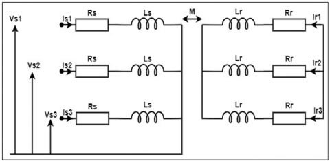
The electrical and magnetic equations of an induction motor can be represented by a system of equations characterizing the electromagnetic interaction of the system, as shown in Figure 1 [17].
Figure 1. Electrical diagram of induction motor
The stator and rotor voltages of the induction motor are given by applying Ohm-Faraday's law to this mesh:
In stator:
$\vec{V}_s=R_s \cdot \vec{I}_s+\frac{d \vec{\Phi}_s}{d t}$ (1)
In rotor (cage, not powered):
$\overrightarrow{0}=R_r \cdot \vec{I}_r+\frac{d \vec{\Phi}_r}{d t}$ (2)
Magnetic fluxes are defined by inductance matrices, assuming material linearity and parameter constancy:
Stator flux:
$\vec{\Phi}_s=L_{s s} \cdot \vec{I}_s+M_{s r}(\theta) \cdot \vec{I}_r$ (3)
Rotor flux:
$\vec{\Phi}_r=L_{r r} \cdot \vec{I}_r+M_{r s}(\theta) \cdot \vec{I}_s$ (4)
Assuming a symmetrical three-phase machine:
Matrix of stator inductances:
$L_{s s}=\left[\begin{array}{ccc}L_s & M_s & M_s \\ M_s & L_s & M_s \\ M_s & M_s & L_s\end{array}\right]$ (5)
Matrix of rotor inductances:
$L_{r r}=\left[\begin{array}{ccc}L_r & M_r & M_r \\ M_r & L_r & M_r \\ M_r & M_r & L_r\end{array}\right]$ (6)
Matrix of mutual inductances:
The sinusoidal dependence of Msr (θ) comes from the distribution of the fem. in the air gap:
$M_{s r}(\theta)=M \cdot\left[\begin{array}{ccc}\cos (\theta) & \cos (\theta+2 \pi / 3) & \cos (\theta-2 \pi / 3) \\ \cos (\theta-2 \pi / 3) & \cos (\theta) & \cos (\theta+2 \pi / 3) \\ \cos (\theta+2 \pi / 3) & \cos (\theta-2 \pi / 3) & \cos (\theta)\end{array}\right]$
$M_{r s}(\theta)=M_{s r}^{\top}(\theta)$ (7)
By injecting the flows (3) and (4) into the voltage Eqs. (1) and (2), we obtain:
Stator equation:
$\vec{V}_s=R_s \cdot \vec{I}_s+\frac{d}{d t}\left(L_{s s} \cdot \vec{I}_s\right)+\frac{d}{d t}\left(M_{s r}(\theta) \cdot \vec{I}_r\right)$ (8)
Rotor equation:
$\overrightarrow{0}=R_r \cdot \vec{I}_r+\frac{d}{d t}\left(L_{r r} \cdot \vec{I}_r\right)+\frac{d}{d t}\left(M_{r s}(\theta) \cdot \vec{I}_s\right)$ (9)
Rotor dynamics follows Newton's law of angular momentum:
$J \cdot \frac{d \Omega}{d t}=C_{e m}-C_r-K_f \cdot \Omega$ (10)
$J$: rotor moment of inertia
$\Omega$: angular velocity
Cem: electromagnetic torque
Cr: resistive torque (load)
Kf: coefficient of viscous friction
2.2 Scalar V/f control
Scalar V/f control, also known as constant flux control, is an open, non-vector control strategy applied to asynchronous motors. It is based on maintaining a constant ratio between the supply voltage V and the mains frequency f in order to keep the stator magnetic flux at a nominal value [18]. According to the fundamental induction motor equations, the stator flux is approximately given by:
$\Phi_s \approx \frac{V_s}{2 \pi f N_s}$ (11)
where:
$\Phi_{\mathrm{S}}$: the stator magnetic flux
Vs: The stator voltage
f: The supply voltage frequency
Ns: The number of turns
Thus, to avoid saturation of the magnetic circuit at low frequency or torque drop at high frequency, we adjust the voltage proportionally to the frequency according to the law:
$V_s(f)=V_n \cdot \frac{f}{f_n}$ (12)
where, Vn and fn are the nominal values. Below a certain threshold frequency, a boost voltage is often added to compensate for the voltage drop across the stator resistance Rs.
V/f control is extremely simple to implement, with no need for complex mathematical transformations. It's economical, too, thanks to the absence of current or speed sensors. This method is ideal for applications with constant torque or low dynamic demand, such as fans or conveyors. It is a reliable solution for simple, low-cost systems [19].
In contrast, V/f control has poor dynamic performance, is very slow, and is sensitive to rapid load changes. It does not respond well to external disturbances or changes in motor parameters. In addition, it causes speed errors in steady state, especially at low frequencies. Finally, its energy efficiency is reduced, mainly when operating at low speeds.
While scalar V/f control is easy to implement, its power is not sufficient under disturbed conditions or with high dynamic requirements. Hence the interest in reinforcing its robustness with advanced controllers, such as STSMC, while maintaining the structural simplicity of V/f [20].
3.1 Overview of the sliding mode control
Sliding mode control (SMC) is a nonlinear control method designed to force the system’s trajectory onto a predefined sliding surface $s(x, t)=0$ and maintain it there despite disturbances and uncertainties [21]. It typically works in two phases:
Reaching phase: The controller drives the state towards the sliding surface.
Sliding phase: Once on the surface, the system slides along it, with dynamics defined by the surface itself.
The system model is given by:
$\dot{x}=f(x, t)+g(x, t) u+d(t)$ (13)
where:
$x \in \mathbb{R}$ is the state (e.g., speed error), $u \in \mathbb{R}$ is the control input, $f(x, t)$ is the known nonlinear system dynamics, $g(x, t) \neq 0$ is the known input gain, $d(t)$ is a bounded disturbance.
The sliding surface is typically defined as:
$s(t)=\frac{d}{d t} e(t)+\lambda e(t)$ (14)
where, $e(t)=\omega^*(t)-\omega(t)$ is the tracking error and $\lambda>0$ is a design parameter.
Sliding mode control offers certain advantages that explain its use in highly uncertain systems. SMC is very robust in the face of modeling uncertainties and external disturbances, forcing the system to maintain a specific trajectory despite internal dynamic fluctuations. Secondly, the discontinuity of the control signal allows for an instantaneous response, which significantly improves dynamic performance, particularly in systems that require precise and rapid regulation. Finally, SMC allows the system to be stabilized even in the event of significant parameter variations, making it an effective control scheme for nonlinear or poorly modeled systems [22].
Despite its advantages, SMC has some serious drawbacks. One of these is chattering, i.e., high-frequency oscillations caused by discontinuous switching of the control signal, which tend to cause premature wear of mechanical actuators. Furthermore, in order to deliver good performance, SMC requires precise knowledge of the system's limits so that control gains can be fully tuned, a requirement that can be difficult to meet in uncertain or complex systems. Finally, this strategy is sensitive to noise measurements, as periodic switching can amplify interference from sensors and thus deteriorate control quality [23].
3.2 Super-twisting sliding mode controller
STSMC is a second-order Sliding Mode Control method that overcomes the chattering problem by employing a continuous control law. It does not require the time derivative of the sliding variable $s(t)$, making it advantageous for realworld systems where derivative information is noisy or unavailable [24].
The control law is defined as:
$\left\{\begin{array}{l}u(t)=-k_1|s(t)|^{1 / 2} \cdot \operatorname{sign}(s(t))+v(t) \\ \dot{v}(t)=-k_2 \cdot \operatorname{sign}(s(t))\end{array}\right.$ (15)
where, $k_1, k_2>0$ are the STSMC gains, $v(t)$ is an adaptive internal variable, $\operatorname{sign}(s(t))$ ensures control action direction.
Super-twisting control, as an extension of second-order sliding mode control, has several crucial advantages. Firstly, it eliminates chattering while retaining the robustness of conventional SMC, making it more compatible with practical implementation. By having a continuous control input, it is more compatible with real actuators, limiting mechanical wear and facilitating hardware integration. Simultaneously, the command law guarantees the finite-time convergence of the sliding variable s(t)→0, resulting in greatly improved dynamic performance and speed of the response. Last but not least, the STSMC is not dependent on the derivative of the sliding surface and is therefore less sensitive to the measurement noise, preventing its growth during the calculation of the command [25]. Despite its many advantages, STSMC does have some limitations to consider. Firstly, setting the gains k1 and k2 is more complex than with conventional SMC, as it must be done rigorously to guarantee both system performance and stability. Secondly, the efficient application of this method requires a differentiable sliding surface, as well as a perturbation whose derivative is bounded, which may not be verified in all physical systems. Finally, due to the introduction of the additional dynamics associated with the integral term v(t), STSMC generates a slightly higher computational cost than first-order SMC control, which can be a constraint in resource-constrained embedded systems.
3.3 Optimizing STSMC controller parameters
In order to improve the dynamic performance of the BLDC motor speed control system, the STSMC controller parameters, in this case the feedback coefficients k1 and k2, are optimized using a genetic algorithm. The main objective of this optimization is to minimize speed tracking errors by reducing certain performance criteria that are well established in the literature [26, 27], such as:
Integral of Absolute Error (IAE):
$I A E=\int_0^T\left|e_1(t)\right| d t$ (16)
Integral of Squared Error (ISE):
$I S E=\int_0^T e_1^2(t) d t$ (17)
Integral of Time-weighted Absolute Error (ITAE):
$I T A E=\int_0^T t \cdot\left|e_1(t)\right| d t$ (18)
In this study, the ITAE index is preferred as the objective function, as it strongly penalizes prolonged errors, thus favoring rapid response with reduced overshoot. The cost function to be minimized is therefore defined by:
$J=\int_0^T t \cdot\left|\Omega_{\text {ref }}(t)-\Omega(t)\right| d t$ (19)
The genetic algorithm is applied to find the optimal values of k1 and k2 that minimize this function. The optimization process follows the following steps:
Generation of an initial random population of candidate solutions, where each individual encodes a pair of payoffs $\left(k_1, k_2\right)$. The genetic algorithm was configured with the following parameters: population size $=50$ individuals, maximum number of generations $=100$, crossover probability $=0.8$, and mutation probability $=0.05$. Each individual was evaluated based on the cost function $J$, and the best solutions were selected according to their performance. Genetic operators such as crossover and mutation were then applied to generate new candidate solutions. This evolutionary process was repeated iteratively until convergence toward the optimal coefficient values, which were found to be $k_1=85.24689$ and $k_2=105.56482$.
This section is devoted to an exhaustive description of the equipment used for experimental validation. It is divided into two major parts. The first concerns the strict identification of the parameters of the chosen induction motor, a fundamental step in guaranteeing the accuracy of the model. The second describes the various equipment used, highlighting their technical characteristics and the reasons for their choice. This methodological structuring ensures a clear traceability of the experimental approach, and provides a better understanding of the actual implementation conditions of the system studied.
4.1 Identification of induction motor parameters
To ensure reliable validation of the proposed approach, this study begins by identifying the parameters of the asynchronous motor used in the system. The motor under test is a three-phase squirrel-cage induction motor. The motor nameplate ratings are given in Table 1. In the present experiment, a star (Y) connection was used.
Table 1. Induction motor nameplate
|
Designation |
Value |
|
Nominal output power |
0.37 KW |
|
Rated frequency |
50 Hz |
|
Rated stator voltage |
220/380 V |
|
Rated stator current |
1.12 A |
|
Rated speed |
1370 rpm |
|
Rated power factor |
0.86 |
|
Number of pole pairs |
2 |
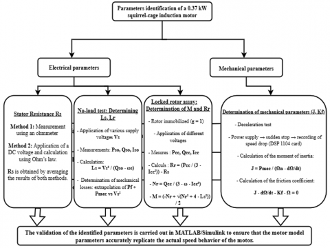
In order to precisely define the parameters of the asynchronous motor, several experimental tests were carried out. These are essential for rigorously defining the electrical and mechanical parameters of the motor, and constitute an important step in the experimental validation of this research. The tests carried out include a no-load test, a short-circuit test, and measurements of the stator resistance. These experiments enable us to determine fundamental quantities such as winding resistance, inductance and internal mechanical losses. Precise knowledge of these parameters is crucial to the development of a reliable dynamic model, which forms the basis of the control strategies developed later. This methodical process guarantees consistency between simulated results and observed experimental performance (see Figure 2).
The values of the electrical and mechanical parameters of the identified induction motor used in this study are presented in Table 2.
Figure 2. The various tests carried out to identify induction motor parameters
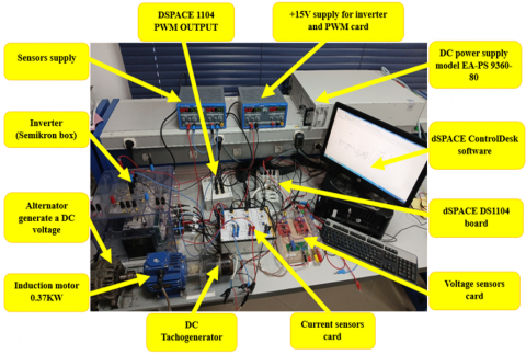
Figure 3. The experimental bench with the various materials used
4.2 Equipment and experimental setup
Experimental validation was carried out on a complete test bench incorporating electromechanical equipment, energy conversion modules, measurement systems, and a real-time control platform. The main actuator is a three-phase asynchronous motor with a rated power of 0.37 kW, mechanically coupled to an alternator producing direct current voltage, as well as a DC Tachogenerator ensuring accurate measurement of rotational speed. The motor is powered by a Semikron inverter, controlled by PWM signals generated by the dSPACE DS1104 real-time card. The latter, integrated into a dedicated computer, simultaneously generates commands and acquires data, using dSPACE ControlDesk software for supervision, parameter adjustment, and real-time measurement recording. Electrical quantities are measured using specialized measurement cards: a current sensor card, used to record the intensity of the currents supplying the motor, and a voltage sensor card, which exploits the proportional relationship between the speed of rotation and the voltage generated by the DC generator, acting here as a tachometric speed sensor. These cards are powered by a dedicated source to ensure the accuracy of the measured signals. The entire system is powered by several separate sources: a high-power EA-PS 9360-80 programmable DC power supply to provide power to the inverter, and a +15 V stabilized power supply for the control circuits and PWM cards. The DC Tachogenerator converts the rotational speed into a proportional voltage that can be directly used by the dSPACE card, thus enabling the control loop to be closed. Thanks to its modular, instrumented, and highly flexible configuration, this test bench faithfully reproduces real operating conditions, providing an optimal environment for the implementation and rigorous validation of the control strategies developed (see Figure 3).
Table 2. Motor parameter values after identification
|
Parameters Identified |
Values |
|
Rs |
25.5 Ω |
|
Rr |
17 Ω |
|
Ls |
0.7948 H |
|
Lr |
0.7948 H |
|
M |
0.6786 H |
|
J |
0.00331 Kg.m2 |
|
Kf |
0.00285 m2/s |
The purpose of this section is to present and analyze, on the one hand, the results obtained from simulations performed in Matlab/Simulink and, on the other hand, the results obtained from experimental validation for the control of an asynchronous motor using a scalar control approach with a Super Twisting Sliding Mode Control controller. The simulation results are analyzed according to two distinct scenarios in order to thoroughly evaluate the performance and robustness of the proposed controller. The first scenario is devoted to evaluating the system's ability to accurately follow the imposed speed reference, while the second examines the robustness of the control by varying the load torque in order to observe the dynamic response of the system. With regard to experimental validation, the study focuses mainly on analyzing the performance of the motor's reference speed tracking.
5.1 Simulation results
5.1.1 First scenario: Tracking performances
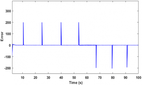
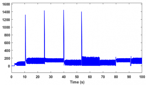
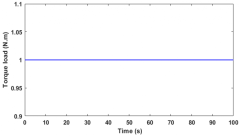
In this first simulation scenario using Matlab/Simulink, the analysis focuses on the motor speed response relative to a predefined setpoint, with a constant load torque set at 1 N.m. The reference speed varies successively according to the sequence [200, 400, 800, 1000, 800, 400] rpm (Figure 4). The results show that in the first step, the motor speed reaches 200 rpm in just 4 seconds, while in subsequent variations, the response time is reduced to 1 second in the case of an increase and 0.8 seconds in the case of a decrease. The tracking error is completely eliminated, as confirmed by Figure 5, which demonstrates the accuracy of the setpoint tracking. Furthermore, the controller output shown in Figure 6 highlights the rapid and effective action of the STSMC controller, which is capable of maintaining the requested speed despite sudden reference variations. All of the results, obtained with a constant load torque (Figure 7), demonstrate the robustness and responsiveness of the control implemented under these steady-state conditions.
Figure 4. Variation in motor speed during a reference speed change under load conditions
Figure 5. Speed error when varying the reference speed with a constant load torque
Figure 6. Controller output during speed reference variations with constant load torque
Figure 7. Load torque applied to the motor
5.1.2 Second scenario: robustness performances
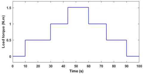
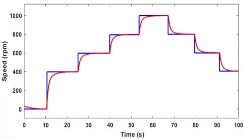
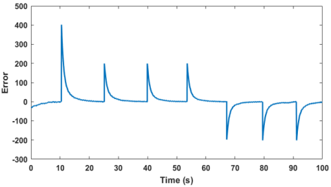
In the second simulation scenario, which focused on evaluating the controller's robustness in the face of external disturbances such as load torque variations, two tests were carried out to analyze its performance in depth. Figure 8 illustrates the motor speed response to these disturbances, where the peak variation exceeds only 0.75% of the reference speed, with a stabilization time of 0.2 s. Figure 9 confirms that the tracking error is completely eliminated after each variation, also in 0.2 s, demonstrating the speed of the system's correction. Figure 10 shows the controller output, which adjusts dynamically to compensate for disturbances and maintain the desired speed. The tests were performed under a variable load torque following the sequence [0, 0.5, 1, 1.5, 1, 0.5, 0] N.m, as shown in Figure 11, highlighting the controller's ability to maintain optimal performance despite changing load conditions.
Figure 8. Speed response during load torque variation
Figure 9. Speed error when varying load torque
Figure 10. Controller output under constant speed reference with varying load torque
Figure 11. The variation of the load torque applied to the motor
5.2 Experimental results
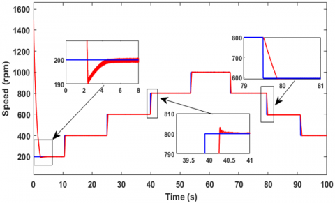
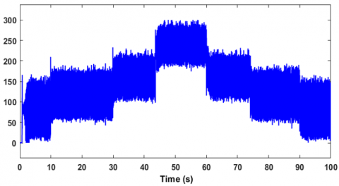
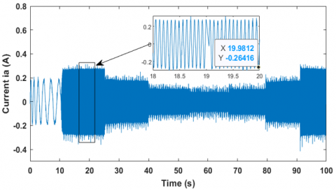
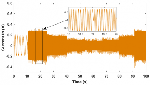
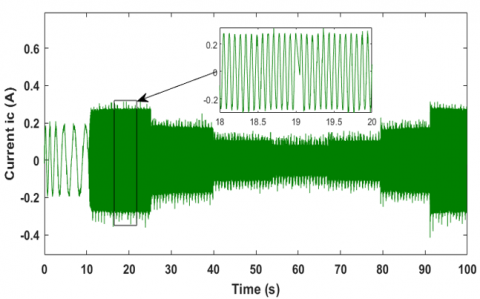
With regard to experimental validation, this step aims to confirm the effectiveness of the improvement made to the scalar control of the induction motor by integrating the optimized STSMC controller. After validation in simulation, the actual implementation was carried out on a test bench in the laboratory, under no-load conditions, in accordance with the equipment available. Figure 12 illustrates the motor's response to a sequence of reference speeds [0, 200, 400, 600, 800, 1000, 800, 600, 400] rpm, with a stabilization time of between 4 and 6 seconds depending on the variations. Figure 13 highlights the complete cancellation of the tracking error approximately 5 seconds after each setpoint change, confirming the system's ability to quickly correct deviations. Figures 14-16 show the supply current consumed by the motor, with an average value of 0.3 A, well below the nominal current of 1.2 A indicated on the nameplate, demonstrating both the energy efficiency and operational reliability of the developed control system.
Figure 12. Experimental validation of motor speed response with reference speed variation
Figure 13. Experimental validation of speed error during speed reference variation
Figure 14. The supply current consumed by the motor phase A
Figure 15. The supply current consumed by the motor phase B
Figure 16. The supply current consumed by the motor phase C
The quantitative results illustrated in Table 3 provide a clear indication of the performance of the optimized super twisting sliding mode command strategy in comparison with traditional PID and SMC controllers. More specifically, the proposed STSMC achieves an overshoot of less than 2%, which represents a reduction of approximately five times compared to PID controllers and two to three times compared to SMC controllers. Similarly, the stabilization time is significantly shorter, from 0.5 s to 0.9 s, compared to PID and SMC with values ranging from 1.6 to 2.2 s and 1.0 to 1.4 s, respectively. In addition, the steady-state error in STSMC is always negligible (≤ 0.2%), indicating that speed tracking is very accurate, even at sudden load changes. These improvements are consistent with the results duly presented in the literature [28, 29], which state that STSMC not only improves dynamic performance but also robustness to system uncertainties and external disturbances. Therefore, this optimized control approach is well suited for industrial applications where accuracy, stability, and fast response are important.
Table 3. Quantitative performance comparison between PID, SMC, and optimized STSMC
|
Controller |
Overshoot (%) |
Settling Time (s) |
Steady-State Error (%) |
|
PID [28] |
10–15 |
1.6–2.2 |
0.8–1.5 |
|
Classical SMC [29] |
4–8 |
1.0–1.4 |
0.3–0.8 |
|
Optimized STSMC |
≤ 2 |
0.5–0.9 |
≤ 0.2 |
In this work, the design, implementation, and experimental validation of a scalar control strategy on a 0.37 kW asynchronous motor, optimized by a super-twisting sliding mode control algorithm, were highlighted. The optimization of STSMC parameters played an important role in the robustness of the system, which is highly tolerant to disturbances and uncertainties commonly encountered in industrial environments. The proposed approach was first confirmed by simulation in MATLAB/Simulink, then tested experimentally on a dedicated test bench. The comparison between the simulation results and those of the experiment was very satisfactory, confirming the accuracy and reliability of the control model developed. The optimized STSMC offers the following main advantages: high dynamic response, accurate tracking of the reference command speed, and high robustness against sudden load variations, while effectively minimizing oscillations and torque ripple. Compared to conventional scalar control strategies, the optimized STSMC is more robust and flexible, without requiring complex flow measurement or estimation. The results confirm that the new control strategy is very well suited for practical industrial implementation, particularly in systems where performance stability under uncertain operating conditions is of the utmost importance. Looking ahead to further improvements, one potential research direction involves the integration of adaptive artificial intelligence techniques to further enhance the autonomy and flexibility of the system. More specifically, approaches such as reinforcement learning for real-time gain programming or fuzzy logic systems for rule-based adaptation can be applied for dynamic adjustment of STSMC parameters in response to changes in load, temperature, or motor aging. This combination would enable the development of intelligent, self-optimizing drive systems capable of ensuring optimal performance throughout the engine's life cycle.
This work was carried out with the support of the Centre National de la Recherche Scientifique et Technique (CNRST), as part of the "PhD-Associate Scholarship - PASS" program.
[1] Otkun, Ö., Demir, F., Otkun, S. (2022). Scalar speed control of induction motor with curve-fitting method. Automatika: Journal for Control, Measurement, Electronics, Computing and Communications, 63(4): 618-626. https://doi.org/10.1080/00051144.2022.2060657
[2] Keskin, B., Eminoğlu, İ. (2022). Optimally tuned PI controller design for V/f control of induction motor. In 2022 International Congress on Human-Computer Interaction, Optimization and Robotic Applications (HORA), Ankara, Turkey, pp. 1-5. https://doi.org/10.1109/HORA55278.2022.9800005
[3] Maghfiroh, H., Saputro, J.S., Adriyanto, F., Sujono, A. Lambang, R.L. (2021). Performance evaluation of fuzzy-PID in speed control of three phase induction motor. In the 6th International Conference on Industrial, Mechanical, Electrical and Chemical Engineering - ICIMECE 2020, 20th October 2020, Solo, Indonesia, p. 012071. https://doi.org/10.1088/1757-899X/1096/1/012071
[4] Mohamed, B., Kamel, K. (2022). Optimal fuzzy logic controller using teaching learning based optimization for asynchronous motor. In 2022 19th International Multi-Conference on Systems, Signals & Devices (SSD), Sétif, Algeria, pp. 1478-1483. https://doi.org/10.1109/SSD54932.2022.9955752
[5] Urooj, A., Nasir, A. (2024). Neural network-based self-tuning control for hybrid electric vehicle engines. Engineering Applications of Artificial Intelligence, 138: 109275. https://doi.org/10.1016/j.engappai.2024.109275
[6] Hasni, A., El Fadil, H., Lassioui, A., El Ancary, M., El Asri, Y., Abbade, H., El Meslouhi, S. (2025). Integrated adaptive cruise control and BLDC motor drive for optimal speed regulation in electric vehicles. In 2025 International Conference on Circuit, Systems and Communication (ICCSC), Fez, Morocco, pp. 1-6. https://doi.org/10.1109/ICCSC66714.2025.11135306
[7] Reusser, C.A., Parra, M., Mino-Aguilar, G., Gonzalez-Diaz, V.R. (2025). Comparison of induction machine drive control schemes on the distribution of power losses in a three-level NPC converter. Machines, 13(3): 227. https://doi.org/10.3390/machines13030227
[8] Krishnasamy, B., Ashok, K. (2022). Assessment of harmonic mitigation in V/f drive of induction motor using an ANN-based hybrid power filter for a wheat flour mill. Processes, 10(6): 1191. https://doi.org/10.3390/pr10061191
[9] Mohammed, H.A., Alsammak, A.N.B. (2023). An intelligent hybrid control system using ANFIS-optimization for scalar control of an induction motor. Journal Européen des Systèmes Automatisés, 56(5): 857-862. https://doi.org/10.18280/jesa.560516
[10] Usha, S., Geetha, A., Palanisamy, R., Mohammed, A. (2024). Integrated control strategy: Simulation validation of combined field-oriented control and direct torque control for induction motor drive. In 2024 3rd Odisha International Conference on Electrical Power Engineering, Communication and Computing Technology (ODICON), Bhubaneswar, India, pp. 1‑6. https://doi.org/10.1109/ODICON62106.2024.10797611
[11] Nurettin, A., İnanç, N. (2022). Design of a robust hybrid fuzzy super-twisting speed controller for induction motor vector control systems. Neural Computing and Applications, 34: 19863-19876. https://doi.org/10.1007/s00521-022-07519-4
[12] Choi, A., Kim, H., Hu, M., Kim, Y., Ahn, H., You, K. (2022). Super-twisting sliding mode control with SVR disturbance observer for PMSM speed regulation. Applied Sciences, 12(21): 10749. https://doi.org/10.3390/app122110749
[13] Hasni, A., Lassioui, A., El Fadil, H., El Ancary, M., El Asri, Y., Nady, S. (2025). A comprehensive review of advanced control strategies of adaptive cruise control system in electric vehicles. In 2025 5th International Conference on Innovative Research in Applied Science, Engineering and Technology (IRASET), Fez, Morocco, pp. 1-7. https://doi.org/10.1109/IRASET64571.2025.11008174
[14] Muthineni, S., Thalluru, A.K. (2024). Actor-critic algorithm based RL controller for performance improvement of BLDC motor drive train. In 2024 International Conference on Sustainable Power & Energy (ICSPE), Raigarh, India, pp. 1-7. https://doi.org/10.1109/ICSPE62629.2024.10924361
[15] Hasni, A., El Fadil, H., Lassioui, A., Intidam, A., El Ancary, M., El Asri, Y., Nady, S. (2025). Reinforcement learning-based control strategy for BLDC motors. Journal Européen des Systèmes Automatisés, 58(6): 1111-1121. https://doi.org/10.18280/jesa.580603
[16] El Idrissi, A., Derouich, A., Mahfoud, S., El Ouanjli, N., Chantoufi, A., Al-Sumaiti, A.S., Mossa, M.A. (2022). Bearing fault diagnosis for an induction motor controlled by an artificial neural network—Direct torque control using the Hilbert transform. Mathematics, 10(22): 4258. https://doi.org/10.3390/math10224258
[17] Araoye, T.O., Ashigwuike, E.C., Adeyemi, A.C., Egoigwe, S.V., Ajah, N.G., Eronu, E. (2023). Reduction and control of harmonic on three-phase squirrel cage induction motors with voltage source inverter (VSI) using ANN-grasshopper optimization shunt active filters (ANN-GOSAF). Scientific African, 21: e01785. https://doi.org/10.1016/j.sciaf.2023.e01785
[18] Indriawati, K., Supriyanto, R. (2024). Sensorless speed control of induction motor drives using disturbance observer and adaptive PID controller. In Mechatronics and Automation Technology, IOS Press, pp. 168-174. https://doi.org/10.3233/ATDE241237
[19] Umar, M., Shaikh, I.U.H., Ali, A. (2022). Speed control of direct torque control induction motor drive using fuzzy adaptive PID controller. In 2022 19th International Bhurban Conference on Applied Sciences and Technology (IBCAST), Islamabad, Pakistan, pp. 549-555. https://doi.org/10.1109/IBCAST54850.2022.9990515
[20] Dutta, K.K., Devanshu, A. Allamsetty, S. (2024). Scalar-controlled three-phase induction motor drive using FPGA-based WAVECT controller. In 2024 3rd International Conference on Power Electronics and IoT Applications in Renewable Energy and Its Control (PARC), pp. 264-268.
[21] Marulasiddappa, H.B., Pushparajesh, V. (2021). Review on different control techniques for induction motor drive in electric vehicle. In International Virtual Conference on Robotics, Automation, Intelligent Systems and Energy (IVC RAISE 2020) 15th December 2020, Erode, India, p. 012142. https://doi.org/10.1088/1757-899X/1055/1/012142
[22] Yang, A.X., Lu, Z.G. (2022). Multiscalar model-based predictive torque control without weighting factors and current sensors for induction motor drives. IEEE Journal of Emerging and Selected Topics in Power Electronics, 10(5): 5785-5797. https://doi.org/10.1109/JESTPE.2022.3181802
[23] Yadav, A., Das, R., Roy, G. (2024). PID-based nonlinear sliding mode control for speed regulation in induction motors: A Comprehensive survey and analysis. In 2024 IEEE International Students’ Conference on Electrical, Electronics and Computer Science (SCEECS), Bhopal, India, pp. 1-7. https://doi.org/10.1109/SCEECS61402.2024.10482307
[24] Hasni, A., Lassioui, A., El Fadil, H., El Asri, Y. El Ancary, M., Bentalhik, I., El Jeilani, S., Nady, S. (2025). Cruise control of an electric vehicle propolled by a BLDC motor. In the 5th International Conference on Electrical Sciences and Technologies in the Maghreb (CISTEM 2024), p. 06008. https://doi.org/10.1051/epjconf/202533006008
[25] Saputra, D.D., Ma'arif, A., Maghfiroh, H., Baballe, M.A., Tusset, A.M., Sharkawy, A.N., Majdoubi, R. (2023). Performance evaluation of sliding mode control (SMC) for DC motor speed control. Jurnal Ilmiah Teknik Elektro Komputer dan Informatika (JITEKI), 9(2): 502-510. https://doi.org/10.26555/jiteki.v9i2.26291
[26] Travieso-Torres, J.C., Contreras-Jara, C., Diaz, M., Aguila-Camacho, N., Duarte-Mermoud, M.A. (2022). New adaptive starting scalar control scheme for induction motor variable speed drives. IEEE Transactions on Energy Conversion, 37(1): 729-736. https://doi.org/10.1109/TEC.2021.3108664
[27] Dinh, B.H., Tran, C.D. (2024). Improved scalar control based on slip compensation from virtual speeds in three-phase induction motor drives. International Journal of Power Electronics and Drive Systems (IJPEDS), 15(3): 1410-1416. http://doi.org/10.11591/ijpeds.v15.i3.pp1410-1416
[28] Nasser, A., Szemes, P.T. (2018). Speed control of three phase induction motor using scalar method and PID controller. Recent Innovations in Mechatronics (RiiM), 5(1). http://doi.org/10.17667/riim.2018.1/12
[29] Mohammed, M.F., Qasim, M.A. (2023). Sliding mode control based V/F speed control of a squirrel cage induction motor. International Journal of Applied Engineering Research, 18(4): 322-330.