Bavithra Karunanidhi*![]() | Adhavan Balashanmugham
| Adhavan Balashanmugham![]() | Chintam Jagadeeswar Reddy
| Chintam Jagadeeswar Reddy![]() | Maheswaran Mockaisamy
| Maheswaran Mockaisamy![]() | Kathiresan Raghupathi
| Kathiresan Raghupathi![]()
© 2025 The authors. This article is published by IIETA and is licensed under the CC BY 4.0 license (http://creativecommons.org/licenses/by/4.0/).
OPEN ACCESS
The increasing need for power conversion systems that are efficient and reliable in fuel cell systems has created the demand for advanced control methods to maximise the performance of power electronic converters. The efficiency of an interleaved boost converter (IBC) controlled by a conventional Proportional-Integral-Derivative (PID) controller and by a fuzzy logic controller (FLC) when used in fuel cell applications is compared here. Fuel cell systems leverage the benefits of topology in the IBC, including decreased input current ripple, increased efficiency, and enhanced power density. To solve the nonlinearities and uncertainties inherent in fuel cell dynamics, the FLC provides greater robustness and flexibility in terms of handling non–linearity and steady state error over the PID controller, which is the most used due to its simplicity and effectiveness. Dynamic response, efficiency, robustness to varying load conditions and changes in input voltage, and output voltage regulation are some of the performance parameters simulated with MATLAB/Simulink. From the simulation, the FLC-based IBC operations are superior to the PID-regulated IBC with lower overshoot, quicker transient response, and better disturbance rejection. This renders it more suitable for fuel cell operations where efficiency and operation stability are paramount. The results of this work, as described below, present useful guidelines on the design and selection of control schemes for guaranteeing maximum power converter efficiency in fuel cell-based battery charging systems.
IBC, PID, FLC, fuel cell, MATLAB/Simulink
Fuel cells are now being used as clean power sources and have been found to have a low environmental footprint. Because of this, they have a growing application in renewable energy systems and electric vehicles (EVs). The major drawback of such devices in high-power applications is that they have a low and oscillating DC voltage output, which is a function of loading, fuel supply, and temperature. The output variation is attributed to a ripple current produced during use. This results in complex energy management, which at times affects the electronic performance of the connection equipment.
The interleaved boost converter (IBC) has been highly sought after because it possesses lower ripple and improved efficiency over the conventional boost converter. Multiphase out-of-phase converters that enable the reduction of current stress and input/output ripple are used in the IBC topology. Furthermore, this offers a more efficient thermal management mechanism. According to Xu et al. [1], the fuel cell power requirement of a Hybrid Electric Vehicle (HEV) can be controlled by the IBC, while Samosir and Mohd Yatim [2] showed that it can be employed in renewable energy systems. Rahavi et al. [3] highlighted the need for optimum design of the IBC for improved energy conversion in such a system. Nikhar et al. [4] documented various control schemes for DC-DC interleaved converters, which are relevant to fuel cell-based applications. In their work, Newlin et al. [5] showed that an interleaved boost converter is superior to a conventional boost converter in a renewable application.
The works of Shenoy et al. [6] on IBC design optimisations and their operational challenges. The effectiveness of IBC in high-power fuel cell systems was demonstrated by Seyezhai and Mathur [7]. Based on coupled inductors, Selvaraju et al. [8] proposed a two-phase IBC to enhance performance further. To increase the power capacity and performance, Garrigos and Sobrino-Manzanares [9] devised a multi-phase, multi-switch topology. The three-phase IBC for fuel cell electric vehicles studied by Farhani et al. [10] shows IBC scalability. Granados-Luna et al. [11] analysed a dual interleaved buck–boost converter in automotive applications to expand their usage.
Rexy et al. [12] described the implications of using fuzzy logic control (FLC) on an IBC, which is an intelligent control. Xu et al. [13] proposed a critical-mode two-phase IBC with closed-loop interleaving to minimise losses. Slah et al. [14] describe the modelling concept of IBCs in fuel cell EVs. Mauliza et al. [15] showed that PEM fuel cell systems with fuzzy controllers have output stability. Samad et al. [16] suggested the usage of model predictive control for IBCs.
Hegazy et al. [17] researched the IBC operation in the fuel cell hybrid EVs, while Thounthong and Davat [18] studied the multiphase converters for high-power applications. Vijayalakshmi et al. [19] came up with a buck-boost IBC with PID control. Thounthong et al. [20] designed two-phase IBCs for improved voltage regulation. The necessity of robust design of converters in renewable systems was reiterated by Rahavi et al. [3]. Gu and Zhang [21] offered the impedance ripple cancellation networks (RCN) for IBCs to reduce output ripple content. Wen and Su [22] talked about the hybrid-mode IBCs designed for fuel-cell EVs. The proposed optimal IBC design frameworks for fuel cells performance by Choe et al. [23], and final implementation guidelines for implementing the IBC using the two different control strategies.
Samad et al [16] investigated adaptive fuzzy control approaches in interleaved boost converters, aiming to handle the dynamic changes and uncertainties often present in fuel cell applications. Their work underscores the improved stability and adaptability of fuzzy logic-based methods when operating under variable conditions typical of fuel cells. Bahri et al. [24] proposed tuning frameworks that blend fuzzy logic and PID techniques, yielding noticeably enhanced transient responses and stronger robustness, particularly notable for systems prone to nonlinear behaviours or unexpected load fluctuations. Meanwhile, Bansal et al. [25] emphasised strategies to minimise ripple in interleaved converters—vital for maintaining fuel cell efficiency and operational reliability
Due to the nonlinear behaviours of an IBC caused by switching actions, variable duty cycles, and load variations, the desired performance may not be achievable with a traditional PI controller. Frequent tuning is required to maintain regulation. On the other hand, fuzzy logic controllers (FLCs) work with rules and do not require precise mathematical calculations, making them more agile for nonlinear systems such as the IBC. FLCs can stabilise output voltage and reduce ripple by dynamically modifying the duty cycle according to the input.
The study checks the working of the fuel cell-based IBC with PI and fuzzy control. In this paper, we will simulate and study these converters for their capability of regulating voltage, dropping ripple, and improving energy conversion.
2.1 Introduction to fuel cells for IBC
With the global rise in energy consumption and the urgent need for environmentally sustainable solutions, innovative technologies for energy conversion and management are becoming increasingly vital. Among them, fuel cells stand out as an alternative due to their high efficiency and lower environmental footprint compared to fossil fuel systems. Fuel cells generate electricity through the electrochemical conversion of fuels—commonly hydrogen—producing only heat and water as byproducts. Their applications are rapidly growing in various sectors, including stationary power systems, mobile power units, and transportation. Despite their advantages, fuel cells often deliver fluctuating power output and operate at specific voltage levels. As a result, effective strategies are essential to maintain a reliable energy supply.
Boost converters play a key role in elevating lower voltage levels to higher ones. These devices are particularly important in scenarios where energy needs to be adapted to meet the input requirements of batteries or other energy storage systems, especially in the context of renewable energy integration. One advanced technique to enhance the performance of these converters is interleaving. By operating multiple power stages with phase shifts, interleaving increases efficiency, reduces ripple currents, and allows for the use of smaller passive components, ultimately optimising the overall converter performance.
2.2 Specification of the fuel cell
The PEMFC system simulated in the model is based on the predefined configuration of PEMFC–1.26 kW, 24 Vdc, with a detailed modelling level selected to capture the nuanced electrochemical and thermodynamic behaviour. With a maximum operating point of 100 A at 20 V, the model's 42 fuel cells are connected in series to produce a nominal stack output of 24.23 V at 52 A. In order to replicate real-world thermal circumstances, the system runs at a sustained temperature of 55℃, with a nominal stack efficiency of 46%. In order to guarantee sufficient oxygen availability for the electrochemical reaction, air is delivered at a high nominal flow rate of 2400 litres per minute. In order to accurately resemble real-world working conditions, the fuel and air are supplied at 1.5 and 1 atm, respectively, with a set nominal composition of 99.95% H2, 21% O2, and 1% H2O vapour in air.
Figure 1. Simulation of a fuel cell
The comprehensive parameter set enables precise prediction of voltage, current, and efficiency in response to changing input and ambient conditions, and the configuration facilitates easier analysis of fuel cell behaviour under realistic dynamic load profiles. Below is the simulation diagram for the fuel cell system used to analyse the dynamic behaviour of current, voltage, and the stack. The simulation of a fuel cell is shown in Figure 1.
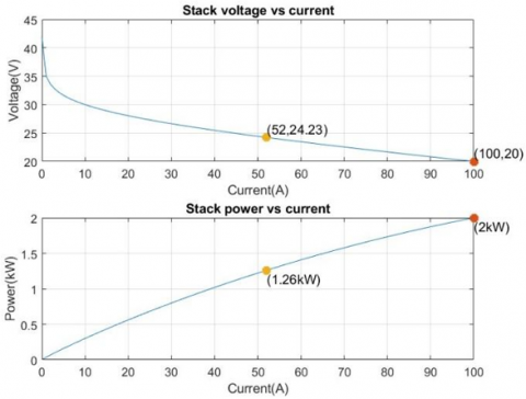
Current-voltage and power-current graphs were used to examine the PEM fuel cell stack's performance parameters. The voltage vs. current graph shows that the stack behaves like a standard PEMFC, with the voltage decreasing nonlinearly as the current rises. The highest operational point is achieved with a decreased current of 100 A, as shown in Figure 2. The voltage was constant at 20 V, while the nominal operating point was recorded at 52 A and 24.23. V. The voltage is about 42 V with the circuit open (0 A). The plot between the power and current also shows the stack. The engine may be capable of producing a current of approximately 2 kW at 100 A and a nominal power output of 1.26 kW at 52 A. It works above its designed capability at certain times. This implies that even though the model is set up as. The simulation parameters may allow for longer performance of a 1.26 kW-24 Vdc PEMFC. The total cell quantity is set to 42 instead of the conventional preset of 40. This emphasises how crucial parameter validation is when modelling the behaviour of fuel cell stacks.
Figure 2. Current vs voltage graph of a fuel cell
2.3 Results of the fuel cell
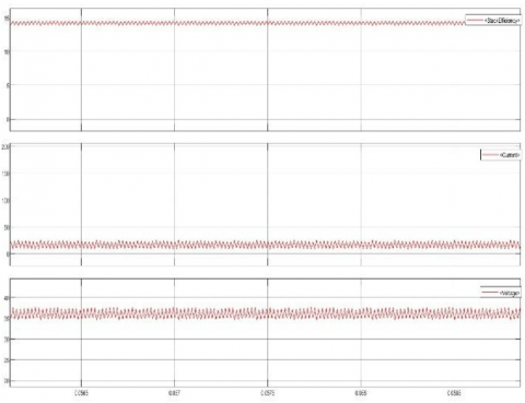
The fuel cell system simulation output presents the dynamic stack behaviour under different operating circumstances. The stack current rapidly fluctuates between 0 and 200 A in the first subplot, suggesting a cyclic or pulse-like loading behaviour. A controlled test input to assess system responsiveness or a changing load requirement could be represented by this periodic variation. The matching stack voltage, which fluctuates inversely with the current, is shown in the second subplot. The usual voltage-current characteristics of a PEM fuel cell are seen in the voltage decreasing as the current increases. To ensure operational integrity, the voltage stays between 20 and 42 volts.
The stack efficiency, as shown in Figure 3, which likewise shows recurring oscillations, is depicted in the third subplot. Since greater currents typically result in higher internal losses and lower voltage, which degrade efficiency, it is not surprising that the efficiency drops whenever the current rises. The pattern indicates that the load profile has a significant impact on the fuel cell's efficiency, highlighting the necessity of sophisticated control techniques like fuzzy logic to dynamically regulate and optimize fuel cell performance. Overall, the findings emphasize the need for real-time adaptive control and the transient nature of fuel cell operation.
Figure 3. Current, voltage, and stack efficiency of the fuel cell
The interleaved boost converter consists of multiple boost converter phases operating in parallel with phase-shifted switching signals. The operation can be classified into the following 2 modes: Mode 1 (Inductor Charging Phase): When the switch is ON, current builds up in the inductor, storing energy. Mode 2 (Inductor Discharging Phase): When the switch is OFF, the inductor releases energy to the load through the diode. The designed model has two parallel level inductors with a phase difference of 180 degrees. Interleaving Effect is the phase-shifted operation of the two inductors that ensures the total input current is more continuous, reducing ripple.
The goal of interleaved boost converter design is to improve the efficiency, stability, and reduction of input and output voltage fluctuations that characterize conventional boost converters. Using many phases (usually two or more) running in parallel with each phase interleaved—that is, having staggered switching actions—is the main characteristic of an interleaved boost converter. With the phase loading current split over several phases, this interleaving reduces overall current ripple, lowering internal component stress and enhancing output quality.
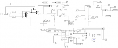
Figure 4. IBC with PID controller
Phase shift control must be carefully considered while developing the interleaved boost converter in order to guarantee ideal current distribution and reduce harmonics. In most cases, each phase has its own switch. The control method is designed to time these phases in a way that reduces the current ripple. The efficiency, size, and cost of the converter heavily depend on the inductor, switch, and controller chosen. The controller should effectively handle changes in input voltage and load conditions to maintain a steady output voltage. Additionally, because the switches generate heat, it is crucial to manage this heat to ensure proper thermal control. All things considered, the interleaved boost converter architecture improves performance in fuel cell power supplies. Figure 4 depicts IBC with a PID controller.
In order to increase a 24 V input to a 60 V output while decreasing ripple and increasing efficiency, a 2-level interleaved boost converter is used. Two parallel boost converter phases working with a 180° phase shift make up this topology, which reduces input and output current ripple.
The value of the duty cycle is calculated as given below:
D = (1 – Vin / Vout ) = 1 – (24/28) (1)
For the design of inductors, the value of the inductor ripple current is required, which is given as follows:
Δ It = Vin (1 – D) / (L * fs) (2)
The value of switching frequency is taken as 50 kHz, and the value of ripple current is obtained as 4.8 A.
The inductor values are obtained as shown below:
L = Vin (1 – D) / (fs * Δ It) = 24 * 0.6 / 100000*4.8 = 30µH (3)
The capacitor design requires the value of voltage ripple, which is calculated as shown below:
ΔV = Iout * D / (C * fs) (4)
The output ripple voltage is taken as 0.45 V, and the output current is taken as 10 A.
The value of capacitance is obtained as follows:
C = Iout * D / (fs + ΔV) (5)
The performance of the 2-level interleaved boost converter (IBC) in stepping from 24 V to 60 V while attaining increased efficiency and decreased ripple is examined using MATLAB/Simulink simulation. Two parallel boost converter phases make up the simulation model; each phase operates with a 180° phase shift to guarantee constant input current and improved power distribution. MOSFETs, diodes, inductors (50 mH each phase), and a 200 µF output capacitor are all parts of the circuit. A load resistance of 10 Ω, a 50% duty cycle, and a 50 kHz switching frequency are used.
Compared to a traditional single-phase boost converter, the simulation results show notable advantages. Because of the interleaved construction, the input current ripple is lessened, resulting in a smoother current draw and less electromagnetic interference (EMI). The output voltage stabilizes at 48 V with little fluctuation, indicating that the duty cycle regulation and capacitor selection were correct. By decreasing inductor stress and guaranteeing ripple elimination at the output, the inductor current waveforms are phase-shifted. Higher efficiency results from power loss analysis, which shows reduced conduction losses as a result of both MOSFETs' dispersed heat dissipation.
4.1 IBC with PID controller
Despite fluctuations in the load (battery charging requirements) or variations in the fuel cell's input voltage, the PID controller is in charge of keeping the interleaved boost converter's output voltage or current at a predetermined level. This is accomplished by dynamically modifying the interleaved boost converter's switches' duty cycle. The output voltage is directly impacted by the duty cycle, which establishes the ratio of time the switches are ON to OFF. The PI controller guarantees that the converter provides the battery with the appropriate voltage or current by managing the duty cycle.
The response from the PID controller's proportional term is exactly proportionate to the error between the reference value and the measured output (voltage or current).
$\mathrm{u}(\mathrm{t})=\mathrm{Kp}^* \mathrm{e}(\mathrm{t})+\mathrm{Ki} \int \mathrm{e}(\mathrm{t}) \mathrm{dt}+\mathrm{Kd} * \frac{d}{d t} \mathrm{e}(\mathrm{t}) \mathrm{dt}$ (6)
where,
Kp – Proportional Gain
Ki – Integral Gain
Kd – Derivative Gain
e(t) – error at time t
The interleaved boost converter's duty cycle is modified by this control signal u(t). The PID controller boosts the output by increasing the duty cycle if the output voltage or current falls below the reference. On the other hand, the duty cycle is decreased if the output exceeds the reference.
The PID controller in your system uses sensors to continuously check the output voltage or current. The PID controller receives the error from comparing the measured value to the reference value, or setpoint. The controller sends the correct control signal to the PWM generator after calculating the needed change in the duty cycle. This signal helps the PWM generator to power the switches in the interleaved boost converter, ensuring the output matches the intended target. The performance of the PID controller depends on selecting the right values for proportional gain (Kp), integral gain (Ki), and derivative gain (Kd). Typically, these values are adjusted through simulation, experimentation, or using methods like the Ziegler-Nichols method. Proper tuning is important to prevent issues such as overshoot, unwanted oscillations, or slow response times. This ensures stability and a quick response in the system.
4.2 IBC with FLC
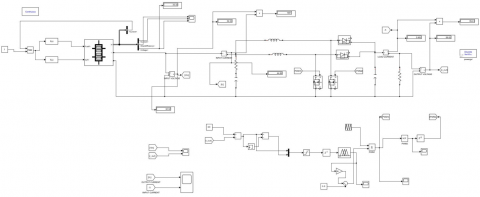
Fuzzy logic control is a type of smart system that imitates how people make choices. It works especially well in systems with complicated, nonlinear, or theoretically ill-defined dynamics. By modifying the converter's duty cycle, the fuzzy logic controller in your interleaved boost converter system controls the output voltage or current. This is accomplished by calculating the difference between the measured output and the intended reference, as well as the error's rate of change, and then using a set of preset rules to decide on the best course of action for control. Figure 5 displays IBC with FLC.
Figure 5. IBC with FLC
The controller continuously monitors the output voltage (or current) and calculates the error (e) and change in error (Δe). The act of turning precise, numerical input values—like the error and the error's rate of change into fuzzy sets is called "fuzzification." Linguistic variables like "Negative Large (NL)," "Negative Small (NS)," "Zero (Z)," "Positive Small (PS)," and "Positive Large (PL)" are mapped to these inputs. A membership function, which indicates the extent to which the input falls into a particular category, is linked to each linguistic variable.
The fuzzy logic controller's rule base, which is made up of a collection of if-then rules that specify the control strategy, is its fundamental component. These guidelines specify how the controller should react to certain input combinations and are based on system behaviour or expert knowledge. The membership values of the inputs decide how much each rule matters, and all rules are checked at the same time. Each rule gives a fuzzy set as an output, which suggests how the duty cycle should change. These rules are specified in Table 1, where "e" is the error, "e’" is the change in error, and "D" is the duty cycle.
Table 1 assigns a duty cycle control action (D) based on the output voltage error (e) and change of error (e’). Fuzzy variables for both e and e’ are a few linguistic values, viz. Negative High (NH), Negative Medium (NM), Negative Small (NS), Zero (Z), Positive Small (PS), Positive Medium (PM), and Positive High (PH). The terms define how big or small the deviation is, its direction of movement, and how fast.
The process of changing the fuzzy output into a clear number is called defuzzification. This number is important because it helps adjust the duty cycle of the interleaved boost converter. One common way to do this is the centroid method, which finds the centre of gravity for the fuzzy output set. This method ensures that the output voltage or current gets closer to what we want it to be. The duty cycle is updated with this clear number. Once updated, the duty cycle is applied to the interleaved boost converter, allowing it to operate in a way that reduces the error and aligns the output better with the desired reference.
Table 1. Fuzzy rules
|
D |
e |
|||||||
|
PH |
PM |
PS |
Z |
NS |
NM |
NH |
||
|
e` |
NH |
Z |
DNS |
DNM |
DNH |
DNH |
DNH |
DNH |
|
NM |
DPS |
Z |
DNS |
DNM |
DNH |
DNH |
DNH |
|
|
NS |
DPM |
DPS |
Z |
DNS |
DNM |
DNH |
DNH |
|
|
Z |
DPH |
DPM |
DPS |
Z |
DNS |
DNM |
DNH |
|
|
PS |
DPH |
DPH |
DPM |
DPS |
Z |
DNS |
DNM |
|
|
PM |
DPH |
DPH |
DPH |
DPM |
DPS |
Z |
DNS |
|
|
PH |
DPH |
DPH |
DPH |
DPH |
DPM |
DPS |
Z |
|
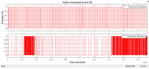
This document evaluates the performance of a 2-level interleaved boost converter as it raises the voltage from 24 V to 60 V. The focus is on achieving higher efficiency and less electrical noise, known as ripple, using a simulation done with MATLAB/Simulink as shown in Figure 6. The pulse generation for IBC with PID is shown in Figure 7. IBC with FLC simulation is depicted in Figure 8. The system has two boost converter stages working in parallel. They operate with a 180-degree phase difference. This setup ensures that the input current remains steady and power is distributed evenly. The circuit includes components like MOSFETs, diodes, and inductors, with each inductor having a value of 50 mH. It also features a 200 µF output capacitor. The system is tested with a load resistance of 10 ohms, maintains a 50% duty cycle, and has a switching frequency set at 50 kHz.
Figure 6. Simulation of IBC using PID
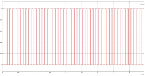
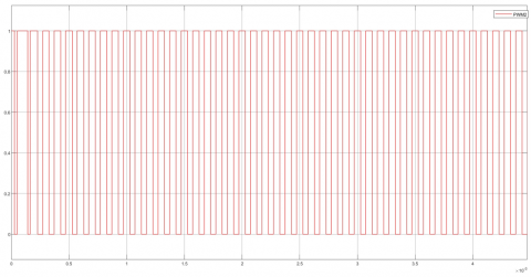
Figure 7. Pulse generation for each switch in IBC using PID
Figure 8. Simulation of IBC using FLC
When analysed alongside a conventional single-phase boost converter, the simulation demonstrates clear advantages, such as improved efficiency and performance. Because of the interleaved construction, the input current ripple is lessened, resulting in a smoother current draw and less electromagnetic interference (EMI). The output voltage stabilises at 48 V with little fluctuation, indicating that the duty cycle regulation and capacitor selection were correct. By decreasing inductor stress and guaranteeing ripple elimination at the output, the inductor current waveforms are phase-shifted. Higher efficiency results from power loss analysis, which shows reduced conduction losses as a result of both MOSFETs' dispersed heat dissipation.
To quantitatively assess efficiency impacts, thermal (conduction) losses for MOSFETs and diodes were calculated using the exact parameters from the simulation blocks. The MOSFET conduction losses were estimated using:
P_MOSFET = I² × R_on
where, R_on = 0.1 Ω as specified in the block. Internal diode losses were determined by:
P_Diode = I² × R_d + I × V_f
with R_d = 0.01 Ω and V_f = 0 V; or, for the additional diode block, R_on = 0.001 Ω and V_f = 0.8 V.
Typical loss calculations for I = 10 A yield:
Snubber network parameters were chosen to minimise additional losses, specifically R_S = 1 × 10⁵ Ω and C_S = ∞. These calculated dissipation values were used to assess total converter losses and resulting efficiency under the considered control scenarios.
Figures 9 and 10 show the 2-phase interleaved boost converter using a PID controller, while Figure 11 shows the 2-phase interleaved boost converter using a fuzzy logic controller. They can efficiently lower ripple, increase efficiency, and improve power handling capability, all of which make it appropriate for fuel cell-based applications, according to the MATLAB simulation.
Figure 9. Pulse generated for Switch 1 using FLC
Figure 10. Pulse generated for Switch 2 using FLC
Figure 11. Output voltage of the PID controller-based IBC
6.1 Simulation of IBC using PID controller
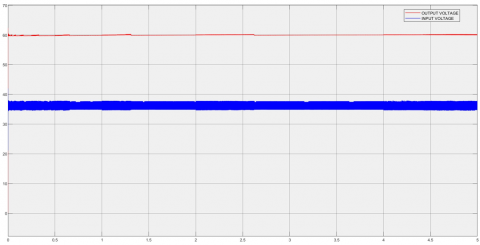
The output voltage waveform of the converter when a PID controller is used for gate pulse generation is shown in Figure 11. The output voltage waveform shows a steady, smooth DC voltage with little ripple, demonstrating the PID controller's efficient regulation. The PID controller's capacity to compensate for changes in system dynamics is demonstrated by its performance in maintaining the desired output voltage despite variations in input and load. By successfully reducing steady-state error, the controller makes sure that the output voltage closely resembles the reference value.
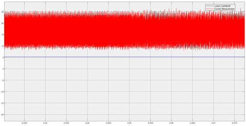
The current waveforms are shown in Figure 12. Current ripple reduction is made possible by the interleaved architecture. A steady current profile is produced by the supplementing action of the interleaved phases. It eliminates high-frequency current ripple. The outcomes demonstrate the lessened strain on the parts, which enhances the system's total effectiveness.
Figure 12. Output current of the PID controller based on IBC
6.2 Simulation of IBC using fuzzy logic controller
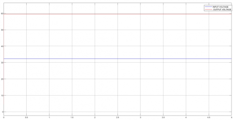
Figure 13 shows the output voltage waveform of the converter when a fuzzy-based controller is used for gate pulse generation. The output voltage is controlled by the fuzzy logic controller provides more flexibility and nonlinear control than the PID controller. This makes it especially useful for managing changing load circumstances and uncertainties. A fuzzy controller can provide reliable voltage regulation under a range of input and load situations. The generated output voltage waveform shows that in order to reduce voltage variances and ensure that the output voltage closely resembles the reference set point, the controller adjusts the duty cycle in response to system changes.
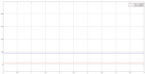
Reduced ripple current is recorded in current waveforms, as shown in Figure 14, from both the input and output stages.
Figure 13. Output voltage of FLC-based IBC
Figure 14. Output current of FLC-based IBC
Output voltage control is offered by the PID controller, a traditional linear control strategy. Good steady-state performance is achieved with low steady-state error and little output voltage ripple. Sudden changes in input or load, and it performs best in a small range of input and load situations, us taken care of by the PID controller, and it is effective to maintain a steady voltage output. It may struggle with systems that change a lot or behave nonlinearly, leading to longer times to settle and reduced efficiency. The result comparison is recorded in Table 2.
The fuzzy-based controller is designed to adjust automatically to system changes. This makes it helpful when exact mathematical models aren't available or when the system's behavior is unpredictable, uncertain, or nonlinear. The fuzzy controller for IBC offers several benefits; more precise control of the output voltage is achieved. It also manages sudden disruptions in the system in a robust way. The fuzzy controller continuously adjusts its duty cycle based on real-time conditions. Even when the load or input conditions vary, it ensures better stability, reduces overshoot, and minimises voltage fluctuations. Its ability to adapt to changing parameters means it can deliver better performance across a broader range of conditions than the PID controller.
Table 2. Comparison of results from PID and FLC
|
S. No |
Parameters |
PID |
FLC |
|
1 |
Input Voltage |
24 V |
24 V |
|
2 |
Input Current |
(10-25) A |
24 A |
|
3 |
Output Voltage |
60 V |
60 V |
|
4 |
Output Current |
5.3 A |
5.9 A |
The fuzzy-based controller is great at reducing current fluctuations. The electrical load across different phases helps to balance the current. The fuzzy controller is better because it can change its control signals to minimise rapid changes in the current even more. This results in a steadier current flow, less stress on components, and improved system efficiency. Current flow with the fuzzy controller is steady, and it lowers the risk of parts wearing out quickly or overheating, which is vital for the converter's endurance and reliability. Performance metrics comparison is recorded in Table 3.
Table 3. Performance metrics comparison
|
Characteristic |
PID Value |
FLC Value |
|
Response Time (s) |
1.2 |
0.8 |
|
Overshoot (%) |
15 |
5 |
|
Settling Time (s) |
3.5 |
2.0 |
|
Steady-State Error (%) |
2.5 |
1.0 |
|
Efficiency (%) |
85 |
92 |
|
THD (%) |
8 |
4 |
By reducing both voltage and current fluctuations, the fuzzy controller boosts the efficiency of the interleaved boost converter because it offers less energy wastage. Additionally, the fuzzy controller can adapt to different operating conditions, allowing for precise control and high-level performance. At reducing current fluctuations point of view, both controllers benefit from the interleaved boost converter.
To conclude, the fuzzy-based controller is preferred for interleaved boost converters in systems using fuel cells. Even though, PID controller handles steady voltage, it is not effective during changes in load or input voltage, which are common in fuel cell systems. The concerning issue in fuel cells is producing outputs that change in non-linear and varying ways, which can be challenging for a PID controller to manage. In contrast, the fuzzy-based controller is designed to adjust immediately and provide control to these changes effectively. It responds in real-time to input and load changes, leading to faster reaction times and more stable voltage. This adaptability minimises the risk of instability or performance issues, ensuring fuel cells operate efficiently and reliably in a certain range of conditions. In addition to that, current ripples are reduced by a fuzzy controller, a remarkable aspect in terms of fuel cell applications, where a consistent and smooth current is critical for optimal performance. This improves the efficiency of the interleaved boost converter. Ripple reduction and boosting system enhances stability, power quality, and extends the lifespan of fuel cell components, which often react to current changes. Stability, efficiency, and adaptability are enhanced by the fuzzy-based control system stands out as the best solution for fuel cell-based power systems, ensuring that the converter can dynamically respond to the evolving conditions of the fuel cell.
Future scope: Advanced fuzzy logic control techniques, such as neural network-aided tuning and adaptive fuzzy logic, offer significant improvements for DC-DC boost converters. These methods help the controller adjust automatically to changing conditions, improving performance, stability, and efficiency. They handle system nonlinearities and load variations better than traditional controllers. Implementing these advanced FLC approaches can lead to more reliable and optimised boost converter systems, especially in renewable energy and fuel cell applications. Although this work is validated through detailed simulations, future extensions will include hardware prototyping and hardware-in-the-loop (HIL) experiments to further confirm practical applicability. Future research should focus on testing these techniques in the real world.
The author expresses her thankfulness to the management for their wide-ranging facilities and support given for carrying out this research work.
The author declares that they have no known competing financial interests or personal relationships that could compromise objectivity or impartiality in a particular situation.
[1] Xu, H., Wen, X., Qiao, E., Guo, X., Kong, L. (2005). High power interleaved boost converter in fuel cell hybrid electric vehicle. In IEEE International Conference on Electric Machines and Drives, San Antonio, TX, pp. 1814-1819. https://doi.org/10.1109/IEMDC.2005.195966
[2] Samosir, A.S., Mohd Yatim, A.H. (2011). Simulation and implementation of interleaved boost DC-DC converter for fuel cell application. International Journal of Power Electronics and Drive Systems, 1(2): 168-174.
[3] Rahavi, J.A., Kanagapriya, T., Seyezhai, R. (2012). Design and analysis of interleaved boost converter for renewable energy source. In 2012 International Conference on Computing, Electronics and Electrical Technologies (ICCEET), Nagercoil, India, pp. 447-451. https://doi.org/10.1109/ICCEET.2012.6203850
[4] Nikhar, A.R., Apte, S.M., Somalwar, R. (2016). Review of various control techniques for DC-DC interleaved boost converters. In 2016 International Conference on Global Trends in Signal Processing, Information Computing and Communication (ICGTSPICC), Jalgaon, India, pp. 432-437. https://doi.org/10.1109/ICGTSPICC.2016.7955340
[5] Newlin, D.J.S., Ramalakshmi, R., Rajasekaran, S. (2013). A performance comparison of interleaved boost converter and conventional boost converter for renewable energy application. In 2013 International Conference on Green High Performance Computing (ICGHPC), Nagercoil, India, pp. 1-6. https://doi.org/10.1109/ICGHPC.2013.6533924
[6] Shenoy, K.L., Nayak, C.G., Mandi, R.P. (2017). Design and implementation of interleaved boost converter. International Journal of Engineering and Technology (IJET), 9(3S): 496-502. https://doi.org/10.21817/ijet/2017/v9i3/170903S076
[7] Seyezhai, R., Mathur, B.L. (2012). Design and implementation of interleaved boost converter for fuel cell systems. International Journal of Hydrogen Energy, 37(4): 3897-3903. https://doi.org/10.1016/j.ijhydene.2011.09.082
[8] Selvaraju, N., Shanmugham, P., Somkun, S. (2017). Two-phase interleaved boost converter using coupled inductor for fuel cell applications. Energy Procedia, 138: 199-204. https://doi.org/10.1016/j.egypro.2017.10.150
[9] Garrigos, A., Sobrino-Manzanares, F. (2015). Interleaved multi-phase and multi-switch boost converter for fuel cell applications. International Journal of Hydrogen Energy, 40(26): 8419-8432. https://doi.org/10.1016/j.ijhydene.2015.04.132
[10] Farhani, S., N'Diaye, A., Djerdir, A., Bacha, F. (2020). Design and practical study of three phase interleaved boost converter for fuel cell electric vehicle. Journal of Power Sources, 479: 228815. https://doi.org/10.1016/j.jpowsour.2020.228815
[11] Granados-Luna, T.R., Araujo-Vargas, I., Forsyth, A.J., Cano-Pulido, K., Velázquez-Elizondo, P.E., Cervantes, I., Gómez-Olguín, F., Villarruel-Parra, A. (2019). Two-phase, dual interleaved buck–boost DC–DC converter for automotive applications. IEEE Transactions on Industry Applications, 56(1): 390-402. https://doi.org/10.1109/TIA.2019.2942026
[12] Rexy, I., Mary, N., Starlin, J., Elizabeth, R. (2022). Interleaved boost converter with fuzzy logic controller. In 2022 First International Conference on Electrical, Electronics, Information and Communication Technologies (ICEEICT), Trichy, India, pp. 1-7. https://doi.org/10.1109/ICEEICT53079.2022.9768492
[13] Xu, X., Liu, W., Huang, A.Q. (2009). Two-phase interleaved critical mode PFC boost converter with closed loop interleaving strategy. IEEE Transactions on Power Electronics, 24(12): 3003-3013. https://doi.org/10.1109/TPEL.2009.2019824
[14] Slah, F., Mansour, A., Hajer, M., Faouzi, B. (2017). Analysis, modeling and implementation of an interleaved boost DC-DC converter for fuel cell used in electric vehicle. International Journal of Hydrogen Energy, 42(48): 28852-28864. https://doi.org/10.1016/j.ijhydene.2017.08.068
[15] Mauliza, Y., Indriawati, K., Wahyuono, R.A. (2022). Fuzzy logic control-based interleaved boost converter for proton exchange membrane fuel cell system applications. In 2022 International Conference on Electrical Engineering, Computer and Information Technology (ICEECIT), Jember, Indonesia, pp. 82-87. https://doi.org/10.1109/ICEECIT55908.2022.10030715
[16] Samad, M.A., Xia, Y., Manzoor, T., Mehmood, K., Saleem, A., Milyani, A.H., Azhari, A.A. (2023). Composite model predictive control for the boost converter and two-phase interleaved boost converter. Frontiers in Energy Research, 10: 1009812. https://doi.org/10.3389/fenrg.2022.1009812
[17] Hegazy, O., Van Mierlo, J., Lataire, P. (2011). Analysis, control and implementation of a high-power interleaved boost converter for fuel cell hybrid electric vehicle. International Review of Electrical Engineering, 6(4): 1739-1747.
[18] Thounthong, P., Davat, B. (2010). Study of a multiphase interleaved step-up converter for fuel cell high power applications. Energy Conversion and Management, 51(4): 826-832. https://doi.org/10.1016/j.enconman.2009.11.018
[19] Vijayalakshmi, S., Arthika, E., Priya, G.S. (2015). Modeling and simulation of interleaved Buck-boost converter with PID controller. In 2015 IEEE 9th International Conference on Intelligent Systems and Control (ISCO), Coimbatore, India, pp. 1-6. https://doi.org/10.1109/ISCO.2015.7282392
[20] Thounthong, P., Sethakul, P., Rael, S., Davat, B. (2008). Design and implementation of 2-phase interleaved boost converter for fuel cell power source. In 4th IET International Conference on Power Electronics, Machines and Drives (PEMD 2008), York, pp. 91-95. https://doi.org/10.1049/cp:20080489
[21] Gu, Y., Zhang, D. (2012). Interleaved boost converter with ripple cancellation network. IEEE Transactions on Power Electronics, 28(8): 3860-3869. https://doi.org/10.1109/TPEL.2012.2228505
[22] Wen, H., Su, B. (2016). Hybrid-mode interleaved boost converter design for fuel cell electric vehicles. Energy Conversion and Management, 122: 477-487. https://doi.org/10.1016/j.enconman.2016.06.021
[23] Choe, G.Y., Kim, J.S., Kang, H.S., Lee, B.K. (2010). An optimal design methodology of an interleaved boost converter for fuel cell applications. Journal of Electrical Engineering & Technology, 5(2): 319-328. https://doi.org/10.5370/JEET.2010.5.2.319
[24] Bahri, A., Benamrane, K., Abdelkrim, T., Bechouat, M., Mezhoud, N., Ayachi, B. (2025). Three-level boost converter with fuzzy logic for PV-battery energy systems in DC voltage control. Journal Européen des Systèmes Automatisés, 58(1): 1-12. https://doi.org/10.18280/jesa.580101
[25] Bansal, R., Bansal, R., Kumar, M. (2025). Improved reliability and performance evaluation of switched-boost multiport converter using time-multiplexing control Amélioration de la fiabilité et de l’évaluation des performances d’un convertisseur survolteur multipoint à commutation à l’aide d’une commande de multiplexage temporel. IEEE Canadian Journal of Electrical and Computer Engineering, 48(3): 167-175. https://doi.org/10.1109/ICJECE.2025.3567092