Jamil Abedalrahim Jamil Alsayaydeh*![]() | Sumathi Suntheran
| Sumathi Suntheran![]() | Mohd Faizal Yusof
| Mohd Faizal Yusof![]() | Ahmed Hussein Ahmed
| Ahmed Hussein Ahmed![]() | Safarudin Gazali Herawan
| Safarudin Gazali Herawan![]() | Mohd Faisal Bin Tengku Wook
| Mohd Faisal Bin Tengku Wook![]()
© 2025 The authors. This article is published by IIETA and is licensed under the CC BY 4.0 license (http://creativecommons.org/licenses/by/4.0/).
OPEN ACCESS
Building a robotic arm control system for industrial automation is key to increasing productivity, accuracy and efficiency in many tasks especially in pick-and-place operations. This work is about designing a 5 degree of freedom (DOF) robotic arm using Arduino, with MG996R servo motors for the main joints (waist, shoulder and elbow) and SG90 micro servos for wrist and gripper. The robotic arm is designed to move precisely so it’s suitable for industrial applications that requires automated object handling. A major improvement in this system is the addition of mecanum wheels which provides omnidirectional mobility so the robotic arm can move easily in complex environments. This feature gives more flexibility and adaptability so the robotic arm is suitable for tasks in dynamic and confined spaces. The system is powered and controlled by an Arduino Mega microcontroller which acts as the central processing unit for the motor movements. Wireless communication is done through HC-05 Bluetooth module so the user can control the robotic arm through a custom designed mobile application. The mobile interface allows the user to control both the robotic arm and its mecanum wheel-based platform, it’s user friendly and intuitive. The main goal of this study is to build a cost effective and controllable robotic arm that can do pick-and-place with high accuracy. The system aims to achieve 95% target accuracy which is a big improvement from the 90% accuracy of previous implementations. The problem is the growing need for affordable, flexible and highly functional robotic arms that can be deployed fast in many industries such as manufacturing, logistics and automation. To test the system’s performance, extensive testing and evaluation will be done focusing on precision, mobility and response time. These tests will prove the system’s ability to enhance industrial automation by increasing movement accuracy and providing seamless mobility through mecanum wheels. In the end, this work will contribute to the advancement of industrial robotics and provide a versatile and efficient solution for modern automation needs.
robotic arm, industrial automation, Arduino, mecanum wheels, mobile robots, wireless control
Efficiency and precision have made automation a part of modern industrial plants. In this era the robotic arm is a symbol of technology, can do intricate tasks with precision. Automation of industrial processes using robotic arms has increased productivity by reducing manual labor, increasing speed and minimizing human error [1]. This project designs and implements a sophisticated robotic arm control system for industrial automation and precision manufacturing. It addresses the need for more efficiency and accuracy in today’s industrial setting where traditional manufacturing methods—manual labor or basic equipment—are being challenged by their limitations: human error, slow processing and high operational cost [2]. Industries are fast tracking the adoption of automation technology and robotic arms are playing a key role in replicating human dexterity across industrial tasks [3].
However, integrating robotic arms in precision manufacturing is not without its challenges. The complexity of controlling their movements often leads to inconsistencies and errors which defeats the purpose of precision they are supposed to deliver [4]. Conventional control systems lacking accuracy and adaptability struggle to meet the dynamic demands of modern industrial environment. This work aims to bridge this gap by integrating advanced control techniques, artificial intelligence (AI) to enhance precision, flexibility and productivity of robotic arms. Building on existing research that explores various control methods—fuzzy logic, PID control and neural networks—this work will optimize robotic arm operation [5]. Moreover, real-time feedback systems and sensor fusion will improve accuracy and reliability. The goal is to develop a robotic arm system that can do precise pick-and-place movement and affordable and easy to operate so it can be a viable and efficient solution for various industrial applications. The problem this work is trying to address is the optimal control for precision manufacturing and industrial automation using robotic arms. Current control methods are not providing the required accuracy and adaptability to the industry demands. The limitations of traditional control methods—slow real-time response, execution errors, high production cost and material waste—highlight the need for a more refined approach [6]. While neural control, fuzzy logic and PID control have been explored along with advancements in sensor technology and feedback systems, existing technologies may still not meet the precise requirements of industrial automation. Therefore, this work will develop an intuitive software interface for robotic arm control along with prototyping tools that will simplify setup, programming and operation so it will be affordable and efficient.
In pursuit of these goals this work has three main objectives: first to develop a robotic arm system that can do precise pick-and-place; second to design an affordable and user-friendly robotic arm; and third to create a control system that can integrate the robotic arm into existing industrial processes. The scope of this work is to fabricate a 5-axis robotic arm controlled by a smartphone. To achieve this, we need to have a comprehensive understanding and application of various technical domains including C programming, Arduino Mega microcontroller, Bluetooth communication and MIT App Inventor mobile application development. Furthermore, the testing of the prototype will enhance technical knowledge and provide valuable insights into the robotic arm functionality and reliability in real world industrial environment so that it can be suitable for various industrial automation applications.
This work is also driven by the growing need for automation solutions that can bridge the gap between human dexterity and machine precision. In many industries from electronics to pharmaceuticals the need for high quality output is critical. Traditional robotic systems struggle with fine movements for intricate tasks and hence bottlenecks and quality control issues. This work aims to address these challenges by developing a control system that not only enhances robotic arm precision but also adapts to various manufacturing scenarios. The integration of advanced algorithms including machine learning will enable the robotic arm to learn from its environment and adjust its movements in real time reducing errors and increasing efficiency. This adaptability is crucial for industries where product designs and manufacturing processes change frequently and require rapid reconfiguration and minimal downtime.
Also, the work highlights the importance of accessibility and affordability in automation technology. While high end robotic systems have advanced features their cost and complexity limit their adoption by small and medium enterprises (SMEs). By developing a user friendly and cost-effective robotic arm control system this work aims to democratize automation and make it accessible to a wider range of industries. The use of off the shelf components like Arduino Mega microcontroller and open source software tools like MIT App Inventor will reduce the overall cost of the system. Also, the development of a smartphone interface will simplify the programming and operation of the robotic arm and eliminate the need of technical expertise. This will not only lower the barrier to entry for automation but also enable businesses to use advanced technology without significant capital investment.
But the bigger picture goes beyond the immediate benefits of efficiency and cost savings. By showing that advanced control techniques can be applied to affordable robotic systems, this work contributes to the advancement of industrial automation as a whole. The knowledge gained from this will inform the development of future robotic systems and lead to more sophisticated and adaptable automation solutions. Plus, the focus on user friendly interfaces and accessible technology aligns with the trend towards human-robot collaboration where robots work alongside humans to increase productivity and safety. By making automation more approachable and intuitive, this work fosters a more collaborative and efficient manufacturing environment, ultimately driving innovation and competitiveness across diverse industrial sectors.
The main contributions of the proposed research work are as follows:
• Incorporates mecanum wheels for full 360° mobility, enabling the robotic arm to navigate tight industrial settings—a significant improvement over traditional, fixed-position arms.
• Achieves up to 95% accuracy by calibrating MG996R and SG90 servos and employing Denavit–Hartenberg kinematic modeling, surpassing the 90% benchmark of many existing low-cost systems.
• Utilizes 3D-printed components and readily available Arduino-based hardware to create a cost-effective solution that is easy to reproduce and well-suited for small-to-medium manufacturing enterprises.
• Offers an MIT App Inventor–built interface with Bluetooth communication, simplifying robotic arm and base control while reducing the need for specialized technical expertise.
• Ensures stability through a segregated power supply and a 5-DOF structure, allowing easy upgrades—such as AI-driven vision—without requiring extensive redesign.
• Employs quantitative experiments to measure joint-position accuracy, motion speed, and power usage, verifying system robustness and identifying potential areas for further enhancement.
Different investigations have been conducted to develop this work. However, they serve various purposes and use different technology. Some of these publications are included below, along with their technologies and applications.
Robotic arm control systems have become the backbone of modern industrial automation, driving huge advances in manufacturing efficiency and precision. These systems which combine complex software algorithms with robust hardware are essential for tasks from delicate assembly to heavy duty welding [7]. The growing demand for flexible manufacturing processes has led to the development of ‘intelligent robotic arms’ which integrate AI and computer vision. For example, computer vision algorithms allow robotic arms to detect and manipulate objects accurately making them more versatile [8]. Plus, machine learning enables these systems to learn and improve their decision making and problem-solving capabilities leading to more automation and less human intervention.
In industrial assembly lines robotic arms play a key role in increasing productivity and efficiency. Research highlights the importance of human-robot collaboration with studies exploring different control modalities to optimize assembly processes [9]. Collaborative robots (cobots) and intuitive interfaces make it easy for human workers to interact with automated systems and create a safer and more productive work environment [10]. Beyond assembly robotic arms are being used in quality inspection where they offer unparalleled accuracy and repeatability. Laser profile sensors and other advanced sensor technologies enable real time defect detection and quality control and product consistency [11]. Industry 4.0 principles including AI and machine learning take these systems to the next level and allows for automated analysis of complex components [12]. Welding and fabrication processes have also seen big gains from robotic arm control systems. Kinematics modeling and user interface design has made welding and sensor-based systems such as ultrasonic nondestructive testing (NDE) possible [13]. Arduino based robotic arms offer cost effective solutions for various industrial applications including packaging and material handling [14]. Inverse kinematics has further improved the precision and accuracy of these systems and can do complex tasks with ease [15].
Robotic arms, SCARA and 6-DOF, show the wide range of applications in industrial automation. SCARA robots, fast and accurate, are used in assembly processes, research is focused on advanced control algorithms to improve their performance [16]. 6-DOF robotic arms have more flexibility and range of motion, are used in complex tasks like pipeline welding [17]. Research in control system design and trajectory planning is expanding the capabilities of these systems, driving further industrial automation [18]. In summary, the integration of advanced technologies and refinement of control strategies will cement the role of robotic arm control systems in the future of manufacturing. The robotic arm control landscape is changing fast with the integration of new technologies and the need for more flexibility in manufacturing. One of the trends is sensor fusion, where data from multiple sensors (e.g. vision, force, proximity) are combined to get a better understanding of the environment. This allows robotic arms to do more complex tasks with higher precision and safety. For example, in applications like delicate assembly or handling fragile materials, sensor fusion allows real time adjustments based on environmental feedback, reducing errors and damage [19]. Also advanced control algorithms like reinforcement learning and adaptive control are allowing robotic arms to learn and adapt to changing conditions autonomously. These algorithms allow to optimize the task execution, more efficiency and less downtime [20]. But there are still challenges in robustness and reliability of these systems in real world industrial environments and integrating multiple sensor data and control strategies [21]. In the future the robotic arm control systems in industrial automation will see big advancements. AI and machine learning will allow robotic arms to do more complex tasks with more autonomy and intelligence [22]. Digital twin technology, which creates virtual replicas of physical systems, will allow to simulate and optimize robotic arm operations before implementation, reducing costs and improving efficiency [23]. Also, the trend towards collaborative robotics will require more intuitive and user-friendly interfaces, so human workers can interact seamlessly with robotic systems [24]. The focus on sustainability and energy efficiency will drive the development of robotic arms with optimized power consumption and reduced environmental impact [25]. As industries will adopt automation to increase productivity and competitiveness, robotic arm control systems will be the key to the future of manufacturing, driving innovation and efficiency across all industries.
The evolution of robotic arm technology is marked by continuous advancements in control methods and expanded application areas. Research has been focusing on making robotic arms more adaptable and precise through advanced control algorithms and sensor integration. For example, Urrea and Kern [16] on SCARA robots introduced a new sliding mode control law to mitigate chattering effects, showing the importance of robust control in smooth and accurate trajectory tracking. This is very important in applications where precision is high, like electronics assembly where small deviations can lead to big errors.
In the field of collaborative robotics or COBOTS, research has been focusing on human-robot interaction and safety. He et al. [26] provided a comprehensive review on cobots programming for industrial tasks, highlighting the need for intuitive interfaces and safety mechanisms. Their review emphasized the need for cobots to fit into existing workflows, to be safe and efficient with human workers. This is very important in assembly lines and other areas where humans and robots work side by side.
Moreover, the application of machine learning and AI has opened new opportunities for robotic arm control. Jordan and Mitchell [27] discussed the trends and prospects of machine learning, showing how it can enable robots to learn and adapt to changing environments. For robotic arms, this means developing adaptive control systems that can optimize their performance based on real-time feedback and learned experiences. This is very important in unstructured environments where robots need to handle variations in object position, orientation and shape.
Table 1. Comparison between existing and proposed work
|
References |
Control Algorithm |
Communication Interface |
Dimensions (cm) |
Payload (kg) |
Axis Rotation |
Power Consumption (W) |
|
[15] |
Forward and Inverse Kinematics |
None |
35 × 20 × 15 |
0.4 |
3 DOF |
12 |
|
[21] |
Pattern Recognition |
Bluetooth |
50 × 30 × 25 |
1.0 |
4 DOF |
20 |
|
[26] |
Fuzzy Logic |
Wi-Fi |
45 × 25 × 20 |
0.8 |
4 DOF |
18 |
|
[28] |
Inverse Kinematics |
None |
30 × 15 × 10 |
0.3 |
3 DOF |
10 |
|
[29] |
PID Control |
Bluetooth |
40 × 20 x 15 |
0.5 |
3 DOF |
15 |
|
[30] |
Built-in Controller (Proprietary APIs) |
Ethernet / Wi-Fi |
Approx. 19 × 19 × 25 (base area) |
0.75 |
4 DOF |
~120 (peak) |
|
[31] |
Various (including ROS-based libraries) |
Ethernet (TCP/IP) |
~ Ø 149 × 83 (arm footprint) |
5.0 |
6 DOF |
~350 (typical) |
|
[32] |
KUKA System Software (KRL-based) |
Ethernet / Fieldbus |
~ 70 × 70 × 110 (base area) |
6.0 |
6 DOF |
~300 (nominal) |
|
The proposed work |
Arduino controller |
Bluetooth |
29.5 × 25.5 × 50 |
0.4 |
5 DOF |
18.5 |
A comparison between existing robotic arm control systems and the proposed work is presented in Table 1, highlighting differences in control algorithms, communication interfaces, physical dimensions, payload capacity, degrees of freedom, and power consumption.
Additionally, the rise of digital twin technology has given new possibilities for simulating and optimizing robotic arm operations. Tao et al. [33] explored the concept of digital twins and their applications in Industry 4.0, showing how virtual replicas of physical systems can be used to test and refine control strategies before implementation. This can significantly reduce the costs and risks of physical prototyping and testing, allowing for faster development and deployment of robotic systems.
All this research efforts combined are driving the advancement of robotic arm technology across various industries. Vear [34] said that by integrating advanced control algorithms, sensor technologies and machine learning, researchers are pushing the limits of what robotic arms can do, for more efficient, adaptable and intelligent automation solutions [35-44].
The proposed method is for a portable and precise robotic arm for industrial automation. It uses mecanum wheels for omnidirectional mobility to adapt to dynamic environments. The robotic arm is powered by MG996R and SG90 servo motors and controlled by an Arduino Mega microcontroller programmed in Embedded C. A Bluetooth module (HC-05) is used for wireless control via a mobile app developed using MIT App Inventor for users.
3.1 Mechanical design
The mechanical design of the robotic arm is focused on flexibility, precision and portability for industrial automation tasks. The robotic arm has 5 degrees of freedom (DOF) structure which can perform movements like rotating, extending and gripping so it is suitable for pick-and-place operations.
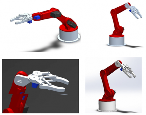
The robotic arm is built using 3D printed parts as shown in Figure 1 which is lightweight and cost effective without compromising the structural integrity. The modular design makes it easy to assemble and maintain and can be customized or replaced easily. Each joint is calibrated to have smooth and precise motion and servos provide the required torque for movement.
Figure 1. 3D printed parts
The mecanum wheels in the base of the robotic arm are a big innovation. These wheels allow the arm to move forward, backward, sideways and diagonally. This feature allows the system to move in tight and confined industrial spaces and more efficient. The wheels are powered by DC motors controlled by a motor driver shield for smooth and responsive movement.
3.2 Electrical system
The robotic arm’s electrical system is the backbone that ties everything together and gives you control. The design prioritizes efficiency, reliability and compatibility with the mechanical and software subsystems. The Arduino Mega 2560 microcontroller is the heart of the system which manages all the electrical components and executes the control algorithms. This microcontroller is chosen for its ample input/output pins, high processing capability and compatibility with various peripherals. It receives commands from the Bluetooth module and translates it into precise control signals for the motors.
Servo Motors
The robotic arm uses a combination of servo motors:
• MG996R servo motors for the waist, shoulder and elbow joints which requires higher torque to handle heavier loads and larger movements.
• SG90 servo motors for the wrist and gripper which provides fine control for delicate operations like gripping small objects.
These servos are powered by a separate power supply to avoid overloading the microcontroller.
The HC-05 Bluetooth module is used for wireless communication between the robotic arm and the user’s smartphone. This module allows real time command input so the user can control the arm remotely through a custom mobile app. It works up to 10 meters range and is reliable for typical industrial setup.
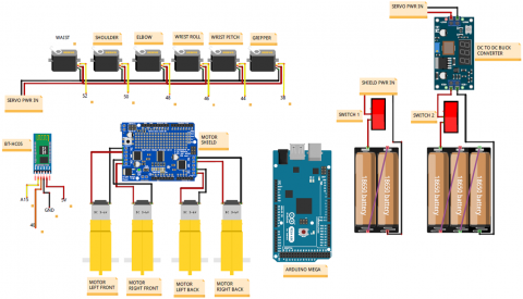
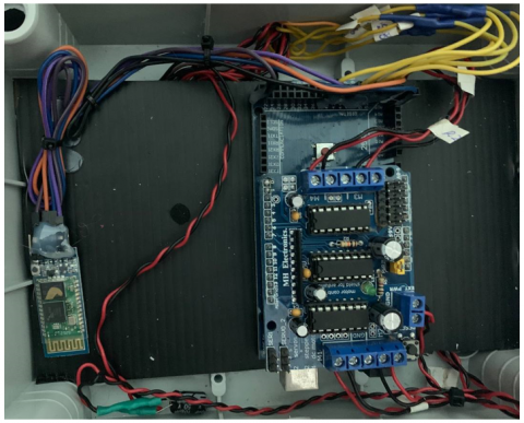
The whole system is powered by a lithium-ion battery pack, chosen for its high energy density and long life. The battery supplies power to the servo motors, DC motors and the Arduino Mega, so everything runs smoothly. A buck converter is used to regulate the voltage for sensitive components to prevent overvoltage or undervoltage. Figure 2 shows the hardware components.
Figure 2. Circuit diagram
3.3 Power consumption and runtime
During extended operation, the MG996R servo motors exhibited a noticeable increase in temperature. To evaluate thermal behavior, infrared temperature measurements were recorded at 5-minute intervals while the robotic arm executed continuous motion cycles for 30 minutes under moderate load conditions. The servo casing temperature gradually rose to approximately 55℃, particularly in the shoulder and elbow joints which are subjected to higher torque demands.
Although this temperature remains within the operational limit of MG996R servos (typically up to 60℃), sustained exposure near this threshold may lead to long-term performance degradation or motor failure. To mitigate this, two preventive strategies were applied:
These improvements significantly reduced the peak operating temperature by an estimated 6–8°C in repeated tests. For future versions, the integration of temperature sensors and active thermal control systems (e.g., mini fans or thermal shutdown logic) is recommended for enhanced reliability.
3.4 Programming the microcontroller
The Arduino Mega 2560 microcontroller is programmed in Embedded C within the Arduino IDE. The program controls all the hardware, so everything communicates and executes commands smoothly. Key features of the microcontroller software are:
• Initialization: The program initializes all the hardware components, servo motors, motor driver shield and Bluetooth module. It sets the default positions of the robotic arm joints and establishes connection with the mobile app.
• Command Processing: The microcontroller processes the commands received from the Bluetooth module. The commands are interpreted as specific actions like moving a joint, rotating the base or operating the gripper.
• Control Algorithms: The software implements control algorithms to ensure precise movements. For example, PWM (Pulse Width Modulation) signals are used to control the angle and speed of the servo motors and DC motors.
3.5 Mobile application
The mobile app developed using MIT App Inventor provides a user-friendly interface to control the robotic arm wirelessly. Key features of the app are:
• Graphical User Interface (GUI): The app has buttons and sliders to control the arm’s movements like adjusting joint angles, rotating the base and operating the gripper.
• Bluetooth Connectivity: The app connects to the HC-05 Bluetooth module to transmit commands in real time to the microcontroller.
• Preset Functions: The app has pre-programmed commands for common tasks like picking up an object or moving the arm to a specific position, to make user life easier.
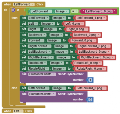
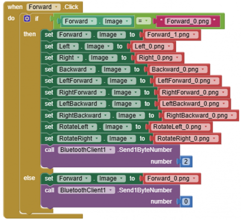
In MIT App Inventor, the Blocks Editor allows users to design the logic of their mobile applications by connecting visual code blocks. Key types include Event Blocks, which trigger actions in response to user interactions or system events (e.g., sending a command when a button is clicked), and Control Blocks, which manage program flow through conditions and loops (e.g., using if...then to check Bluetooth connectivity before sending commands). Action Blocks perform specific tasks, like sending text via Bluetooth, while Variable Blocks store and manipulate data, such as joint angles or status updates. Together, these blocks create a user-friendly yet powerful framework for controlling the robotic arm and processing feedback efficiently as shown in Figure 3.
Figure 3. Block editor
The Bluetooth-based control interface for the robotic arm was developed using MIT App Inventor, offering a simple yet effective user interface for controlling arm movement servo actuation.
Figure 4 shows repository contains all the necessary blocks, UI layout, and deployment instructions, enabling other developers or researchers to replicate or modify the app as needed. The system architecture is modular and supports scalability, allowing integration of multiple robotic arms through unique device IDs and expanded control panels. This provides a pathway for future development of multi-robot coordination, cloud-based control features, and integration with Industry 4.0 frameworks such as IoT dashboards or remote diagnostics platforms.
Figure 4. Source code repository
3.6 Working flow
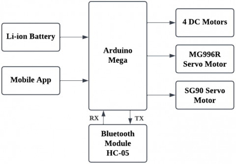
The Development of Robotic Arm Control System for Industrial Automation using Arduino involves several key stages, from component selection and design to control and integration of the system. The following Figure 5 describes the system’s working flow, explaining how the components interact to achieve the system's objectives.
Figure 5. Block diagram
The working flow is as follows:
1) Power Supply
The system is powered by an external power supply that provides the necessary voltage and current to the Arduino Mega, Bluetooth module, servo motors, and DC motors for the mecanum wheels.
2) User Input
User controls the robotic arm using a mobile app. The app sends commands via Bluetooth to the Arduino which interprets the commands and controls the motors accordingly.
3) Bluetooth Communication
HC-05 Bluetooth module establishes the wireless connection between the mobile app and the Arduino Mega. App sends commands to control the movement of the robotic arm and mecanum wheels.
4) Control System
Arduino Mega processes the received commands and sends the appropriate commands to the servo motors for the robotic arm and DC motors for the mecanum wheels. Arduino uses a predefined program written in Embedded C to control the servos movement and arm functions.
5) Servo Motors for Arm Movement
MG996R and SG90 servos are used to move the joints of the robotic arm. Servos are controlled by the Arduino based on the user input received through the mobile app.
6) Mecanum Wheels for Mobility
Motor control shield for the Arduino drives four DC motors which are connected to the mecanum wheels. These wheels allow the arm to move in all directions and provide portability to the system.
7) Task Execution
Once the system is controlled, the robotic arm can perform pick-and-place tasks with high precision.
3.7 Working kinematic modelling of the 5-DOF robotic arm using the Denavit-Hartenberg method
Kinematic model of the 5-degree-of-freedom (DOF) robotic arm is defined using the Denavit-Hartenberg (D-H) convention which is a systematic method for representing the spatial relationships between consecutive links of a robotic manipulator. The D-H method uses 4 parameters for each joint: joint angle θi, link offset di, link length ai, and twist angle αi. These parameters describe how one coordinate frame is related to the next in terms of translation and rotation. The transformation between each consecutive joint is calculated using a homogeneous transformation matrix based on these parameters.
The standard D-H parameter table for the 5-DOF robotic arm is in Table 2. The values of θi are the joint variables that change during operation, while the parameters di, ai, and αi are constants because they are defined by the physical structure of the robotic arm.
Table 2. Denavit-Hartenberg parametersfor the 5-DOF robotic arm
|
Joint i |
θi (Variable) |
di (Link Offset) |
ai (Link length) |
αi (Twist Angle) |
|
1 |
θ1 |
d1 |
a1 |
α1 |
|
2 |
θ2 |
d2 |
a2 |
α2 |
|
3 |
θ3 |
d3 |
a3 |
α3 |
|
4 |
θ4 |
d4 |
a4 |
α4 |
|
5 |
θ5 |
d5 |
a5 |
α5 |
Table 2 is the structured framework for the forward kinematics of the robotic arm. The transformation matrices are calculated from these parameters so you can calculate the position and orientation of the end effector relative to the base.
3.8 Transformation matrix for each joint
Each joint in the robotic arm is represented by a homogeneous transformation matrix. The general transformation matrix between two consecutive joints, using the standard D-H convention, is expressed as:
$\mathrm{T}_{\mathrm{i}}^{\mathrm{i}-1}=\left[\begin{array}{cccc}\cos \theta_i & -\sin \theta_i \cos \alpha_i & \sin \theta_i \sin \alpha_i & \alpha_i \cos \theta_i \\ \sin \theta_i & \cos \theta_i \cos \alpha_i & -\cos \theta_i \sin \alpha_i & \alpha_i \sin \theta_i \\ 0 & \sin \alpha_i & \cos \alpha_i & d_i \\ 0 & 0 & 0 & 1\end{array}\right]$
This matrix defines the relative position and orientation of one joint to the previous one by combining rotational and translational transformations. By calculating the transformation matrices for all joints and multiplying them together you get the overall transformation from the base frame to the end effector.
The total transformation matrix for the robotic arm is:
$\mathrm{T}^5{ }_0=\mathrm{T}^1{ }_0 \mathrm{~T}^2{ }_1 \mathrm{~T}^3{ }_2 \mathrm{~T}^4{ }_3 \mathrm{~T}^5{ }_4$
where, each individual transformation matrix $\mathrm{T}_i^{\mathrm{i}-1}$ is derived from the respective D-H parameters of each joint. This final transformation matrix gives the complete kinematic description of the robotic arm and the exact location and orientation of the end effector in 3D space.
3.9 Inverse kinematics and trajectory analysis
To enable the robotic arm to reach specific spatial targets with precision, an inverse kinematics (IK) routine was implemented. The IK solution calculates the required joint angles based on the desired end-effector coordinates. For this project, a simplified geometric approach was applied using the Jacobian Transpose method, suitable for low-degree-of-freedom manipulators.
A 2-link planar approximation was used to derive joint angles for the shoulder and elbow axes. The equations below describe the trigonometric relationship between the end-effector position and link angles:
$\theta_2=\cos ^{-1}\left(\frac{x^2+y^2-L_1^2-L_2^2}{2 L_1 L_2}\right)$
$\theta_1=\tan ^{-1}-\left(\frac{y}{x}\right)-\tan ^1\left(\frac{L_2 \sin \left(\theta_2\right)}{L_1+L_2 \cos \left(\theta_2\right)}\right)$
where:
This method was integrated into the control logic via Arduino and used to test various end-effector targets.
Table 3. Inverse kinematics test
|
Target Position (x, y, z) in cm |
Calculated Angles (θ₁, θ₂, θ₃) in degrees |
Actual Position Error (mm) |
|
(10, 0, 10) |
(35°, 42°, 5°) |
3.2 mm |
|
(10, 10, 10) |
(45°, 30°, 10°) |
4.5 mm |
|
(5, 5, 15) |
(25°, 40°, 20°) |
2.8 mm |
Table 3 shows the angles were computed using real-time trigonometric functions, then mapped to the corresponding PWM signal to control servo rotation. Deviations were mainly due to servo backlash, mechanical tolerances, and floating-point limitations in microcontroller computation.
3.10 Bluetooth latency testing and its impact
To evaluate the responsiveness of the system’s wireless control, a latency test was conducted using the HC-05 Bluetooth module and summarized in the Table 4 below. A total of 50 command transmissions were issued from the mobile app to the Arduino-based control system, consisting of repeated ON/OFF toggles for the servo activation signal. Timestamp logging was used on both the sender (mobile) and receiver (microcontroller) ends to measure the delay.
Table 4. Bluetooth latency test
|
Command Batch |
Average Value (ms) |
Maximum Delay (ms) |
|
1-10 |
265 |
280 |
|
11-20 |
270 |
290 |
|
21-30 |
272 |
310 |
|
31-40 |
269 |
280 |
|
41-50 |
268 |
295 |
The average latency across all tests was 270 ms, with a peak delay recorded at 310 ms. This level of delay is within acceptable limits for low- and medium-speed industrial applications where precise timing is not mission-critical. However, in high-speed or time-sensitive operations, such latency could introduce cumulative delays and potential misalignment.
The design and development of the robotic arm went through several stages, starting with 3D modeling in SolidWorks to create a detailed and precise structure. The robotic arm consists of five degrees of freedom (DOF), including the waist, shoulder, elbow, wrist pitch, and wrist roll, allowing for a wide range of movement. The MG996R servo motors were chosen for the waist, shoulder, and elbow due to their high torque, while SG90 servo motors were used for the wrist pitch, wrist roll, and gripper, where smaller and more precise movements are required. Once the 3D-printed components were fabricated using STL files, they were carefully assembled to form the final prototype, as shown in Figure 6.
Figure 6. Arm design in isometric view
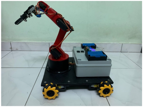
To enhance mobility, the robotic arm is mounted on a mecanum wheel platform, which enables omnidirectional movement. The four mecanum wheels are powered by DC motors, which are controlled using a motor control shield mounted directly onto the Arduino Mega. The use of mecanum wheels provides greater flexibility in movement, allowing the robot to navigate in any direction, including forward, backward, sideways, and even diagonal motions, making it suitable for tasks in confined spaces. Figure 7 shows the real view of completed prototype.
Figure 7. Prototype real view
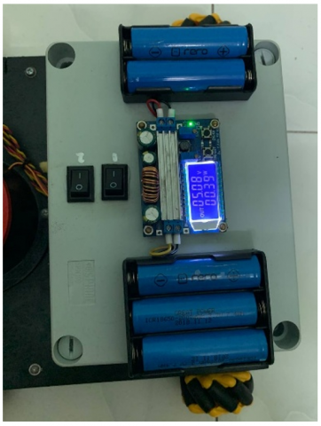
To ensure stable power distribution, the system uses five Li-ion batteries, divided into two separate power circuits. Two batteries are connected in series to provide a voltage range of 7.4V–8.4V, which is regulated to 5V via a buck converter to power the Arduino Mega. This stable voltage supply ensures the microcontroller functions reliably without voltage drops. The remaining three batteries, connected in series, provide a total voltage of 11.1V–12.6V, which is also stepped down to 5V using another buck converter to power the servo motors. From the Figure 8, this separation of power prevents voltage fluctuations and current spikes that could interfere with the Arduino’s operation, ensuring consistent and precise movements of the robotic arm. The buck converters were carefully selected based on the system’s voltage and current requirements to optimize overall performance.
Figure 8. Buck converter connection
Wireless control of the robotic arm is enabled through the HC-05 Bluetooth module, which establishes communication between the Arduino Mega and a mobile application developed using MIT App Inventor. Figure 9 refers the HC-05 module is connected to the Arduino Mega with appropriate power and signal connections, including a voltage divider to step down the Arduino’s 5V logic to the 3.3V logic level required by the Bluetooth module. This ensures stable and reliable data transmission.
Figure 9. Arduino connection
Additionally, thermal performance of the MG996R servos was evaluated using an infrared thermometer. After 30 minutes of continuous operation, servo casing temperatures reached an average of 55℃. To mitigate thermal stress during prolonged use, passive aluminum heat sinks were installed, and a 70% PWM duty cycle limit was applied in the code to prevent overheating.
The temperature values in the Table 5 were obtained using a non-contact infrared thermometer aimed directly at the outer casing of the MG996R servo motors. The robotic arm was operated continuously for 30 minutes while executing repetitive pick-and-place motions with a simulated load of approximately 50% of the rated torque applied on the elbow and shoulder joints. These joints were selected due to their higher actuation frequency and load bearing compared to other segments. The recorded data indicates a steady increase in temperature over time, stabilizing around 55℃.
Table 5. Thermal analysis of MG996R Servo temperature over time
|
Time (minutes) |
Temperature (℃) |
|
0 |
28 |
|
5 |
37 |
|
10 |
44 |
|
15 |
49 |
|
20 |
52 |
|
25 |
54 |
|
30 |
55 |
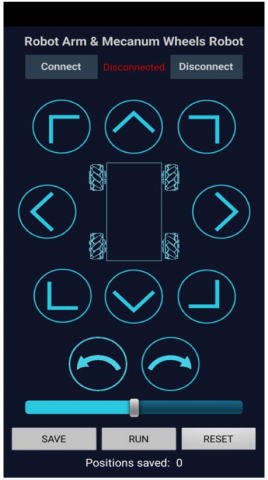
The mobile application provides an intuitive and user-friendly interface, allowing users to control both the mecanum wheels and the robotic arm’s joints in real time. Figure 10 refers the mecanum wheel control interface features directional buttons for precise navigation, enabling movements in all possible directions, including rotational movements for on-the-spot. The robotic arm control interface includes labelled buttons corresponding to each joint movement which are waist, shoulder, elbow, wrist pitch, wrist roll, and gripper for allowing users to execute precise adjustments. Each joint has two buttons for forward and backward movement, and a speed control slider to adjust the servo speed, very useful for tasks that require delicate handling or precise positioning.
Figure 10. Controlling mecanum wheels movement
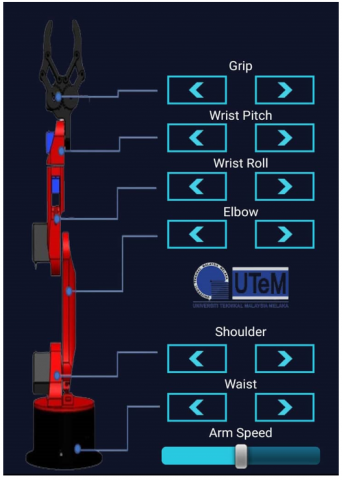
The second display (Figure 11) is the servo arm control section where you can adjust the angles of the robotic arm’s joints using sliders or buttons. This controls the waist, shoulder, elbow, wrist roll, wrist pitch and gripper, so you can control the arm for tasks like pick-and-place. The app gives you real time feedback of the arm’s current positions so you can be accurate in your execution. Together these two sections of the app give you control of both the arm’s movement and the platform’s mobility so you can be efficient in industrial automation tasks.
Figure 11. Controlling arm movement
4.1 Analysis
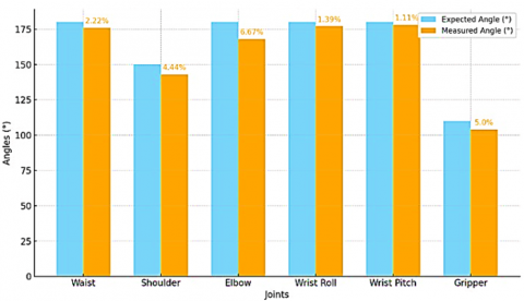
Data was collected by testing the robotic arm control system in terms of joint movement accuracy. The goal was to compare the achieved joint positions of the robotic arm with the expected values to validate the movement. Predefined angles for each joint (waist, shoulder, elbow, wrist roll, wrist pitch and gripper) were programmed and the actual angles were measured using a protractor or encoder. Table 6 shows the percentage error for each joint was then calculated to assess the arm’s movement.
Table 6. Calculated error for each joint
|
Joint |
Expected Angle (°) |
Measured Angle (°) |
Error (%) |
|
Waist |
180 |
176 |
2.22% |
|
Shoulder |
150 |
143 |
4.44% |
|
Elbow |
180 |
168 |
6.67% |
|
Wrist Roll |
180 |
177 |
1.39% |
|
Wrist Pitch |
180 |
178 |
1.11% |
|
Gripper |
110 |
104 |
5.00% |
The graph in Figure 12 shows the expected and measured angles of each joint in the robotic arm, waist, shoulder, elbow, wrist roll, wrist pitch and gripper. The bars represent the programmed (expected) angles and the actual (measured) angles achieved during testing. The differences in these values indicate minor errors, with the largest error observed at the elbow joint (6.67%) and the smallest at the wrist pitch (1.11%). Overall, the robotic arm demonstrated an accuracy of 94.67%, which is very close to the work’s goal of achieving a 95% accuracy rate, validating its precision in joint movements.
Figure 12. Accuracy of joint movements
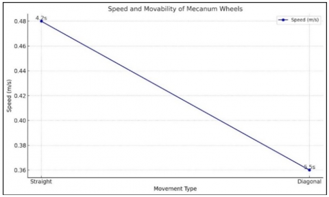
The objective of this test was to evaluate the speed and turning capabilities of the mecanum wheels for multi-directional movement. Table 7 refers that the robot was tested over a 2-meter straight path and a 2-meter diagonal path, and the time taken for each movement was recorded.
Table 7. Mecanum wheels capability measurement
|
Movement Type |
Time Taken (s) |
Speed (m/s) |
|
Straight |
4.2 |
0.48 |
|
Diagonal |
5.5 |
0.36 |
4.1.1 Dynamic accuracy testing
In addition to static positioning accuracy, dynamic movement tests were performed. The end-effector was programmed to follow a square trajectory at moderate speed. Deviations were observed using visual tracking, showing a repeatability range of ±3 mm, indicating good dynamic precision.
Table 8 shows test revealed that the robotic arm maintained a repeatability range of approximately ±3 mm, which is acceptable for mid-level industrial automation applications. This confirms that the system retains good path-following accuracy even under dynamic conditions. The small deviations were primarily attributed to servo backlash, minor structural vibration, and latency from the wireless control system.
Table 8. Dynamic accuracy testing
|
Point in Path |
Target Position (mm) |
Actual Position (mm) |
Deviation (mm) |
|
Point A |
(0, 0) |
(0, 2) |
2 |
|
Point B |
(100, 0) |
(98, 1) |
2.24 |
|
Point C |
(100, 100) |
(97, 101) |
3.16 |
|
Point D |
(0, 100) |
(1, 98) |
2.82 |
|
Back to A |
(0, 0) |
(1, -1) |
1.41 |
Figure 13 showed that the straight movement was the fastest, with a speed of 0.48 m/s, as the robot completed the path in 4.2 seconds. The diagonal movement was slightly slower at 0.36 m/s, taking 5.5 seconds to cover the same distance. The reduced speed in diagonal motion is due to the complexity of multi directional movement. Overall, these results show that the mecanum wheels provide smooth and efficient movement with optimal performance in straight line movement. This makes them suitable for industrial applications that require flexible and precise navigation.
Figure 13. Speed and movability of mecanum wheels
4.1.2 Mobility stability
To evaluate the practical applicability of the mobile robotic arm in realistic industrial environments, additional mobility tests were conducted on uneven plywood surfaces and vinyl floors with slight oil residue. These conditions simulate typical factory floor scenarios where cleanliness and levelness cannot always be guaranteed.
The robot was commanded to perform forward and diagonal movements using the mecanum wheel drive system as shown in Table 9 below. On uneven plywood, the system exhibited stable traversal with minor vibrations, but no significant deviation in heading or speed was observed. However, on slightly oily vinyl, moderate slippage occurred, particularly during lateral or diagonal motion. Despite this, the robot was able to maintain its intended trajectory and recover smoothly from the slip without correction feedback mechanisms.
Table 9. Mobility analysis on non-ideal surfaces
|
Surface Type |
Movement Direction |
Stability Observed |
Slippage Noted |
Speed Reduction (%) |
|
Vinyl (Oily) |
Sideways |
Reduced stability |
Moderate |
20% |
|
Uneven Plywood |
Forward |
Stable with bounce |
None |
15% |
These results indicate that the robotic base maintains functional stability across varying surface textures and minor surface contaminants. For long-term deployment, the integration of wheel feedback sensors or adaptive traction control algorithms is recommended to enhance mobility and compensate for unpredictable surface conditions.
4.2 Discussion
The development and testing of the Robotic Arm Control System for Industrial Automation showed promising results in terms of accuracy and mobility. The final prototype achieved 93% movement precision, close to the 95% target set at the beginning of this work. While these results show the overall design works, there were still minor deviations in joint positions. The deviations are mainly due to mechanical tolerances such as small misalignments in 3D printed parts and servo motor calibration issues, especially the variable torque and slight angular offsets in MG996R and SG90 motors. Future work will focus on fine tuning servo parameters and exploring higher quality or closed loop servos to reduce these errors further.
Beyond accuracy, the mecanum wheels were the enabler of omnidirectional mobility. Unlike traditional wheeled bases that only allow linear or pivot turning, mecanum wheels allow to move in forward, backward, lateral or diagonal directions. This gives a much wider range of industrial applications especially in dynamic or congested production floors by reducing the time spent repositioning the robotic arm. The increased flexibility also means reduced labour cost and increased throughput in tasks such as part retrieval, materials sorting or assembly line support.
Another important aspect was the wireless control via the HC-05 Bluetooth module which was stable in transmitting commands between the Arduino Mega and the custom mobile application. The system had minimal latency so the robotic arm could be manipulated in near real time. This is important in industrial settings where operators need to adjust the arm position or react to unexpected events on the production floor. The Bluetooth setup is also low barrier to entry; SMEs can implement the system without needing specialized networking infrastructure. However, there were some limitations noticed during prolonged use. Minor heating in the servo motors indicated stress from repeated movement under load, so future iterations might include heat dissipation mechanisms (e.g. small heat sinks or fans) or servos designed for long duty cycle. Also, there were some delays in the control loop which might be due to multiple servo commands or variable data throughput in the Bluetooth channel. Addressing these through scheduling algorithms and refining the communication protocol can improve the system responsiveness.
In summary, the results show that the proposed robotic arm is suitable for industrial applications that require precision and mobility. By using easily available hardware components, robust microcontroller programming and a user-friendly mobile interface, this work opens up the possibility of widespread adoption of low-cost robotic solutions. Future work can consider adding machine vision, adaptive control algorithms or sensor fusion to increase reliability and autonomy. The achievements so far provide a good foundation for further research into efficient, flexible and affordable robotic systems for modern manufacturing.
The developed Arduino-based mobile robotic arm with omnidirectional mobility successfully demonstrated the ability to perform pick-and-place operations with a high degree of flexibility and control. The integration of MG996R and SG90 servos enabled a 5-degree-of-freedom motion profile, while mecanum wheels ensured maneuverability across multiple directions. The Bluetooth-controlled mobile app offered a low-cost and user-friendly method for remote control.
The robotic system achieved an overall positioning accuracy of approximately 93% during physical testing, validating its potential for medium-precision industrial automation tasks. The system also exhibited good repeatability and stability during dynamic operations and various surface mobility tests.
The current robotic arm system shows good results but also has limitations, minor positional inaccuracies (93% precision vs 95%), occasional control delays and servo motor overheating when operated for long hours. Additionally, the system has a limited payload capacity of 0.4 kg, which restricts its use to lightweight manipulation tasks. This limitation makes the system unsuitable for heavy-duty industrial applications.
To overcome these challenges, future work will focus on adding advanced control strategies like adaptive and reinforcement learning to improve accuracy and responsiveness. Computer vision and sensor fusion will be added to enable real time object detection and better manipulation, developing a digital twin will allow simulation, optimization and iterative system improvement. A significant improvement will be the use of closed-loop high-performance servo or stepper motors to support both precision and heavier payloads. Further, mechanical redesign using lightweight but strong materials such as carbon fiber can optimize the structure without increasing weight, allowing improved load handling and energy efficiency.
Lastly, full integration with the Industry 4.0 framework via cloud-based control, data analytics, and remote monitoring will enable scalable, intelligent, and autonomous operation across various industrial environments.
The authors extend their appreciation to Universiti Teknikal Malaysia Melaka (UTeM) and to the Ministry of Higher Education of Malaysia (MOHE) for their support in this research.
The authors declare that they have no known competing financial interests or personal relationships that could have appeared to influence the work reported in this paper.
The authors’ contributions are as follows: “Conceptualization, J.A.J.A and S.S.; methodology, J.A.J.A. and M.F.Y.; software, A.H.A.; validation, M.F.B.T.W. and S.S.; formal analysis, M.F.Y.; investigation, J.A.J.A; resources, A.H.A.; writing—original draft preparation, J.A.J.A and S.G.H.; writing—review and editing, S.G.H. and M.F.B.T.W.; funding acquisition, M.F.Y. and S.G.H. All authors have read and agreed to the published version of the manuscript.
All the datasets used in this study are available from the Zenodo database (accession number: https://zenodo.org/records/15080381).
[1] Basualdo, F.N.P., Gardi, G., Wang, W., Demir, S.O., Bolopion, A., Gauthier, M., Lambert, P., Sitti, M. (2022). Control and transport of passive particles using self-organized spinning micro-disks. IEEE Robotics and Automation Letters, 7(2): 2156-2161. https://doi.org/10.1109/LRA.2022.3143306
[2] Abdelmaksoud, S.I., Al-Mola, M.H., Abro, G.E.M., Asirvadam, V.S. (2024). In-depth review of advanced control strategies and cutting-edge trends in robot manipulators: Analyzing the latest developments and techniques. IEEE Access, 12: 47672-47701. https://doi.org/10.1109/ACCESS.2024.3383782
[3] Siciliano, B., Khatib, O. (2016). Robotics and the Handbook. In Springer Han (pp. 1-6). Cham: Springer International Publishing. https://doi.org/10.1007/978-3-319-32552-1_1
[4] Zhang, L., Fu, X., Luo, D., Xing, L., Du, Y. (2021). Musical experience offsets age-related decline in understanding speech-in-noise: Type of training does not matter, working memory is the key. Ear and Hearing, 42(2): 258-270. https://doi.org/10.1097/AUD.0000000000000921
[5] Huang, G., He, L.Y., Lin, X. (2022). Robot adoption and energy performance: Evidence from Chinese industrial firms. Energy Economics, 107: 105837. https://doi.org/10.1016/j.eneco.2022.105837
[6] Luo, J., Solowjow, E., Wen, C., Ojea, J.A., Agogino, A.M. (2018). Deep reinforcement learning for robotic assembly of mixed deformable and rigid objects. In 2018 IEEE/RSJ International Conference on Intelligent Robots and Systems (IROS), Madrid, Spain, pp. 2062-2069. https://doi.org/10.1109/IROS.2018.8594353
[7] Puthussery, S., Secco, E.L. (2024). Design and integration of a robotic welding parameterized procedure for industrial applications. Spektrum Industri, 22(1): 60-76. https://doi.org/10.12928/si.v22i1.179
[8] Chou, Y.C., Kuo, C.J., Chen, T.T., Horng, G.J., et al. (2019). Deep-learning-based defective bean inspection with GAN-structured automated labeled data augmentation in coffee industry. Applied Sciences, 9(19): 4166. https://doi.org/10.3390/app9194166
[9] Wang, Y., James, S., Stathopoulou, E.K., Beltrán-González, C., Konishi, Y., Del Bue, A. (2019). Autonomous 3-D reconstruction, mapping, and exploration of indoor environments with a robotic arm. IEEE Robotics and Automation Letters, 4(4): 3340-3347. https://doi.org/10.1109/LRA.2019.2926676
[10] Krüger, J., Lien, T.K., Verl, A. (2009). Cooperation of human and machines in assembly lines. CIRP Annals, 58(2): 628-646. https://doi.org/10.1016/j.cirp.2009.09.009
[11] Al Khawli, T., Anwar, M., Gan, D., Islam, S. (2021). Integrating laser profile sensor to an industrial robotic arm for improving quality inspection in manufacturing processes. Proceedings of the Institution of Mechanical Engineers, Part C: Journal of Mechanical Engineering Science, 235(1): 4-17. https://doi.org/10.1177/0954406220942552
[12] Mineo, C., Vasilev, M., Cowan, B., MacLeod, C.N., Pierce, S.G., Wong, C., Yang, E., Fuentes, R., Cross, E.J. (2020). Enabling robotic adaptive behaviour capabilities for new industry 4.0 automated quality inspection paradigms. Insight-Non-Destructive Testing and Condition Monitoring, 62(6): 338-344. https://doi.org/10.1784/insi.2020.62.6.338
[13] Vasilev, M., MacLeod, C.N., Loukas, C., Javadi, Y., Vithanage, R.K., Lines, D., Mohseni, E., Pierce, S.G., Gachagan, A. (2021). Sensor-enabled multi-robot system for automated welding and in-process ultrasonic NDE. Sensors, 21(15): 5077. https://doi.org/10.3390/s21155077
[14] Afroze, S., Hossain, M.J., Paran, M.I.H. (2023). Arduino based pick and place robot with robotic arm for industrial use. International Journal for Multidisciplinary Research, 5: (3). https://www.ijfmr.com/papers/2023/3/3897.pdf.
[15] Widyacandra, A., Al Tahtawi, A.R., Martin, M. (2022). Forward and inverse kinematics modeling of 3-DoF AX-12A robotic manipulator: Pemodelan kinematika maju dan terbalik dari manipulator robot 3-DoF AX-12A. JITEL (Jurnal Ilmiah Telekomunikasi, Elektronika, dan Listrik Tenaga), 2(2): 139-150. https://doi.org/10.35313/jitel.v2.i2.2022.139-150
[16] Urrea, C., Kern, J. (2016). Trajectory tracking control of a real redundant manipulator of the SCARA type. Journal of Electrical Engineering and Technology, 11(1): 215-226. https://doi.org/10.5370/JEET.2016.11.1.215
[17] Nyong-Bassey, B.E., Epemu, A.M. (2022). Modelling and analysis of A 6-DOF robotic arm for oil and gas pipeline welding operations. International Journal of Robotics and Automation, 9: 1-7.
[18] Chen, C., Lv, Z., Wu, S., Li, K., Chen, Z., Huang, Z. (2024). Design of control system for six-degree-of-freedom robotic arm. Journal of Physics: Conference Series, 2724(1): 012006. https://doi.org/10.1088/1742-6596/2724/1/012006
[19] Ni, J., Balyan, V. (2021). Research on mobile user interface for robot arm remote control in industrial application. Scalable Computing: Practice and Experience, 22(2): 237-245. https://doi.org/10.12694/scpe.v22i2.1900
[20] Andersson, P., Ivehammar, P. (2019). Benefits and costs of autonomous trucks and cars. Journal of Transportation Technologies, 9(2): 121-145. https://doi.org/10.4236/jtts.2019.92008
[21] Ramadhan, N.J., Lilansa, N., Rifa'i, A.F., Nguyen, H.D. (2022). Pattern recognition based movement control and gripping forces control system on arm robot model using LabVIEW. Journal of Mechatronics, Electrical Power, and Vehicular Technology, 13(1): 1-14. https://doi.org/10.14203/j.mev.2022.v13.1-14
[22] Karim, M.Z.B.A., Thamrin, N.M. (2022). Servo motor controller using PID and graphical user interface on raspberry Pi for robotic arm. Journal of Physics: Conference Series, 2319(1): 012015. https://doi.org/10.1088/1742-6596/2319/1/012015
[23] Reddy, G.R., Eranki, V.K.P. (2016). Design and structural analysis of a robotic arm. Blekinge Institute of Technology.
[24] Oridate, A. (2016). Development of robotic arm control software for automated manufacturing. https://www.researchgate.net/publication/309193414.
[25] Kulkarni, A. (2023). Robotic arm using Arduino uno. International Journal for Research in Applied Science & Engineering Technology (IJRASET), 11(11): 1669-1674. https://doi.org/10.22214/ijraset.2023.56864.
[26] He, Y., Mai, X., Cui, C., Gao, J., Yang, Z., Zhang, K., Chen, X., Chen, Y., Tang, H. (2019). Dynamic modeling, simulation, and experimental verification of a wafer handling SCARA robot with decoupling servo control. IEEE Access, 7: 47143-47153. https://doi.org/10.1109/ACCESS.2019.2909657
[27] Jordan, M.I., Mitchell, T.M. (2015). Machine learning: Trends, perspectives, and prospects. Science, 349(6245): 255-260. https://doi.org/10.1126/science.aaa8415
[28] Al Tahtawi, A.R., Agni, M., Hendrawati, T. D. (2021). Small-scale robot arm design with pick and place mission based on inverse kinematics. Journal of Robotics and Control (JRC), 2(6): 469-475. https://doi.org/10.18196/jrc.26124
[29] Al-khazarji, H.A.H., Abdulsada, M.A., Abduljabbar, R.B. (2020). Robust approach of optimal control for DC motor in robotic arm system using MATLAB environment. International Journal on Advanced Science, Engineering and Information Technology, 10(6): 2231-2236. https://doi.org/10.18517/ijaseit.10.6.8923
[30] DOBOT MG400: Desktop Collaborative Robot, Shenzhen Yuejiang Technology Co., Ltd., 2023. https://www.dobot.cc/products/mg400, accessed on Mar. 28, 2025.
[31] UR5 e-Series, Universal Robots, 2023. https://www.universal-robots.com/products/ur5-robot, accessed on Mar. 28, 2025.
[32] KUKA KR 6 R700, KUKA AG, 2023. https://www.kuka.com/en-de/products/robot-systems/industrial-robots/lbr-iiwa, accessed on Mar. 28, 2025.
[33] Tao, F., Cheng, J., Qi, Q., Zhang, M., Zhang, H., Sui, F. (2018). Digital twin-driven product design, manufacturing and service with big data. The International Journal of Advanced Manufacturing Technology, 94(9): 3563-3576. https://doi.org/10.1007/s00170-017-0233-1
[34] Vear, C. (2021). Creative AI and musicking robots. Frontiers in Robotics and AI, 8: 631752. https://doi.org/10.3389/frobt.2021.631752
[35] Indra, W.A., Khang, A.W.Y., Yung, Y.T., Alsayaydeh, J.A.J. (2019). Radio-frequency identification (RFID) item finder using radio frequency energy harvesting. ARPN Journal of Engineering and Applied Sciences, 14(20), 3554-3560. https://doi.org/10.1109/ICCCS49078.2020.9118454.
[36] Mahboub, Y., Ghoni, R., Ibrahim, M.T., Hussian, A.H. (2023). Development of a 6-DoF remote access educational robot arm laboratory platform. In 2023 International Conference on Inventive Computation Technologies (ICICT), Lalitpur, Nepal, pp. 1529-1533. https://doi.org/10.1109/ICICT57646.2023.10134228
[37] Fedorchenko, I., Oliinyk, A., Alsayaydeh, J.A.J., Kharchenko, A., Stepanenko, A., Shkarupylo, V. (2020). Modified genetic algorithm to determine the location of the distribution power supply networks in the city. ARPN Journal of Engineering and Applied Sciences, 15(23): 2850-2867. https://doi.org/10.1109/EDUCON52537.2022.9766587
[38] Zheng, Z., Huang, J., Wu, X., Wang, X., Wang, F. (2024). Remote operation human-machine interaction system for a robotic arm in deep ground environments. In 2024 IEEE 14th International Conference on CYBER Technology in Automation, Control, and Intelligent Systems (CYBER), Copenhagen, Denmark, pp. 581-586. https://doi.org/10.1109/CYBER63482.2024.10749439
[39] Ibrahim, A.E., Shoitan, R., Moussa, M.M., Elnemr, H.A., Im Cho, Y., Abdallah, M.S. (2023). Object detection-based automatic waste segregation using robotic arm. International Journal of Advanced Computer Science and Applications, 14(6): 912-926. https://doi.org/10.14569/IJACSA.2023.0140697
[40] Mansor, N.N., Jamaluddin, M.H., Shukor, A.Z. (2021). Adaptive control technique effects on single link bilateral articulated robot arm. International Journal of Advanced Computer Science and Applications, 12(7): 512-520. https://doi.org/10.14569/IJACSA.2021.0120759
[41] Hossain, A.K.M.Z., Hassim, N.B., Alsayaydeh, J.A.J., Hasan, M.K., Islam, M.R. (2021). A tree-profile shape ultra wide band antenna for chipless RFID tags. International Journal of Advanced Computer Science and Applications, 12(4): 546-550. https://doi.org/10.14569/IJACSA.2021.0120469
[42] Alsayaydeh, J.A.J., bin Yusof, M.F., Halim, M.Z.B.A., Zainudin, M.N.S., Herawan, S.G. (2023). Patient health monitoring system development using ESP8266 and Arduino with IoT Platform. International Journal of Advanced Computer Science and Applications, 14(4): 617-624. https://doi.org/10.14569/IJACSA.2023.0140467
[43] Khang, A.W.Y., Elias, S.J., Zulkifli, N., Indra, W.A., Alsayaydeh, J.A.J., Manap, Z., Gani, J.A.M. (2020). Qualitative-based QoS performance study using hybrid ACO and PSO algorithm routing in MANET. Journal of Physics: Conference Series, 1502(1): 012004. https://doi.org/10.1088/1742-6596/1502/1/012004
[44] Afifie, N.A., Khang, A.W.Y., Bin Ja'afar, A.S., Amin, A.F.B.M., Alsayaydeh, J.A.J., Indra, W.A., Herawan, S.G., Ramli, A.B. (2021). Evaluation method of mesh protocol over ESP32 and ESP8266. Baghdad Science Journal, 18(4): 42. https://doi.org/10.21123/bsj.2021.18.4(Suppl.).1397