Maryam Mohsin Habash![]() | Salwan S. Sabry*
| Salwan S. Sabry*![]()
© 2025 The authors. This article is published by IIETA and is licensed under the CC BY 4.0 license (http://creativecommons.org/licenses/by/4.0/).
OPEN ACCESS
This paper introduces the highly efficient design of galvanic isolation for a DC-DC push-pull power converter for a power level of 675 W. The study performs a comprehensive theoretical analysis aspects for multiple core materials such as ferrite, amorphous, nanocrystalline, silicon steel, Kool Mµ, and iron powder, along with different wire shapes such as round, square, and Litz. The design is based on core materials (Ferrite PC40, Ferrite-P, Kool Mµ (90 u), and iron powder-70) and winding configurations (round, litz, and square) at wo operating frequencies (40 & 80 kHz). Each core is assessed with the three types of windings. The magnetic performance index includes core losses, winding losses, core temperature, and operation flux density. The 2D and 3D structures of the transformer are obtained via Ansys Maxwell to realize field intensity and flux density distribution. EE cores are used for multiple manufacturer core shapes using ANSYS MAXWELL software with PExprt2022R1. The work offers guidelines to design and optimize a high frequency galvanic isolation. As a result, utilizing the Ferrite-PC40 with square wire results to optimum design for both frequencies(40 & 80 kHz), reaching in the lowest magnetic losses to reach around 99% magnetic efficiency. In this research, the modeling methods and assumptions for different winding types, such as Litz and Square, in Ansys Maxwell were chosen with the goal of minimizing magnetic losses while ensuring efficient performance.
core materials, Kool Mµ, iron powder, square wire, push pull converter
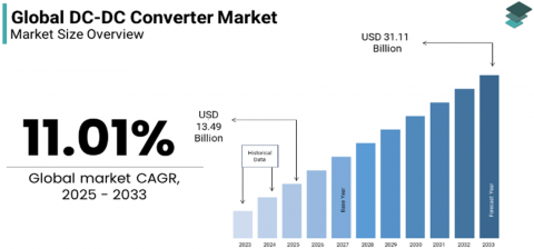
The use of DC-DC converters is rapidly increses due to the high demad for its applications. Figure 1 illustrates the market increasing demand for the DC-DC converters between 2025 to 2033 [1]. The DC-DC converter is one of the key parts of a power supply. These converters are in charge of changing the voltage levels in a system, either by raising them, lowering them, or keeping them at a constant level. There are two main types of DC-DC converters (isolaed/non isolated). Both types have the same goal: to change the level of DC voltage from one level to another. However, they are different in how they are built, how they work, and how much electrical isolation there is between the input and output. Inductors, capacitors, and switches are some of the parts that connect the input and output directly in non isolated converters [2]. Non-isolated converters are commonly used in scenarios where electrical isolation between input and output isn’t a major safety concern. Since these converters don’t provide galvanic isolation, they’re often preferred in low-power applications such as smartphones, laptops, and compact renewable energy systems where space, simplicity, and cost are key factors. Their straightforward design and efficiency make them a practical choice when full isolation isn’t necessary. On the other hand, for the isolated converters adding a transformer to make sure that the input and output are not directly connected to each other. In situations where safety and protection are one of the main goals, like in medical devices, industrial machinery, or high voltage systems, this separation can be very substantial factors [3, 4]. The transformer in these converters helps handle higher power levels and also protects sensitive circuits from possible problems [5, 6]. These converters are more complicated and are used when isolation is the target point, like when dealing with high voltages, keeping electrical noise to a minimum, or meeting regulatory standards [7, 8]. Solar power has grown significantly around the world in the last few years, and it will be an integral component of reaching the net zero target by 2050. In 2023, the world reached a new high in the amount of renewable energy it made. Different renewable energy sources around the world make about 3900 Gigawatts of energy. In that same year, China built the biggest solar photovoltaic (PV) systems in the world [9]. An efficient power electronics converter is the key point to utilize the use solar energy in our grids and storage systems. These converters are essential for adapting, storing, and distributing the electricity that solar systems make in an efficient way. Power electronics converters are the most significant component of any renewable energy system. They can step up or down voltage, manage battery storage, and control power flow in smart grids [10]. To design a high efficient converter there are many considerations should be taken to the account, such as choose the switches with minimum losses and high performance to reduce switching and conduction losses of switches [11]. Design the transformer with high frequency core materials ferrite, nanocrystalline, silicon steel, iron power to reduce the core losses [12, 13]. Power density is one of the targets for power electronics converter. Elevating the switching frequency would help to raise the power density. However, operating at high frequency has losses consequences either switching losses and galvanic isolation losses [14]. The galvanic isolation component is the dominant size for power electronics converter implying the higher the operating frequency the higher power density we get. However, galvanic isolation has to be optimized to reach an acceptable design in terms of efficiency, power density etc. In study [15], they used Ferrite N-87 core materials for design high frequency transformer. Their target is for temperature management and reduce the size of transformer. However, the results did not cover the galvanic losses aspects. In study [16], a dual active bridge transformer is designed with power level 600W, using 3C95 ferrite core material at 200 kHz. In study [17], they recommended to use the foil wire for temperature management conductivity, and power density. However, utilizing the foil would affect the cost. The study focuses on the design in general. It lacks comparison for multiple core materials. Winding type is the key factor to reduce the isolation losses. In study [18], push pull converter’s transformer is designed using two cores ETD-29 and EPC-25, with Litz wire only. The study concentrates on the effect of the core materials for the losses. The results lack the winding techniques to optimize the galvanic isolation losses. In this paper, full design procedures for push-pull converter’s galvanic isolation are discussed theoretically. Ansys PExprt software is used to verified the results for multiple core materials such as Ferrite PC40, Ferrite P, powder material Kool Mµ (90 u) and iron powder (-70). Moreover, Multiple winding types such as Round, Litz and Square are utilized to optimize the results further. The main advantages of the suggested approach are listed below:
Figure 1. The increasing of DC-DC converters market 2025-2033 [1]
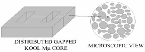
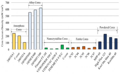
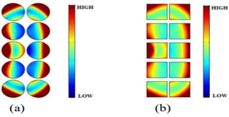
For high frequency isolation, there are different materials that can be used instead of iron to raise the power density and minimize the magnetic losses. The Ferrite has two main types. The first one is low resistivity around 1 mΩ Mn-Zn which can be used for low power applications for less than 1MHz operating frequency, high permeability and saturation flux density. The second one has high resistivity Ni-Zn which is suitable for high frequency higher than 1MHz [19]. Another type of ferromagnetic material is powder material which is mixed of powder with insulated material compressed to formation the core. they produce compressed distrusted gap to elevate the power handling for transformer. Powder cores have higher flux density, curie temperature than regular ferrite [19]. Kool Mµ is one of powder material type which it is a mixture of silicon, aluminum and iron powder. The main advantage of Kool Mµ is soft saturation and no fringing effect, the distributed gap can be controlled by increase or decrease insulating material concentration as a result the flux density can be differed (14 µ, 26 µ, 60 µ, 75 µ, 90 µ, 145 µ). These concentrations indicate of insulation amount for powder in the core. The higher concentration, the more distributed gap resulting more flux density [20]. Figure 2 demonstrates distributed gap of EE core with Kool Mµ material. In studies [21, 22] made a DC-DC converter with a power level of 33 kW and a frequency of 20 kHz. The transformer design at the converter was based on the lowest core losses, which is why multiple core materials were used. Figure 3. shows how different types of magnetic materials compare based on core losses. Amorphous is another magnetic material which can be used for low frequency up to 10 kHz, high flux density up to 1.6 T, 350℃ curie temperature. Silicon steel core material alloy of iron has high flux density for low frequency applications [23]. However, the Kool Mµ has better advantages than silicon steel such as soft saturation, lower core losses and lower cost. In this paper iron powder and ferrite material are used because they have high range of frequency, and suitable flux density. In study [24], the results explained that for high frequency the AC resistance (Rac) of winding is incresed by increasing the switching frequency. Therefore, winding losses is incresed due to skin and proximity effets. The study discussed three types of wires round, square and foil. It focus on current density at round and square wires with frequency rang 20 kHz-20 MHz where the frequency increased the leakage inductance is decreased and Rac increased leading to higher losses, for the same magnetizing inductance and cross-sectional area of square and round wire the leakage inductance for square wire increased 1.2 to 2 times compared with round wire as a result the losses are decreased as shown in Figure 4.
Figure 2. The Kool Mµ material in EE core [20]
Figure 3. Ferromagnetic material performances [22]
Figure 4. Current density (J) of wires at 20MHz (a) round wire AWG18 (b) square wire with same cross sectional area of round wire [24]
3.1 Theoretical calculations for the proposed design
To design high frequency transformer, the well known area product method (AP) can be utilized using the following steps [25].
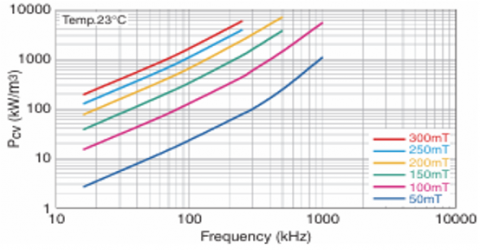
Step 1: Determine input voltage (Vs), output voltage (Vout), suitable operation flux density with the selected core material, ambient temperature, duty cycle(D), switching frequency(fs) and output power. Figure 5 shows the relation between frquency vs core losses with multipule flux density range for PC40 core material.
Figure 5. Relationship between core loss and frequencies with different flux density values of PC40 core materail [25]
Step 2: Identify the optimum core’s diemensions based on power level, flux density, and switching frequency as given by Eq. (1).
$A_p\left(c m^4\right)=\left(\frac{P * 10^4}{K_f * B_o * K_u * K_j * f_s}\right)^x$ (1)
X is constant based on core type, 1.14 for powder and laminations core type.
Kf is form factor 4.44 for sinusoidal wave, 4 for square wave.
Ku window utilization factor.
Kj constant, at 25C equal 403 for powder and 366 for laminations. Table 1. demonstrates kj for different temperatures and X [25].
Bo, the operating flux density, which is generally set to 65% or less of the Bsat for the material to avoid saturation.
Table 1. Core with Kj constant based on core shape [25]
|
Core |
Kj (25℃) |
Kj (50℃) |
X |
|
Pot Core |
433 |
632 |
1.2 |
|
Powder Core |
403 |
590 |
1.14 |
|
Laminations |
366 |
534 |
1.14 |
|
C Core |
323 |
468 |
1.16 |
|
Single Core |
395 |
569 |
1.16 |
|
Tape Core |
250 |
365 |
1.15 |
Step 3: Calculate number of primary and secondary turns as given by Eqs. (2)-(4).
$t_{o n}=\frac{1}{2 * f_s}$ (2)
$N_P=\frac{V 1 * \text { ton }}{\Delta B * A_C\left({mm}^2\right)}$ (3)
∆B the variation of flux density.
Ac cross sectional area of core.
$\frac{V_1}{V_2}=\frac{N p}{N_s}$ (4)
Step 4: Select the wire size.
Skin depth (δ) the space occupied by the current in the wire
$\delta=\frac{6.62}{\sqrt{f s}}$ (5)
Wire diameter=A=2* δ (6)
Area of wire
$A w=\frac{\pi A^2}{4}$ (7)
After this point, the AWG table can be used to select the proper winding stander size.
Step 5: Calculate the core and winding losses using Eqs. (8)-(16).
Peak value of output current
$I_{ {peak}( {out })}=\frac{V_{ {out }}}{R}$ (8)
$I_{1( { rms })}=I_{ {peak }( { out })} * 0.707$ (9)
$I_{2(r m s)}=I_{2(r m s)} * 2$ (10)
Primary Resistance
$R p=M L T * N_P *\left(\frac{\mu \Omega}{c m}\right) * 10^{-6}$ (11)
Secondary Resistance
$R s=M L T * N_s *\left(\frac{\mu \Omega}{{cm}}\right) * 10^{-6}$ (12)
MLT mean length of a turn.
µΩ/cm wire resistance also from the standard AWG table.
The winding losses for primary and secondary
Pcu Primary= I1(rms)2 Rp (13)
Pcu secondary= I2(rms)2 Rs (14)
The core losses can be calculated using Steinmetz equation [25].
$P_{\text {core }}=k * f_S^\alpha * B_0^\beta * V\left(m^3\right)$ (15)
K, $\propto$ and β are constants from core material data sheet
Total losses= Pcu Primary+ Pcu secondary+Pcore (16)
Step 6: Calculate core temperature
$\Delta \mathrm{T}=450\left(\frac{{ Total \,\, losses }}{ { surface \,\,area }=A t}\right)^{\wedge} 0.826$ (17)
Step 7: Efficiency calculation
$\eta=\left(\frac{\mathrm{P}_{\mathrm{out}}}{\mathrm{P}_{\mathrm{in}}}\right)=\left(\frac{\mathrm{P}_{\mathrm{in}}-{ Losses }}{\mathrm{P}_{\mathrm{in}}}\right)$ (18)
Losses involve core and winding losses
3.2 Numerical calculations for the proposed push-pull converter’s galvanic isolation
To design a push pull converter transformer using following parameters Vs = 50 V, D = 0.45, P = 675W, Bo = 0.2T, fs = 80 kHz, Core Material = PC40, R=12Ω, Turn Ratio = 1:2, Vout = 90V, ambient tempreture=25℃, Ku = 0.4.
According to Eq. (1), the area product can be found:
$\text A_\text p\left(\mathrm{cm}^4\right)=\left(\frac{675 * 10^4}{4 * 0.2 * 0.4 * 366 * 80000}\right)^{1.14}=0.68 \mathrm{cm}^4$
Based on the value of area product, core and bobbin can be identifies properly.
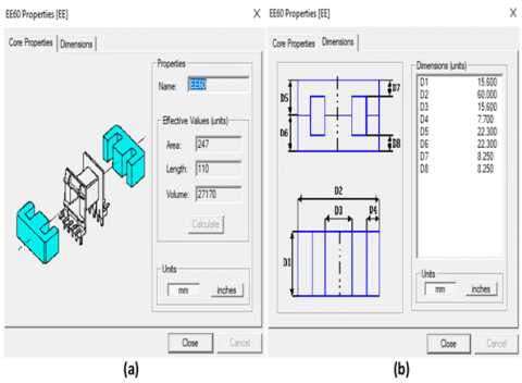
EE66 has these parameters manufacture data sheet At = 127.8 cm2, MLT = 11.3 cm, Ac = 2.47cm2.
Based on Eqs. (2)-(4), the number of primary/secondary turns can be computed as follow:
$\mathrm{t}_{\mathrm{on}}=\frac{1}{2 * 80000}=6.25 \mu \mathrm{sec}$
$\mathrm{N}_{\mathrm{P}}=\frac{50 * 6.25}{0.4 * 2.47 * 100}=3.14 \approx 4$ turn
Ns=2*4=8 turn
Eqs. (5)-(7) can be used to select the wire as follows:
$\delta=\frac{6.62}{\sqrt{80000}}=0.023$
Then calculate the diameter of wire:
A = 2* δ= 0.046 cm
$\mathrm{Aw}=\frac{\pi * 0.046^2}{4}=0.0016 \mathrm{~cm}^2$
Comparing this value with the AWG standard table, AWG25 is selected $\frac{\mu \Omega}{c m}=1062$.
To calculate the currents of primary and secondary, Eqs (8)-(10) can be utilized.
$\mathrm{I}_{\text{peak }(\text {out})}=\frac{\mathrm{V}_{\text {out }}}{\mathrm{R}}=7.5 \mathrm{~A}$
I2(rms)=0.707 * 7.5=5.3 A
I1(rms)=2 * 5.3=10.6 A
To calculate the copper losses, Eqs. (11)-(14) can be used as follows:
Primary Resistance
$\mathrm{Rp}=11.3 * 4 * 1062 * 10^{-6}=0.048 \,\, \Omega$
Secondary Resistance
Rs $=11.3 * 8 * 1062 * 10^{-6}=0.096 \,\,\Omega$
I1(rms)=10.6A, I2(rms)=5.3A.
Pcu Primary= 10.62*0.048 =5.3 W
Pcu secondary= 5.32*0.096 =2.7 W
Total copper losses=5.3+2.7=8.1 W
In order to identify the core losses, Steinmetz Eq. (15) can be used.
K = 0.32, α = 1.61, β = 2.68, V = 27 mm3 constants from core material data sheet.
$\text P_{\text {core }}=0.32 * 80000^{1.61} * 0.2^{2.68} * 27 * 10^{-6}=9 \mathrm{~W}$
To calcuate total losses:
The total losses = core losses+ copper losses =17.1 W
For the core tempreature, Eq. (17) can be used as follows:
$\Delta \mathrm{T}=450\left(\frac{17.1}{127.8}\right)^{\wedge} 0.826=85.44^{\circ} \mathrm{C}$
To calculate efficiency, Eq. (18):
$\eta=\left(\frac{675}{675+17.1}\right) * 100=97.5 \%$
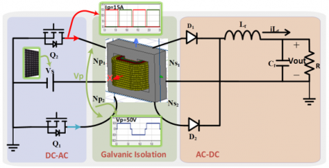
The main circuit diagram for the isolted DC-DC push-pull converter for PV applications is shown in Figure 6. For the purpose of this research, the selected frequencies of 40 kHz and 80 kHz were chosen primarily based on the material limitations and performance characteristics of the core material and components.
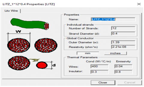
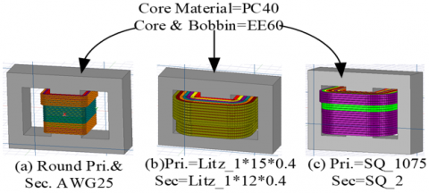
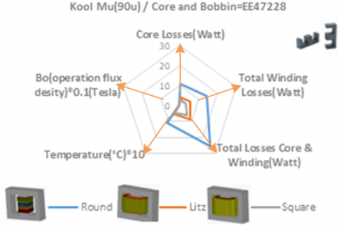
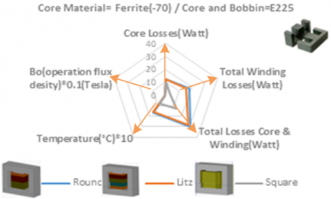
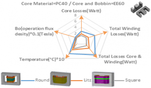
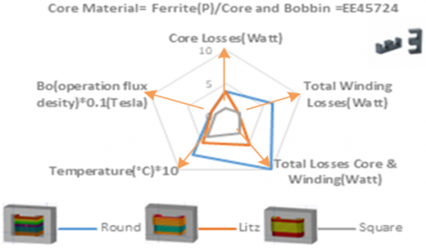
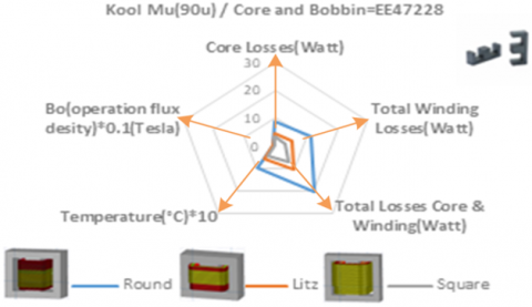
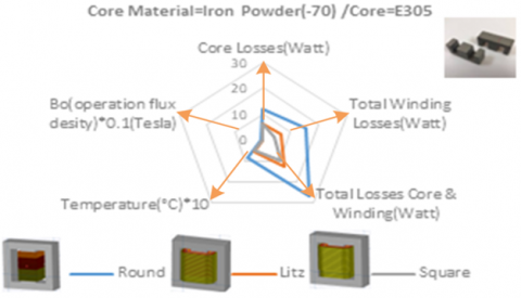
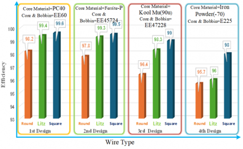
The galvanic isolation is designed utilizing four different core materials using PExprt2022R1 software. Table 2 shows the core materials Ferrite PC40, Ferrite-P, Kool Mµ (90u), and iron powder (-70). The designs involve both operating frequencies 40 kHz and 80 kHz. Tables 3 and 4 illustrate the wire types Round, Litz and Square for each design with parallel path for both operating frequency 40 kHz and 80 kHz, The first phase of the designs at 80kHz, Figure 7 shows the results Figures 8 and 9 iullstrates core size, and windings properties for EE60 core. Figure 10 shows the B-H curve of PC40 core material. Figures 11-15 show the windings proprtties such as Round, LITZ, and square wire for both primary/secondary. Figures 16 and 17 demonstarte the flux desity(B) and field intensity(H). Figure 18 depictes 3D transformers for the first design. Figure 19 combines the results of 1st design (core losses, winding losses, total losses, core temperature, operation flux density). Figure 20 shows the results of 2nd design (core material= Ferrite-P, core and bobbin= EE45724) for three type of wires Round (primary and secondary=AWG25), Litz (primary and secondary=Litz_1*15*0.4), and Square (primary=SQ_1025 and secondary=SQ_1075). Figure 21 shows the 3rd design (core material= Kool Mµ(90u), core and bobbin= EE47228) for three type of wires Round (primary and secondary=AWG25), Litz (primary=Litz_1*12*0.4 and secondary=Litz_1*15*0.4) and Square (primary=SQ_1 and secondary=SQ_2). Figure 22 illustrates the 4th design (core material= iron powder (-70), core and bobbin= E225) for three type of wires Round (primary and secondary=AWG25), Litz (primary= Litz_1*12*0.4 and secondary=Litz_1*15*0.07) , Square (primary=SQ_1 and secondary=SQ_1025). Figures 23-26 show the second phase of the designs at 40 kHz. Figure 27 shows the magnetic's efficiency of push pull converter for different wire type at 80 kHz.
Figure 6. Push-pull converter for PV system applications
Table 2. Ferromagnetic material properties [26-29]
|
Design |
Material |
Manufacturer |
Curie Temperature (℃) |
Bsat (Saturation Flux Density) (Tesla) |
Core & Bobbin (40 kHz) |
Core & Bobbin (80 kHz) |
|
1st |
Mn-Zn PC40 |
TDK |
200 |
0.39 |
EE60 |
EE60 |
|
2nd |
Ferrite-P |
Magnetics |
210 |
0.375 |
EE45724 |
EE45724 |
|
3rd |
Kool Mµ(90u) |
Magnetics |
500 |
1.09 |
EE47228 |
EE47228 |
|
4th |
Iron Powder (-70) |
Micrometals |
770 |
1 |
E305 |
E225 |
Table 3. Wire type, dimension for primary/secondary with P (Parallel Paths) at 40 kHz
|
Design |
Round Wires (Primary/Secondary) |
No of Turns {(Primary/P), (Secondary/P)} |
Litz Wires (Primary /Secondary) |
No of Turns {(Primary/P), (Secondary/)} |
Square Wires mm (Primary/Secondary) |
No of Turns {(Primary/ P), (Secondary/P)} |
|
1st |
AWG20/ AWG20 |
{(6/2), (12/1)} |
Litz_1*15*0.4/ Litz_1*12*0.4 |
{(7/2), (14/2)} |
SQ_1025/ SQ_1 |
{(8/3), (16/3)} |
|
2nd |
AWG22/ AWG22 |
{(4/2), (8/1)} |
Litz_1*15*0.4/ Litz_1*15*0.4 |
{(4/2), (8/1)} |
SQ_1025/ SQ_1 |
{(6/2), (12/2)} |
|
3rd |
AWG22/ AWG22 |
{(9/3), (18/1)} |
Litz_1*12*0.4/ Litz_1*15*0.4 |
{(12/3), (24/1)} |
SQ_1025/ SQ_105 |
{(14/3), (28/1)} |
|
4th |
AWG22/ AWG22 |
{(11/3), (22/1)} |
Litz_1*15*0.4/ Litz_1*15*0.4 |
{(15/3), (30/1)} |
SQ_105/ SQ_105 |
{(15/3), (30/1)} |
Table 4. Wire type, dimension for primary/secondary with P (Parallel Paths) at 80 kHz
|
Design |
Round Wires (Primary/Secondary) |
No of Turns {(Primary/P), (Secondary/P)} |
Litz Wires (Primary/Secondary) |
No of Turns {(Primary/P), (Secondary/P)} |
Square Wires (Primary/Secondary) |
No of Turns {(Primary/ P), (Secondary/P)} |
|
1st |
AWG25/ AWG25 |
{(4/2), (8/1)} |
Litz 1*15*0.4/ Litz_1*12*0.4 |
{(6/2), (12/2)} |
SQ_1075/ SQ_2 |
{(6/2), (12/2)} |
|
2nd |
AWG25/ AWG25 |
{(3/2), (6/1)} |
Litz 1*15*0.4/ Litz_1*15*0.4 |
{(4/2), (8/1)} |
SQ_1025/ SQ_1075 |
{(5/3), (10/3)} |
|
3rd |
AWG25/ AWG25 |
{(6/3), (12/1)} |
Litz_1*12*0.4/ Litz_1*15*0.4 |
{(10/3), (20/1)} |
SQ_1/ SQ_2 |
{(12/3), (24/1)} |
|
4th |
AWG25/ AWG25 |
{(8/3), (16/1)} |
Litz_1*12*0.4/ Litz_1*15*0.07 |
{(8/3), (16/1)} |
SQ_1/ SQ_1025 |
{(9/3), (18/1)} |
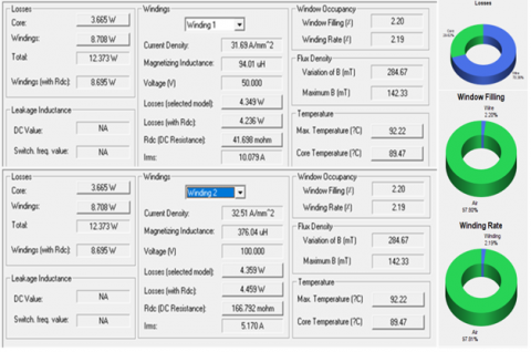
Figure 7. Magnetic performance for the first design using PExprt results for PC40 core material at 80 kHz
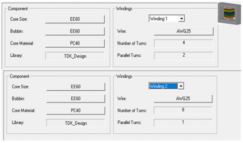
Figure 8. Core shape, material and windings size/turn
Figure 9. (a) Core properties of core EE60, (b) Core dimensions of EE60
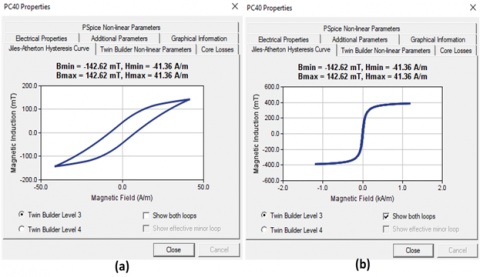
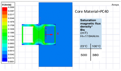
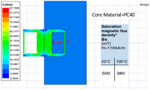
Figure 10. (a) The operation flux and field density of PC40 core material, (b) The saturation flux density and field intensity of PC40 core material
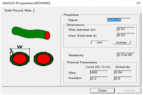
Figure 11. AWG25 round wire properties
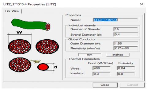
Figure 12. Litz wire properties used for 1st design Litz_1*15*0.4 for primary winding
Figure 13. Litz wire properties used for 1st design Litz_1*12*0.4 for secondary winding
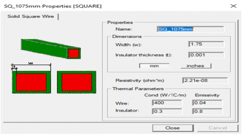
Figure 14. Square wire properties used for 1st design SQ_1075mm for primary winding
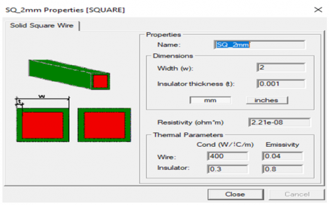
Figure 15. Square wire properties used for 1st design SQ_22mm for secondary winding
Figure 16. Flux density B of 1st design PC40 core matrial at 80 kHz with rornd wire AWG25
Figure 17. Field intensity H of 1st design PC40 core matrial at 80 kHz w ith rornd wire AWG25
Figure 18. 3D transformer structure in Ansys Maxwell for 1st design Primary and secondary (a) Round wire, (b) Litz
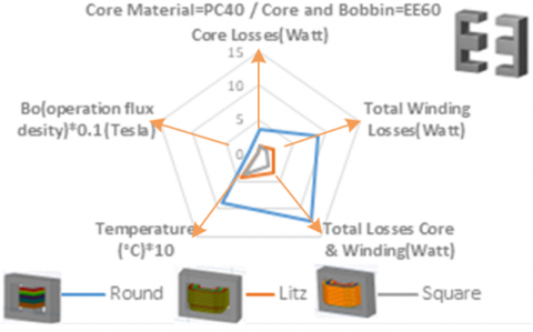
Figure 19. Operation flux density, core tempreture, core, winding and total losses of 1st design at 80 kHz for PC40
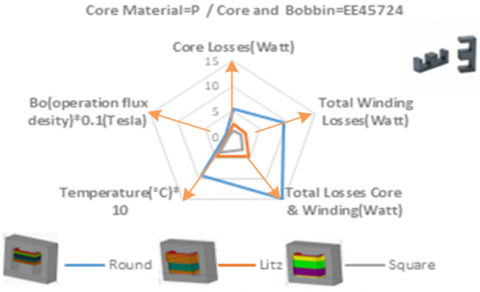
Figure 20. Operation flux density, core tempreture, core, winding and total losses of 2nd design at 80 kHz for Ferrite-P
Figure 21. Operation flux density, core tempreture, core, winding and total losses of 3rd design at 80 kHz for Kool Mµ
Figure 22. Operation flux density, core tempreture, core, winding and total losses of 4th design at 80 kHz for iron powder (-70)
Figure 23. Operation flux density, core tempreture, core, winding and total losses of 1st design at 40 kHz for PC40
Figure 24. Operation flux density, core tempreture, core, winding and total losses of 2nd design at 40 kHz for Ferrite-P
Figure 25. Operation flux density, core tempreture, core, winding and total losses of 3rd design at 40 kHz for Kool Mµ
Figure 26. Operation flux density, core tempreture, core, winding and total losses of 4th design at 40 kHz for iron powder (-70)
Figure 27. Efficiency of 1st, 2nd, 3rd and 4th designs for round, Litz and square wires (wire detailes are given in Table 4)
This article has covered the push-pull converter’s galvanic isolation designs using different types of core materials Ferrite PC40, Ferrite-P, Kool Mµ(90u), and iron powder (-70) along with multiple winding types for instance Round, Litz, and Square. For each magnetic core, three types of windings are used to find the best performance in terms of low losses, core temperature, and operation flux density. The distribution of flux density and field intensity in 2D, 3D transformer structure are obtained via ANSYS MAXWELL to achieve valid designs. PC40 has low core losses; at 40 kHz, the best case is PC40 with square wire with losses (2.302W); the round with PC40 is the worst case in the 1st design with total losses (6.49 W), while iron powder (-70) material has higher losses, the worst case with round wire (27.178 W) but the best case at the 4th design with square wire with losses (10.19). The best results are achieved by utilizing the square wire. SQ-1075mm for the primary winding and SQ-2mm for the secondary winding resulting to best magnetic performance, with total losses were (2.609 W) (1.408) watts for primar/secondary losses respectively and only 1.201 watts for core losses at 80 kHz. This configuration results 99.6% magnetic efficiency. On the other hand utilizing the iron powder (-70) as the core material and round wire AWG25 for both the primary/secondary resulted in least efficient design. The core losses are 12.636 watts, winding losses are 17.97 watts resulting to 95.7% efficiency. For the curie temperature and flux density, iron powder and Kool Mµ are better than Ferrite materials. The Curie temperature of iron powder and Kool Mµ can reach 700℃, while the Curie temperature of Ferrite materials can only reach 250℃. it is worth to mention the practical challenges associated with their use. From a manufacturing perspective, square wires can be more difficult and costly to produce compared to round wires, as their fabrication requires more precise and specialized equipment. Additionally, the cost of square wires is generally higher due to the additional processing steps involved in their production.
The authors wish to extend their sincere gratitude to the University of Mosul, Iraq, for its invaluable support and assistance with this work.
[1] Europe Subsea Umbilicals, Risers, and Flowlines Market. https://www.marketdataforecast.com/market-reports/europe-subsea-umbilicals-risers-and-flowlines-market.
[2] Janabi, A., Baranwal, R., Zhang, Z., Patil, D.R., Zhu, G., et al. (2024). U.S. Patent Application No. 18/269,415.
[3] Ertugrul, N., Abbott, D. (2020). DC is the Future [Point of View]. Proceedings of the IEEE, 108(5): 615-624. https://doi.org/10.1109/JPROC.2020.2982707
[4] Hammo, A.N., Sabry, S.S., Saied, B.M. (2024). Design and evaluation of galvanic isolation for full bridge DC to DC converter. Journal Européen des Systèmes Automatisés, 57(3): 833-840. https://doi.org/10.18280/jesa.570322
[5] Morey T. (2009). Switching Power Supply Design. Third Edition. https://d1.amobbs.com/bbs_upload782111/files_41/ourdev_652687FB25XY.pdf.
[6] Sabry, S., Pool-Mazun, E.I., Enjeti, P. (2019). A medium voltage DC collection grid for large scale PV power plant with SCR converter and integrated solid-state transformer (SST). In 2019 IEEE Energy Conversion Congress and Exposition (ECCE), Baltimore, MD, USA, pp. 5824-5831. https://doi.org/10.1109/ECCE.2019.8913251
[7] Danial, W.H. (2010). Commonly used Power and Converter Equations. Power Electronics. https://cmosedu.com/jbaker/courses/ee442_ecg642/Power_Electronics_Daniel_W_Hart.pdf.
[8] Sabry, S., Enjeti, P. (2020). High frequency integrated solid state transformer (SST) for utility interface of solar pv/battery energy storage systems. In 2020 IEEE Applied Power Electronics Conference and Exposition (APEC), Orleans, LA, USA, pp. 546-553. https://doi.org/10.1109/APEC39645.2020.9124199
[9] Al-Greer, M., Chowdhury, R.I., Sajeevan, A.C., Sabry, S.S., Suhail, A.M., Abdulwahid, O. (2024). Solar energy education: Curriculum framework development. In 2024 IEEE International Symposium on Systems Engineering (ISSE), Perugia, Italy, pp. 1-6. https://doi.org/10.1109/ISSE63315.2024.10741109
[10] Nayanasiri, D.R., Foo, G.H.B., Vilathgamuwa, D.M., Maskell, D.L. (2014). A switching control strategy for single-and dual-inductor current-fed push–pull converters. IEEE Transactions on Power Electronics, 30(7): 3761-3771. https://doi.org/10.1109/TPEL.2014.2348800
[11] Millan, J., Godignon, P., Perpiñà, X., Pérez-Tomás, A., Rebollo, J. (2013). A survey of wide bandgap power semiconductor devices. IEEE Transactions on Power Electronics, 29(5): 2155-2163. https://doi.org/10.1109/TPEL.2013.2268900
[12] Ishimine, T., Watanabe, A., Ueno, T., Maeda, T., Tokuoka, T. (2011). Development of low-iron-loss powder magnetic core material for high-frequency applications. SEI Technical Review, 72: 117-123.
[13] Sabry, S.S., Alsammak, A.N.B. (2024). Power density enhancement of three-phase rectifier using higher frequency solid state transformer. Mathematical Modelling of Engineering Problems, 11(5): 1286-1292. https://doi.org/10.18280/mmep.110518
[14] Ortiz, G., Biela, J., Kolar, J.W. (2010). Optimized design of medium frequency transformers with high isolation requirements. In IECON 2010-36th Annual Conference on IEEE Industrial Electronics Society, Glendale, AZ, USA, pp. 631-638. https://doi.org/10.1109/IECON.2010.5675240
[15] Bin, C. (2019). Design optimisation of an inductor-integrated MF transformer for a high-power isolated dual-active-bridge DC-DC converter. IET Power Electronics, 12(11): 2912-2922. https://doi.org/10.1049/iet-pel.2019.0069
[16] Delette, G., Soupremanien, U., Loudot, S. (2022). Thermal management design of transformers for dual active bridge power converters. IEEE Transactions on Power Electronics, 37(7): 8301-8309. https://doi.org/10.1109/TPEL.2022.3152692
[17] Wouters, H., Shen, X., Pervaiz, H., Martinez, W. (2023). Optimisation of magnetic loss trade-offs in high-frequency litz wire transformers. In 2023 25th European Conference on Power Electronics and Applications (EPE'23 ECCE Europe), Aalborg, Denmark, pp. 1-11. https://doi.org/10.23919/EPE23ECCEEurope58414.2023.10264333
[18] Hassan, R.F., Hameed, K.R. (2020). Design of high frequency transformers in different shape of core using matlab program. Indonesian Journal of Electrical Engineering and Computer Science (IJEECS), 20(3): 1159-1172. https://doi.org/10.11591/ijeecs.v20.i3.pp1159-1172
[19] Hurley, W.G., Wölfle, W.H. (2013). Transformers and inductors for power electronics: Theory, design and applications. John Wiley & Sons. https://doi.org/10.1002/9781118544648
[20] Horgan, M.W. (2000). Leakage flux considerations on Kool Mµ E cores. Magnetics Technical Report.
[21] Somkun, S., Sato, T., Chunkag, V., Pannawan, A., Nunocha, P., Suriwong, T. (2021). Performance comparison of ferrite and nanocrystalline cores for medium-frequency transformer of dual active bridge DC-DC converter. Energies, 14(9): 2407. https://doi.org/10.3390/en14092407
[22] Beraki, M., Trovão, J.P., Perdigão, M. (2020). Comprehensive comparison and selection of magnetic materials for powertrain DC–DC converters. IET Electrical Systems in Transportation, 10(2): 125-134. https://doi.org/10.1049/iet-est.2019.0113
[23] Rashid, M.H. (Ed.). (2017). Power Electronics Handbook. Butterworth-Heinemann.
[24] Nia, M.S.S., Saadatmand, S., Altimania, M., Shamsi, P., Ferdowsi, M. (2019). Analysis of skin effect in high frequency isolation transformers. In 2019 North American Power Symposium (NAPS), Wichita, KS, USA, pp. 1-6. https://doi.org/10.1109/NAPS46351.2019.9000395
[25] Ummah, M.S. (2018). Magnetic core selection for transformers and inductors: A user's guide to practice and specifications. CRC Press. https://api.pageplace.de/preview/DT0400.9781482273625_A35585506/preview-9781482273625_A35585506.pdf.
[26] Ferrite, M. Material characteristics. Ferrite for Switching Power Supplies. https://product.tdk.com/info/en/catalog/datasheets/ferrite_mn-zn_material_characteristics_en.pdf.
[27] P Material Magnetics. https://www.mag-inc.com/Products/Ferrite-Cores/P-Material.
[28] Bulletin, T. (2013). Large Kool Mµ ® Core Shapes. https://www.mag-inc.com/Media/Magnetics/File-Library/Product%20Literature/Powder%20Core%20Literature/Large-Kool-Mu-Shapes.pdf.
[29] Micrometals, Iron Powder (-70). https://powermagneticsstore.co.uk/shop/micrometals-iron-powder-cores.html.