Noor Hatem![]() | Mohammed Mustafa Abedlhafd*
| Mohammed Mustafa Abedlhafd*![]() | Azzam Dawood Hassan
| Azzam Dawood Hassan![]() | Nuha Hadi Jasim Al Hassan
| Nuha Hadi Jasim Al Hassan![]() | Yusri Yusof
| Yusri Yusof![]() | Yazid Saif
| Yazid Saif![]() | Iliyas Maznah
| Iliyas Maznah![]()
© 2025 The authors. This article is published by IIETA and is licensed under the CC BY 4.0 license (http://creativecommons.org/licenses/by/4.0/).
OPEN ACCESS
Computer Numerical Control (CNC) is an important production factor in these modern times, since this method has brought precision, efficiency, and flexibility to such industries as electronics, aerospace, and automobile manufacturing. However, while this system merits consideration, it sometimes happens that traditional systems have limitations, mostly because of their proprietary software, which puts some constraints on the ability to customize and optimize. This work presents a software development that uses a genetic algorithm to extract and subsequently optimize drilling G-Code, where the software is developed for open CNC controller architectures. The method involves developing the necessary G-Code, building a distance matrix, and a genetic algorithm to be used in which the routes that provide maximum productivity will be obtained. From them, a rise in efficiency for the toolpaths up to 18%, with considerable shortening in travel lengths as well as a reduction of the machining time of the material, can be established. The evidence from these findings is that the ability of genetic algorithms to enhance the CNC machining process for cost savings and industrial efficiency is very clear. It is indicated that industries in search of intelligent and flexible CNC machinery with conformance to the requirements of Industry 4.0 can be guaranteed scalability by this approach.
drilling, open CNC controller, process optimization, genetic algorithm, tool path
Computer Numerical Control is a conceptual technology, important in present modes of production for control use or operation through information from program control. These have ranged from different industries in many fields in the recent decades, from aerospace, automotive manufacturing to electronics [1]. In such developmental processes using this means, each sector enjoys ultimate accuracy attributed to CNC systems, and each repeatedly improves their efficiency. The advantages of combining automation and NC machines through the introduction of this invention include the potential to attain low-manned error, effectiveness to give rise to higher output, and high-volume production at high quality as a whole. Beyond this, CNC systems allow for sophisticated designs and geometries that are hard to tackle or impossible by hand. Thus, CNC machining has led to the frontline of contemporary production systems and Industry 4.0, wherein its integration with IoT and smart technologies increases operating abilities further [2].
Conventional CNC systems are often constrained by proprietary software and hardware that forbid users from making any modifications or enhancements. Open CNC designs go beyond these limitations, allowing flexibility and adaptability in the platform [3]. In an open CNC system, the manufacturer can modify the control algorithms, integrate third-party software, and personalize machine characteristics to meet specific needs [4]. The above openness allows the customers' innovations, which seek to optimize the cutting pathways and shorten cycle times to improve the surface finishes. An additional advantage of open CNC is that there is lesser dependence on one or few suppliers, hence less proprietary upgrades of software and hence reduced license fees costs. Industries using open CNC may respond promptly to changed production requirements and technical improvements [5].
This is quite an advantage for companies wishing to improve some aspects of manufacturing. With open-source CNC-systems, it becomes possible to upgrade the functionality of machines provided by engineers and developers in order to have the ability to apply changes in real-time, and to use some algorithms in improving cutting conditions [6]. The functions tailored are custom user interfaces, control parameters as well as industrial system compatibility, allowing easy communication and data transfer. Adaptive control algorithms can automatically readjust the cutting speed and tool path in real time based on sensor signals to minimize material waste and tool wear [7]. Such flexibility enables manufacturers to address specific challenges while continuing to improve machining accuracy, productivity, and consistency [8].
In CNC machining, the goal of optimization is to increase operational efficiency with minimum resource consumption. Tool path optimization, adaptive feed rate regulation, and predictive maintenance algorithms are some of the essential methods for cost and time reduction [9, 10]. For instance, optimization of tool routes reduces idle times and material waste [11], hence directly affecting production costs. These are now supplemented in modern CNC systems through the employment of machine learning and artificial intelligence so as to predict the wear in the tool for optimum changes of the parameters of cut in real-time. The saving thus brought about is in cost and a quicker manufacturing cycle time with minimum or no consumption of productive time in an economical and optimized method related to the tool usage for any particular manufacturer. Cloud-connected systems further allow for remote monitoring and, thereby, optimization of operations with scalability [10].
Genetic algorithms (GA) are stochastic search and optimization techniques inspired by natural evolution. In the context of CNC drilling optimization, the problem can be modeled as a variant of the Traveling Salesman Problem (TSP), where the tool must visit a sequence of drilling points with minimal non-cutting movement. Recent works [12, 13] have validated the use of GAs in similar path-planning contexts. This work describes the development of a software system for the extraction and optimization of drilling G-Code by means of a Genetic Algorithm, to be used on an open Computer Numerical Control controller. Compared to traditional linear execution, GA-based reordering adapts tool paths based on spatial efficiency, offering real-time benefits for open CNC systems. Our review also considers recent algorithmic enhancements like elitism, adaptive mutation, and hybrid strategies used in drilling path optimization and additive manufacturing.
At its core, a CNC machine comprises three primary sections:
2.1 The software
For the analysis of such CAD models and the subsequent conversion into machine-readable codes, there is a requirement for appropriate CNC software [14]. G-Code will define the toolpaths, position, and movements of the cutting tools, making sure the machining operations are properly introduced. Meanwhile, M-Code controls auxiliary actions such as on/off coolant systems, spindles on/off, or tool changes. Taken together, these codes are the basis of the CNC programming language that enables accurate control and smooth coordination in complex manufacturing processes.
2.2 The Machine Control Unit (MCU)
The MCU serves as a control unit for a CNC machine with the help of instructions provided through G-Code and M-code. It regulates tool path, speed of the cutting tool, feeding of the workpiece, and peripheral operations such as coolants and changing of tools. The MCU enables seamless communication between software directives and physical elements of the machine [15].
2.3 The processing equipment
This component includes the machine tools responsible for various machining operations such as turning (Lathe CNC machine), milling (Milling CNC machine), drilling (Drilling CNC machine), grinding (Grinding CNC machine) and cutting (Plasma and Laser CNC machines). Each type of CNC machine is specialized for its respective operations, allowing for high precision and repeatability [16, 17].
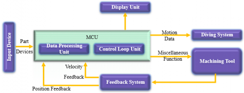
A CNC machine integrates several hardware components, each playing a crucial role in ensuring efficient operation, precision, and feedback control. The key components are described below. Figure 1 provides a visual representation of the hardware components of a CNC machine system and their interconnections, offering a clearer understanding of their roles and interactions within the CNC system.
3.1 Input devices
Input devices are responsible for feeding part programs into the CNC control unit, especially when not integrated with CAD/CAM software. Common input methods include USB flash drives, Ethernet communication via LAN cables, conversational programming, and serial communication (e.g., RS-232-C serial port) [18, 19]. These devices act as the entry point for motion and auxiliary function data, as illustrated in Figure 1.
Figure 1. Computer numerical control (CNC) hardware components
3.2 Machine Control Unit (MCU)
This comprises the MCU, the heart of any CNC system, which drives control action efficiently and with precision. It includes two major sub-units: control loop unit and data processing unit. These sub-units support MCU to read and decode G-Code and M-code instructions, which describe the basic details of machining operations [19]. The MCU performs geometric interpolations like linear, helical, and circular motions in order to generate the real command of axis motion; then sends the same to the drive system for the control of machine motions. Moreover, it will also process the position and velocity feedback information in real time, ensuring accuracy and stability [20]. It also supports peripheral operations, including tool changes and coolant on/off, during processing. MCU works like the central processor in the CNC system; it carries out all the operations regarding control smoothly without any mistake, as shown in Figure 1.
3.3 Machine tool
The machine tool has two major components: the spindle, which provides and regulates the rotation motion along the Z-axis, and the slide table, which provides and regulates horizontal and vertical movements along the X and Y axes. These components work together to ensure precise positioning and motion of the workpiece and the cutting tool [16].
3.4 Feedback or measuring system
The feedback system includes sensors such as position and velocity transducers that continuously monitor the speed and position of the cutting tool. Signals obtained from these sensors are fed back to the MCU, where their values are compared in real time with a reference signal [21]. Such a comparison allows for error correction, minimization of position and speed difference, and thus the assurance of accurate machine performance.
3.5 Driving system
In summary, the propulsion system provides support through drive motors, a ball lead screw, and an amplifier circuit. Working as a whole, this helps the MCU translate the commands sent related to the axis into actually accurate physical movements [18]. The drive motors drive the ball lead screws forward for the purpose of precise movement, by which the slide table and spindle are placed to assure desired locations of machining with increased high precision.
3.6 Display unit
The display unit, with GUI-based application software, provides operators with a comprehensive interface for operating and managing the CNC system. It displays immediate information about the condition of the system, control commands, and information about the program. Such a user-friendly interface enables the operator to monitor processes, change settings, and diagnose problems in an easy way, as shown in Figure 1.
The CNC machine system functions as a cohesive network of all these components. The MCU serves as the central processing unit, interfacing with input devices that supply CNC programs and display units that present real-time operating data. The data processing unit and control loop unit of the MCU manage program execution, geometric interpolations, and control signal processing. These signals are subsequently sent to the driving system, where drive motors and amplifier circuits transform them into the actual motions of the cutting tool. The feedback systems concurrently monitor velocity and position, transmitting real-time information to the MCU for precise control and fault rectification [22].
This closed-loop control system ensures seamless coordination among all components: the input device initiates the motion workflow and auxiliary function data, the feedback system completes the loop by transmitting essential information to the MCU, the display unit acts as a crucial interface for monitoring system performance, and the machining tool performs cutting, milling, or drilling tasks with precision [23].
The integration of these technologies creates a fully synchronized CNC machine capable of executing complicated machining operations with great accuracy, consistency, and efficiency, rendering it essential for contemporary manufacturing and industrial applications.
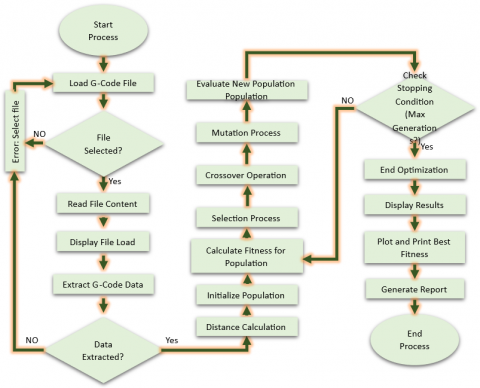
The system describes the whole processing chain of a G-Code file in the application. Starting from the selection and loading of the G-Code file, it goes on to extract important commands with the help of regular expressions. Further, the process describes how the extracted data are updated and fine-tuned based on user input. It will then calculate distances among them, building a distance matrix that will give the basics for the optimization of CNC routes through a genetic algorithm. Everything is wrapped up in the sophisticated presentation of data in 3D plots and the generation of extensive reports in most of the known formats. All this is cut to size at each step to assure efficient control, analysis, and improvement in G-Code, while embedding users with firm resources and tools to boost their effectiveness in operating computer numerical control. Figure 2 depicts the flowchart for processing the input file in a step-by-step manner.
The flowchart begins by the user's initiation through file selection to be analyzed in G-Code. A G-Code file, usually a set of instructions for CNC machining, is selected through a file dialog that allows the user to navigate their computer and select the appropriate file. If no file is selected, it throws an error back to the user for file selection. This first kind of validation ensures that at least a valid file is provided once the action is to be taken upon. If the file is well-selected, it reads the sequential data from it line by line. The raw G-Code information is displayed out in the GUI; all this shows the user the data that have just been imported and confirms the correct reading. This prompt response allows the user to confirm that the correct file has been chosen and that its contents are what is expected, prior to beginning the extraction process.
After the presentation of the imported data, the system proceeds with the extraction of some of the G-Code commands from the file. The extraction process utilizes regex patterns for key instructions such as X, Y, Z for coordinate values; S, spindle speed; F, feed rate; M, miscellaneous functions; R, radius; and T, tool adjustments. Indeed, this is a systematic compilation of the G-Code commands, with each command formatted as a dictionary for every line. The collected data are then depicted in the GUI, which allows the user to confirm that the commands were correctly processed and arranged.
It then checks for the success of the extraction. If the information taken out is incomplete or incorrect, the process goes back to moving, which requires the user to go back to the very start-step of file selection. This ensures that only correctly structured and extracted data flow further in the workflow, thus reducing the risk of issues in subsequent processing steps.
Figure 2. Flowchart of implemented genetic algorithm
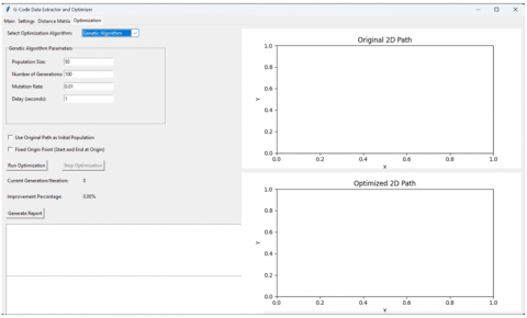
Figure 3. Graphical user interface of the GA optimization software
It calculates the distance matrix by using the X and Y coordinates of the data extracted for comparison of efficiency between different approaches. This matrix calculates pairwise distances between all points, which forms the backbone of understanding the spatial relationships within the CNC program. This distance matrix will form the basis of comparison for the efficiency of each approach and helps the algorithm to determine the more efficient ones. Thus, upon calculation of the distance matrix, the system makes preparations by initializing a population for GA-based optimization. Several candidate optimal paths include distinct rearrangement or sequences of G-Code statements each flowing with one another. In relation, and upon the initialization, improvement to this population will build a base for identifying and enabling this best route through orders via successive generations.
The fitness of each subject in the population is calculated using the distance matrix computed. At this stage, this normally adopts minimizing on every single route from the overall trip distance traveled by each of the CNC machines. Fitness scores will, therefore, inform selections in which the most fit are those that get to progress and move into the next successive stages of the genetic algorithm in action. The selection phase of the system chooses the most effective solutions from the existing population. The selected individuals are then taken to the crossover process, where pairs of solutions are used in generating offspring for the next generation. Crossover involves combining series of commands from two parents, which results in new solutions that can include desirable features from either parent.
The mutation phase ensues, implementing minor random alterations to the progeny. This stage preserves genetic variety among the population and prevents the algorithm from becoming ensnared in local optima. By marginally modifying the trajectories, the mutation process enables the algorithm to investigate a broader spectrum of potential solutions, hence enhancing the probability of identifying a more optimum path. The newly created population is subsequently assessed for fitness following mutation. The system persistently cycles through the phases of selection, crossover, mutation, and assessment until a predetermined stopping criterion is satisfied. The termination criterion may rely on attaining a maximum number of generations or earning an acceptable fitness score. Should the condition remain unfulfilled, the mechanism reverts and reiterates the optimization cycle. The optimization procedure concludes when the halting condition is met. The optimal solution, which signifies the most effective arrangement of G-Code commands, is determined. The optimized path is shown in the GUI, offering users a summary of the outcomes and the enhancements in efficiency attained.
The software interface called "G-Code Data Extractor and Optimizer" is shown in Figure 3. Users can choose the optimization algorithm, set the parameters for the genetic algorithm, such as the size of the population, the number of generations, and the mutation rate, and then start the optimization process. It shows both the original and optimized 2D toolpaths in real time using side-by-side plots. Other features include tracking of generations, showing the percentage of improvements, and automatic report generation. These features give users a clear and interactive optimization workflow.
The system provides a visualization option for a more thorough investigation. The refined data can be shown in two dimensions, illustrating the sequence of commands and the resultant trajectory within a geographic framework. Users can engage with the plot, rotating and zooming to enhance their comprehension of the arrangement and progression of the optimal commands. This image facilitates the verification of optimization and assists users in interpreting the spatial relationships among various places.
The user can produce a comprehensive report. The report encompasses all phases of the process: the first extracted data, the optimization advancements, and the ultimate optimized outcomes. The report may be saved in several formats, including text files, Word documents, or Excel spreadsheets, offering a thorough record of the whole process for future reference or study. The procedure culminates with the user either resetting the system for a new task or terminating the program. The user possesses a comprehensive grasp of G-Code data management, encompassing extraction, optimization, and visualization, hence enabling informed decision-making for CNC machining jobs. The flowchart clearly demonstrates a systematic approach to processing and optimizing G-Code data, guaranteeing efficiency and clarity throughout the workflow.
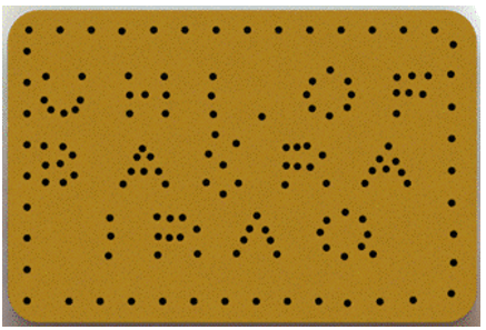
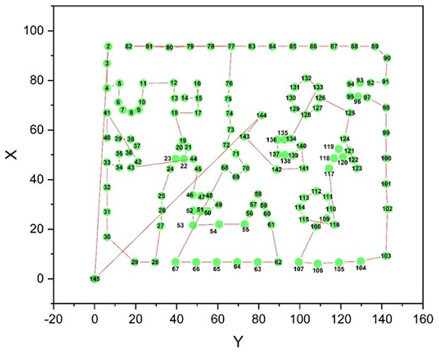
The drilling points selected are based on the letters UNI.OF BASRA IRAQ which refer to UNIversity OF BASRA IRAQ border by points (Figure 4). Solid Work with Solid Cam software was used to draw the CAD design and machining features, respectively.
G-Code is generated for CAD drawing to understand drilling extracted and optimization using the developed system. The ISO 6983 code that is generated concerning the designed object is illustrated in Appendix A. The system.exe is launched, followed by the selection of G-Code with drilling data for the interface model environment, and the resultant code is uploaded to the system using the “Open G-Code File” button. Concerning the drilling procedure, the system extracts 145 points as the drilling locations. The route length of the ISO code produced by the Solid Cam software's "shortest distance technology" function is 1460.39 mm. Figure 5 illustrates the series of retrieved drilling points (minimum distance) from the solid cam program. To elucidate the progression of the produced system code, a segment has been chosen from our example. The initial 10 places are selected, with the origin point serving as both the commencement and conclusion of the trip.
Figure 4. CAD design of drilling point
Figure 5. Extracted drilling points from G- code
The flowchart in Figure 2 provides outlines of the process for optimizing a system using a genetic algorithm. It begins with loading and extracting G-Code data, then initializing a population. Subsequently, the fitness of the population is calculated, followed by selection, crossover, and mutation processes to create a new population. This cycle repeats, evaluating the new population each time. The process continues until a stopping condition, such as reaching a maximum number of generations, is met. The genetic algorithm uses a population size of 50 to maintain diversity, a 1% mutation rate to avoid local optima, and runs for 10000 generations to balance optimization and runtime. These parameters follow established evolutionary computation principles [24] and achieved an 18% reduction in toolpath distances. The main steps of the genetic algorithm are:
Step 1: Initialization
The objective here is to create an initial population of possible solutions (tours). Each tour is represented as a permutation of the cities. Since the salesman must start and end at point 0, we fix the start and end points, while permuting the intermediate cities. For illustration, the system generates a population of four paths:
- Path 1: [0, 1, 2, 3, 4, 5, 6, 7, 8, 9, 10, 0]
- Path 2: [0, 3, 5, 2, 1, 4, 7, 6, 9, 8, 10, 0]
- Path 3: [0, 2, 4, 1, 3, 5, 9, 8, 7, 6, 10, 0]
- Path 4: [0, 5, 3, 2, 4, 1, 6, 7, 10, 9, 8, 0]
This initial population is generated randomly.
Step 2: Evaluation
In this step, the system calculates the total distance of each tour using the Euclidean distance formula between consecutive cities in the tour. For example:
- For Path 1: The total distance is approximately 230.004, calculated as the sum of distances between the points:
93.98 + 6.91 + 10.00 + 6.30 + 7.63 + 3.78 + 4.33 + 3.69 + 3.41 + 7.66 + 82.31 ≈ 230.004
The total distances for the paths are:
- Path 1: 230.004
- Path 2: 248.33
- Path 3: 257.857
- Path 4: 242.557
Step 3: Fitness calculation
The goal of this step is to assign a fitness score to each path based on their total distance: shorter distances correspond to higher fitness. The fitness is calculated as the inverse of the total distance. For instance, for Path 1 with a total distance of 230.004, the fitness is approximately 0.0043. The fitness scores for all paths are as follows:
- Path 1: 0.0043
- Path 2: 0.004
- Path 3: 0.0038
- Path 4: 0.0041
Step 4: Selection
In this step, paths are selected for reproduction based on their fitness, with higher fitness paths having a greater chance of selection. The system uses the Roulette Wheel Selection method, where the probability of selection is proportional to fitness.
- Total Fitness = 0.0043 + 0.004 + 0.0038 + 0.0041 = 0.01637
The selection probabilities for each path are:
- Path 1: 0.2655
- Path 2: 0.2459
- Path 3: 0.2368
- Path 4: 0.2518
Based on these probabilities, paths 1 and 4 are selected for reproduction.
Step 5: Crossover
The objective of this step is to combine parts of two parent tours to produce offspring, inheriting characteristics from both parents. The system uses the Order Crossover (OX) method, which is common for the Traveling Salesman Problem (TSP) as it preserves the relative order of cities.
For example, suppose the system select Parents 2 and 3:
- Parent 2: [0, 3, 5, 2, 1, 4, 7, 6, 9, 8, 10, 0]
- Parent 3: [0, 2, 4, 1, 3, 5, 9, 8, 7, 6, 10, 0]
The system randomly chooses crossover points, say positions 3 to 7 (inclusive), and extracts the subtour from Parent 2: [2, 1, 4, 7, 6]. The system then fills the remaining cities from Parent 3, excluding the cities already in the subtour, to form Child 1: [0, 2, 1, 4, 7, 6, 3, 5, 9, 8, 10, 0]. The system generates a second child similarly.
- Child 1: [0, 2, 1, 4, 7, 6, 3, 5, 9, 8, 10, 0]
- Child 2: [0, 3, 5, 2, 1, 4, 7, 6, 9, 8, 10, 0] (which may resemble Parent 2).
After crossover, the new generation replaces the old one (either fully or partially). The system repeats the evaluation, fitness calculation, selection, and crossover steps for a predefined number of generations or until convergence.
For example, in a new iteration:
- The new population consists of Child 1, Child 2, and Paths 1 and 4.
- The total distances and fitness scores are recalculated for the new population, and selection and crossover steps are performed again to generate the next generation.
This iterative process continues until it reaches the specified number of generations. The genetic algorithm effectively reduced the total path distance, improving the efficiency of the toolpath for the CNC machine. This optimization is achieved by iteratively refining possible solutions and favoring paths that reduce overall travel.
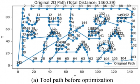
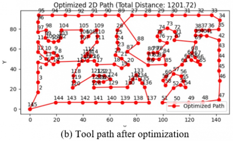
Figure 6 provides a comparison between the original and optimized toolpaths generated from a sequence of G-Code commands. In CNC machining, the sequence in which the tool visits different coordinates significantly affects the efficiency of the process. The flow of the paths in these plots, shown before and after optimization, demonstrates how rearranging the command order can reduce the total travel distance, thereby improving operational efficiency.
In Figure 6 (a), a 2D plane is used to plot G-Code commands represented by blue markers and connected with lines. The path is taken in the order found in the original G-Code file without any optimizations applied. The same visualization is explained: Each point corresponds to a (X, Y) coordinate that was extracted from the data, and the label corresponds to a sequential number. In a non-optimized state, the total distance covered by the CNC tool is 1460.39 mm. The route appears confused and ineffective, it jumps from different line segments, even switching directions on certain lines. This means that the tool is path running unnecessarily long and can result in an increased move time as well as possible wear on the machine.
Figure 6. Tool path from python code
Conversely, Figure 6 (b) shows the results of using a genetic algorithm to achieve a more efficient ordering of G-Code commands. The red marks and lines represent the adjusted trajectory, and the order of the places now varies significantly. Thus, the optimization process tends to reduce the distance traveled by permuting the order of these coordinates, while respecting essential operations from the G-Code. This gives the resulting path a smooth flow with no sharp angles and no crossovers, meaning a straighter route passed through all locations. The distance of the optimized path is 1201.72 mm, showing a significant increase compared to the original one, which includes approximately 18% improvements in travel efficiency.
Having the two trajectories was intentional because it shows the impact the optimization makes. The reduced linear path reduces the overall distance traveled and improves the effective operation of the CNC machine. Fewer unnecessary movements allow the updated sequence for lower processing time, lower tool wear, and improved overall performance. This optimization is crucial in industrial implementations, as even minor reductions in travel distance can translate to significant time and monetary savings.
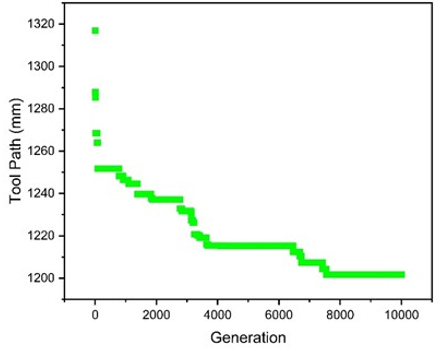
The implementation of a genetic algorithm adjunction on the drilling tool route optimization is demonstrated in Figure 7. The tool path length starts at approximately 1320 mm and decreases with newer generations, reaching 1200 mm by the 6000th generation. This gradual decline with a few jumps (i.e. plateau) demonstrates the capability of the genetic algorithm to iteratively make improvements. Exploration is dominant in initial generations, which leads to quick progress, while exploitation dominates in later generations, which refines the best solutions. Improving the tool path offers significant benefits such as a reduction in machine running time, power consumption, and tool wear, ultimately leading to cost savings. Fewer extraneous movements translate into enhanced productivity and efficiency; as such, the refined G-Code translates directly into a more productive and efficient workflow. As a result, the iterative nature of the GA is especially suited to the control of complex geometries or multiple apertures.
Figure 7. Optimization of tool path length across generations in the implemented genetic algorithm
Adjusting GA parameters, such as mutation rates and population size, can be utilized to balance exploration and exploitation, potentially leading to improved outcomes. Convex gaps there might lead to faster convergence with hybrid methods such as interaction of genetic algorithms with local search techniques. Incorporating finite world constraints and computing cost would yield realistic and feasible results. The proposed method is an effective approach for enhancing machining operations using genetic algorithms.
In order to evaluate the effectiveness of the proposed genetic algorithm (GA) in comparison to our previously developed Ant Colony Optimization (ACO)-based technique for optimizing toolpaths, as detailed in Hatem et al. [5], we conducted a comparison. The same drilling dataset and parameters were employed by both methodologies. The Genetic method always created shorter toolpaths than the Ant Colony Optimization method. The GA method gave us an average optimized path length of 1201.72 mm, while the ACO method gave us an average optimized path length of 1268.52 mm. This meant that the non-cutting travel distance was around 5.3% shorter. The improvement over ACO seems little, but the results show that GA is a competitive and robust way to optimize, especially for CNC systems that might change and need to plan toolpaths quickly and efficiently. Although our study was software-based, we estimated time efficiency using standard CNC traverse speed. At 2000 mm/min, the original path (1460.39 mm) would require ~43.8 s, while the optimized path (1201.72 mm) requires ~36.1 s. This corresponds to a simulated time saving of ~7.7 s (17.7%). The GA execution time is under 3 s. Statistical significance of the improvement (p < 0.01) was confirmed by a paired t-test and reflected a large effect size (Cohen's d = 1.87). The GA is successful in reducing route variability as indicated by the 42% improvement in the standard deviation compared to baseline.
Although this study did not extend to industrial hardware deployment, the developed GA-based optimization software produces understandable G-Code compatible with a wide range of CNC machines. Its implementation on an open CNC controller demonstrates that the system architecture is readily adaptable to industrial use. With minor integration efforts, manufacturers employing open-source or customizable CNC platforms could benefit from this approach by reducing tool travel distances and improving non-cutting efficiency, aligning well with modern smart manufacturing goals.
Integration of Genetic Algorithms (GA) in CNC machining systems, especially in optimizing drilling G-Code, represents a significant improvement in increasing efficiency and accuracy in degree of production. Specifically, this research highlights the limitations of traditional CNC systems, often constrained by closed proprietary software and hardware, and the flexibility offered by open CNC architectures. Analysis of toolpath length, influencing G-Code commands, can be performed, leading to the optimization of machining productivity while decreasing operating costs when custom software is developed. Notable outcomes showed an 18% improvement in the efficiency of toolpaths, validating the effectiveness of repetitive genetic algorithm steps like initialization, fitness function, selection, crossover, and mutation in optimizing drilling orders. The optimized toolpaths reduced travel lengths, leading to lower energy consumption, reduced tool wear, and shorter machining cycles. The approach brings global computational efficiency together with local machining capabilities to provide scalable, cost-effective solutions that respond readily to changing production needs. Future research may investigate the use of this GA-based methodology to milling and 3D printing processes where route efficiency is paramount. Hybrid algorithms, such as GA-ACO, may improve convergence and solution quality. Further challenges encompass scalability and the adaptation to real-time control systems.
[1] Soori, M., Jough, F.K.G., Dastres, R., Arezoo, B. (2024). Robotical automation in CNC machine tools: A review. Acta Mechanica et Automatica, 18(3): 434-450. https://doi.org/10.2478/ama-2024-0048
[2] Grabowy, K., Niedbała, M. (2024). CNC technology in production of musical instruments. Annals of Warsaw University of Life Sciences-SGGW. Forestry and Wood Technology, 125: 65-78.
[3] Zhao, W., Chen, M., Xia, W., Xi, X., Zhao, F., Zhang, Y. (2020). Reconstructing CNC platform for EDM machines towards smart manufacturing. Procedia CIRP, 95: 161-177. https://doi.org/10.1016/j.procir.2020.03.134
[4] Hatem, N., Yusof, Y., Kadir, A.Z.A., Latif, K., Abedlhafd, M.M. (2021). Optimization and execution of multiple holes-drilling operations based on STEP-NC. The International Journal of Advanced Manufacturing Technology, 114(7): 2031-2043. https://doi.org/10.1007/s00170-021-06958-y
[5] Hatem, N., Yusof, Y., Kadir, A.Z.A., Latif, K., Mohammed, M.A. (2021). A novel integrating between tool path optimization using an ACO algorithm and interpreter for open architecture CNC system. Expert Systems with Applications, 178: 114988. https://doi.org/10.1016/j.eswa.2021.114988
[6] Osman Zahid, M.N., Case, K., Watts, D. (2014). Optimization of roughing operations in CNC machining for rapid manufacturing processes. Production & Manufacturing Research, 2(1): 519-529. https://doi.org/10.1080/21693277.2014.938277
[7] Gao, Z., Li, L. (2024). Adaptive optimization of cutting parameters in milling industry considering dynamic tool wear in intelligent manufacturing driven by reinforcement learning. The International Journal of Advanced Manufacturing Technology, 133(9): 4751-4760. https://doi.org/10.1007/s00170-024-13779-2
[8] Montiel-Ross, O., Medina-Rodriguez, N., Sepulveda, R., Melin, P. (2012). Methodology to optimize manufacturing time for a CNC using a high performance implementation of ACO. International Journal of Advanced Robotic Systems, 9(4): 121.
[9] Deng, C.Y., Guo, R.F., Xu, X., Zhong, R.Y., Yin, Z. (2017). A new high-performance open CNC system and its energy-aware scheduling algorithm. The International Journal of Advanced Manufacturing Technology, 93(5): 1513-1525. https://doi.org/10.1007/s00170-017-0593-6
[10] Ye, Y., Hu, T., Zhang, C., Luo, W. (2018). Design and development of a CNC machining process knowledge base using cloud technology. The International Journal of Advanced Manufacturing Technology, 94(9): 3413-3425. https://doi.org/10.1007/s00170-016-9338-1
[11] Oliveira, A.R.F., Da Silva, L.R.R., Baldin, V., Fonseca, M.P.C., Silva, R.B., Machado, A.R. (2021). Effect of tool wear on the surface integrity of Inconel 718 in face milling with cemented carbide tools. Wear, 476: 203752. https://doi.org/10.1016/j.wear.2021.203752
[12] Golberg, D.E. (1989). Genetic algorithms in search, optimization, and machine learning. Addion Wesley, 1989(102): 36.
[13] Zhang, D., Chen, Y., Zhu, G. (2024). Multi-objective hole-making sequence optimization by genetic algorithm based on Q-learning. IEEE Transactions on Emerging Topics in Computational Intelligence, 8(6): 3793-3806. https://doi.org/10.1109/TETCI.2024.3372441
[14] Wei, Q. (2013). Design and analysis of a small-scale cost-effective CNC milling machine. Doctoral dissertation, University of Illinois at Urbana-Champaign.
[15] Cao, M. (2014). A Study of visual wireless control system based on mcu in power plants. Applied Mechanics and Materials, 448: 2590-2593. https://doi.org/10.4028/www.scientific.net/AMM.448-453.2590
[16] Grigoriev, S.N., Martinov, G.M. (2014). Research and development of a cross-platform CNC kernel for multi-axis machine tool. Procedia CIRP, 14: 517-522. https://doi.org/10.1016/j.procir.2014.03.051
[17] Kumar, S., Nassehi, A., Newman, S.T., Allen, R.D., Tiwari, M.K. (2007). Process control in CNC manufacturing for discrete components: A STEP-NC compliant framework. Robotics and Computer-Integrated Manufacturing, 23(6): 667-676. https://doi.org/10.1016/j.rcim.2007.02.015
[18] Attar, H., Abu-Jassar, A.T., Amer, A., Lyashenko, V., Yevsieiev, V., Khosravi, M.R. (2022). Control system development and implementation of a CNC laser engraver for environmental use with remote imaging. Computational Intelligence and Neuroscience, 2022(1): 9140156. https://doi.org/10.1155/2022/9140156
[19] Yu, D., Hu, Y., Xu, X.W., Huang, Y., Du, S. (2009). An open CNC system based on component technology. IEEE Transactions on Automation Science and Engineering, 6(2): 302-310. https://doi.org/10.1109/TASE.2008.2009096
[20] Zhong, W. (2018). Novel control approaches for the next generation computer numerical control (CNC) system for hybrid micro-machines. Doctoral dissertation, University of Strathclyde.
[21] Xu, X.W. (2006). Realization of STEP-NC enabled machining. Robotics and Computer-Integrated Manufacturing, 22(2): 144-153.
[22] Knuts, S. (2024). Development and implementation of a prototype pick-and-place machine. Universitat Politècnica de València.
[23] Alelwani, N.T., Hwas, A.M. (2022). Implementation of the computer numerical control milling machine. The Libyan Conference on Automation and Robotics (LCAR-2021), pp. 49-54.
[24] Eiben, Á.E., Hinterding, R., Michalewicz, Z. (2002). Parameter control in evolutionary algorithms. IEEE Transactions on Evolutionary Computation, 3(2): 124-141. https://doi.org/10.1109/4235.771166