Abhishek Agarwal*![]() | Linda Mthembu
| Linda Mthembu![]()
© 2025 The authors. This article is published by IIETA and is licensed under the CC BY 4.0 license (http://creativecommons.org/licenses/by/4.0/).
OPEN ACCESS
Improving aerodynamics is crucial for enhancing the stability, efficiency, and performance of motorcycles. Computational fluid dynamics (CFD) is utilized to study the effect of engine bay modification on aerodynamic behavior. At flow speeds of 25 and 36 m/s, flow over two different design configurations, one with a fully enclosed engine bay and the other providing the optimal opening orientation, was evaluated. The results show that incorporating an engine bay opening decreases the induced pressure by 12.06% and 11.53%, resulting in a decrease of 1.64% and 1.19% in drag force, respectively. Analysis of the velocity field demonstrates effective management of the airflow with the reduction of turbulence and pressure recovery improvement at the rear section. Further, the formation of a low-pressure suction zone adds to aerodynamic stability, which is essential for high-speed operation. The analysis shows engine bay structure enhancements as an effective method to minimize drag and boost performance parameters for motorcycle designers in their development work.
modelling, motorcycle aerodynamics, engine bay modification, drag reduction, velocity field analysis, airflow optimization, vehicle stability
Motorcycles serve as a primary transportation solution across the globe, particularly in countries where they stand as the most budget-friendly choice [1]. Vehicle stability, alongside fuel efficiency and operational performance, depends heavily on aerodynamic forces acting between motorcycles and their riders. Aerodynamic drag emerges as the leading force that influences these aspects by raising energy requirements while simultaneously decreasing speed capabilities [2, 3]. The essential requirement for improving motorcycle performance involves minimizing drag yet preserving stability during operation [4, 5]. Computational Fluid Dynamics (CFD) serves as an essential developmental tool for motorcycle aerodynamic design practice because of its capability to optimize performance outcomes [6]. The analysis of motorcycle and rider airflows conducted through CFD simulations enables developers to optimize different features before performing expensive wind tunnel assessments [7]. Most studies available in the field concentrate their research efforts on external components, including fairings and windshields, while investigating rider positioning [8, 9]. The restricted airflow within the engine bay creates pressure buildup that increases both drag resistance and reduces motorcycle stability, as well as fuel efficiency. Several studies have explored the application of CFD to optimize external components of motorcycles, including fairings, windshields, and rider positioning [10-12]. The application of CFD to study the aerodynamics of motorcycles was explored by Wiński and Piechna [11]. By simulating the airflow around a maxi-scooter, they have analyzed the effect that the windshield and the angle of incidence of the windshield have on the aerodynamic efficiency. Specifically, their study emphasized that even small changes in external geometry could induce changes in drag and stability, which is vitally important to the current efforts in optimizing internal air flow. In order to obtain more insights into motorcycle aerodynamics, Sharma et al. [13] performed an in-depth analysis of motorcycle aerodynamics with CFD. The front fairing, the front wheel, and the suspension system were found to be the main contributors to aerodynamic drag. In addition, they suggested that the rider's position was very important, with the drag reduction from the prone position being quite significant compared to the upright position. Such research shows that reducing drag and improving stability in motorcycles needs a thorough understanding of how rider placement and motorcycle design elements affect performance.
The study by Van Dijck [14] examined how various types of motorcycle windshields influence the dynamic pressure formation and turbulence intensity. The analysis demonstrated that slots on windshields generated increased air turbulence and thus reduced aerodynamic efficiency. The research provides essential knowledge to analyze aerodynamic consequences from modifications, allowing the prediction of how engine bay elements behave. The reaction of motorcycles to crosswinds and external airflow disturbances requires study for both stability improvement and drag reduction purposes. Multiple research studies [15-17] analyze how external airflow disturbances influence motorcycle stability.
Szudarek and Piechna [18] simulated the effect of crosswinds on motorcycle stability using CFD. The yaw angles of 15°, 30°, 60°, and 90° were examined, and it was found that higher yaw angles lead to greater vortex shedding on the windshield or helmet, which affects the side force coefficients and hence the bike stability. It is shown that careful management of airflow around the external and internal components is needed to achieve higher stability. Specifically, Malizia and Blocken [19] discussed aerodynamic flow around motorcycles in urban areas. They analyzed the velocity and pressure distribution around the front side of a two-wheeled vehicle, with a driver using CFD. The study brings valuable results about motorcycle airflow patterns in practical scenarios that help understand engine compartment airflow effects on stability.
Many studies have been conducted to optimize the design of motorcycles to reduce drag and improve their performance. Most of these studies are focused on external factors only, while the internal aerodynamics, such as the engine bay, are overlooked. As pertained to motorcycles, Cravero et al. [20] investigated the aerodynamic benefits of flow redirectors in racing scenarios. Moreover, using CFD and Taguchi's method, they showed that a properly designed flow redirector can create downforce as long as it does not result in a major drag increase. This highlights the need to optimize airflow around all the components, not just the external features, and implies that similar improvement can be achieved by changes to the internal construction. An overview of the integration of active aerodynamics into motorcycles using CFD tools like ANSYS Workbench was provided by van Druenen and Blocken [21]. Real-time aerodynamic adjustments were found by their study to improve stability and reduce drag in the varying conditions. Their research studied active aerodynamics, but the fundamental principle applies to airflow optimization of internal components, including engine bays. The research by Palanivendhan et al. [22] employed CFD to analyze the aerodynamics of motorcycle naked models and faired models. The faired motorcycle achieved a superior aerodynamic performance with a 0.318 drag coefficient than the naked motorcycle with a 0.691 drag coefficient, according to their analysis. The investigation of external fairings demonstrated that design modifications improve aerodynamics but open new possibilities for aerodynamic performance optimization in internal elements of motorcycles.
External elements are certainly very important, but the location of the rider and the development of the inners are also of significant importance regarding motorcycle aerodynamics [23]. Wang et al. [24] considered the influence of rider placement on aerodynamic performance. They found that rider geometry and posture had a big effect on drag; in particular, a more upright position increased the drag area significantly. However, this indicates that the overall performance can be noticeably affected by airflow over and around the rider’s body, and attention should also be paid to internal airflow dynamics. Gromke and Ruck [25] compared the external forces acting on cyclists and investigated how external forces could be managed to reduce drag. Though their focus was on cyclists, their results can be extended to motorcycles, where the goal would be to control airflow across the whole vehicle, both on the exterior and interior [26]. Although research has been undertaken in the attempt to optimize external aerodynamic features, such as fairings, windshields, and rider posture, very little has been done to elucidate the internal aerodynamics of motorcycles, especially the engine bay [10, 27]. The majority of the previous studies have concentrated on solving the external drag reduction and introducing stability by changing the form and position of external components. However, the effect of the internal components, such as the engine bay, on the overall aerodynamic performance has not been adequately studied [28-30]. None of the research has been conducted on enhancing the airflow across the engine bay of motorcycles. The purpose of this study is to fill this gap by looking at the effects of engine bay modifications on airflow dynamics. The aim is to optimize its geometry to further reduce the pressure buildup, drag, and improve its stability and fuel efficiency as a whole. It is hypothesized in this study that new engine bay openings and new engine bay geometry will reduce pressure buildup, reduce drag, and increase overall aerodynamic performance. Optimization of internal airflow is expected to enhance the motorcycle’s stability and fuel efficiency and increase vehicle speed. The specific objectives of this study are to:
This study brings novelty through its analysis of motorbike aerodynamics by studying engine bay airflow dynamics, which receive limited attention from previous research. Extensive research has been conducted regarding external modifications, but the internal dynamics of airflow within the engine bay have not received adequate examination. This work focuses on addressing these issues by examining changes in the engine bay to enhance air flow and reduce drag, contributing to the overall aerodynamic performance of the motorcycle by integrating internal and external aerodynamic considerations.
This section illustrates the process followed, along with the steps taken to simulate the aerodynamic performance of a motorcycle using Computational Fluid Dynamics (CFD). The methodology involves the establishment of the motorcycle model, mesh, boundary conditions, solver settings, etc.
2.1 Model development
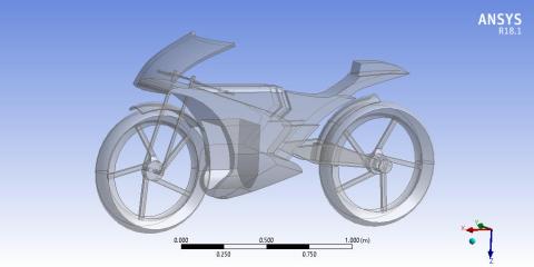
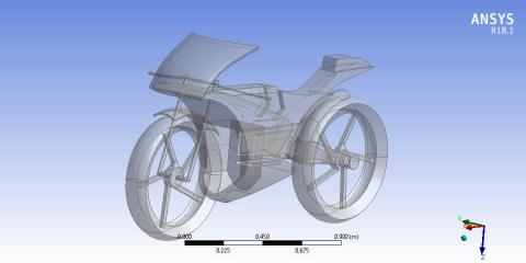
The model of the motorcycle was created using Creo Parametric, which is a parametric design software of a very robust modelling [31]. To start with, the design was drawn from the base sketch, and then the extrude tool was used to mold the basic structure. The pattern tool was then used to replicate this base model and modify it to create iterations of the motorcycle design [32]. These iterations were used to provide variations in design that could then be tested for aerodynamic improvement [33]. With this, the model was then exported to the .iges file format compatible with ANSYS DesignModeler, allowing for an easy transition between the design and simulation phases. The design models included two key variations: one without an opening in the engine bay (Figure 1) and one with a strategically designed opening in the engine bay (Figure 2). The addition of the opening was aimed at improving airflow dynamics within the engine compartment, potentially reducing pressure buildup and enhancing overall aerodynamic performance.
Figure 1. CAD model of the bike without an opening in the engine bay
Figure 2. CAD model of the bike with the opening in the engine bay
2.2 Importing and preparing the model for simulation
Once the CAD model was completed, it was imported into ANSYS DesignModeler (Figures 3 and 4). This step involved ensuring the model’s compatibility with the CFD analysis tools. The model was carefully checked for geometric errors, hard edges, and surface imperfections to prevent any inaccuracies during simulation. Geometric cleanup was performed where necessary to ensure that the model’s surfaces were smooth and free from defects that could interfere with the meshing and simulation process.
Figure 3. Importing a CAD model of the bike without opening it in the engine bay in ANSYS DesignModeler
Figure 4. Importing CAD model of the bike with the opening in the engine bay in ANSYS DesignModeler
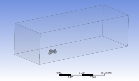
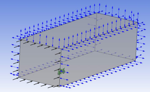
Once the import process was over, the computational domain was defined. A model of an enclosure around the motorcycle was created, with dimensions set so as to make the computational domain large enough to contain the entire aerodynamic flow without the introduction of boundary effects. According to the established guidelines for such simulations in literature [11], the computational domain was assigned the dimensions of 5 H1, 11 W, and 12 L, where H1 is the simulation domain’s height, W is the width, and L is the length. The surrounding enclosure is included in this model and is shown in Figure 5 to establish a proper simulation domain to adequately capture the flow interactions with the motorcycle.
Figure 5. Enclosure modelling in ANSYS DesignModeler
2.3 Meshing
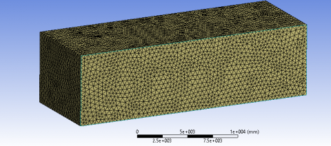
One of the most critical steps of CFD simulation is meshing, which discretizes the computational domain into elements over which fluid flow equations are computed [34]. Due to the complex geometry of the motorcycle, particular care was put into the meshing process to reach an accurate geometric representation. Meshing was done using tetrahedral elements owing to their shape agility to conform to the complex shapes of the motorcycle and the surrounding enclosure. Being polyhedra with four triangular faces, these elements are preferable for irregular shapes and offer a good compromise between computational efficiency and accuracy [35]. Figure 6 displays the resulting mesh that well resolves the fine details of the motorcycle and the surrounding flow field.
Figure 6. Meshed model in ANSYS DesignModeler
2.4 Boundary conditions and flow settings
An accurate simulation of CFD is very dependent upon using proper boundary conditions. To describe a real-world case of motorcycle operation, boundary conditions were set up as follows:
2.4.1 Inlet velocity
A velocity inlet with uniform velocity condition was applied at the domain inlet with an inlet velocity of 36 m/s. This velocity ensures that the velocities driven in the simulation are realistic and reflect forces acting upon a motorcycle at typical wind speeds encountered during high-speed motorcycle operation.
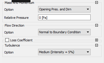
2.4.2 Outlet
The outlet condition of the domain was set as a pressure outlet with a fixed static gauge pressure (0 Pa) so that the spent airflow could freely exit the domain and impose no false restrictions, as shown in Figure 7.
Figure 7. Air outlet boundary conditions
Figure 8. Boundary conditions
Surface Boundary Conditions: The surface of the motorcycle was assumed in this case as a no-slip wall, which is to consider the friction and the boundary layer effect due to the fluid-solid surface interaction of the motorcycle. These boundary conditions, as shown in Figure 8, especially the use of uniform velocity inlet and pressure outlet, were chosen to match the real-world aerodynamic conditions so that the simulation results will be real-world and accurate.
2.5 Turbulence model selection
For evaluating flow across streamline bodies, open air environments, the turbulence intensity of 5% is preferred as per the ANSYS Fluent theory guide. The values are commonly adopted for CFD simulation of motorbikes and other vehicle types. At this turbulence intensity, the ambient disturbances, surface roughness effects do not have a significant effect on the aerodynamic characteristics of the bike [9, 11]. The simulation was performed using the Shear Stress Transport (SST) turbulence model because it is a robust model that effectively captures the flow behavior over complex geometries like those prone to motorcycle aerodynamics [36, 37]. The SST model combines k-ω model features in close proximity to the wall, with k-ε model features away from the wall, and is highly accurate in regions where boundary layer and flow separation are involved. The model is appropriate in predicting flow patterns around objects featuring adverse pressure gradients, including the motorcycle’s body and engine bay. In particular, the SST model is recognized for its ability to correctly predict flow separation and reattachment, which are vital parameters for assessing aerodynamic performance [38].
2.5.1 Solver settings and convergence criteria
In order to ensure the accuracy and reliability of the simulation results, the settings in the solver were adjusted for steady state analysis, since the aerodynamic forces applied to the motorcycle are generally time invariant in high-speed conditions. For discretizing the flow equations, the solver was set to use the Finite Volume Method (FVM). The convergence criterion was specified to ensure that the flow residuals dropped below 10-6 for all variables, indicating that the solution was sufficiently accurate.
The methodology described above allows the aerodynamic behavior of a motorcycle to be accurately simulated and analyzed, with a specific focus on the engine bay design. CAD model creation is done using Creo Parametric, meshing and simulation are done using ANSYS DesignModeler to ensure accuracy and consistency with industry standards. In order to be able to capture flow separation and boundary layer effects on complex geometry, the Shear Stress Transport (SST) turbulence model was selected [39]. The mesh was refined such that the aerodynamic features could be well represented, and the boundary layer was resolved suitably. Real-world operating conditions in a motorcycle were selected for boundary conditions, which make the simulation results relevant. By carefully implementing these settings and convergence, the methodology ensures that the simulation results of the motorcycle aerodynamics are both accurate and reliable as to allow evaluation of the impact of engine bay modifications.
In this section, Computational Fluid Dynamics (CFD) simulations are performed in two different designs of motorcycles; one that does not have an engine bay opening (Design 1) and another that has an engine bay opening (Design 2), and the results obtained from those simulations are discussed. Simulations were conducted at two different external airspeeds, 25 m/s and 36 m/s. The results of these simulations are providing the anticipation for pressure and velocity distributions, drag.
3.1 Without engine bay opening
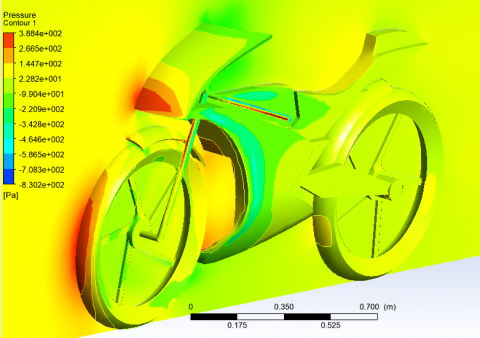
At an airspeed of 25 m/s, the pressure distribution for Design 1, which does not have an engine bay opening, is shown in Figure 9. The frontal section of the bike experiences much higher pressure than elsewhere on the bike, especially around the headlight and the front tyre. The highest pressure measured is 380 Pa. Meanwhile, the pressure at the rear section of the vehicle, at a location near the visor, is 140 Pa, showing that this part of the vehicle is experiencing relatively low pressure. This difference in pressure is crucial for understanding the aerodynamic forces acting on the vehicle.
Figure 9. Pressure distribution plot at 25 m/s air-speed
The pressure distribution is consistent with observations from the literature, as mentioned in the study [11], which supports the reliability of the CFD model. The pressure values obtained from the CFD analysis are in close agreement with previous findings, thereby validating the simulation results.
Figure 10. Velocity distribution plot at 25 m/s air-speed
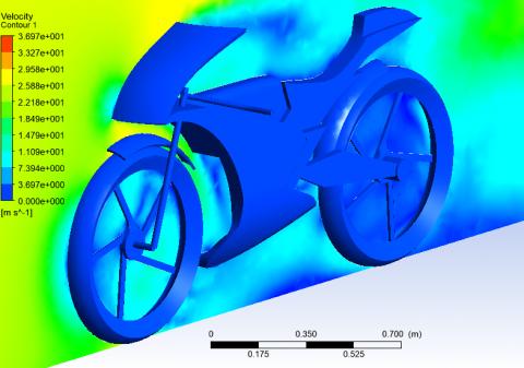
The velocity field across the midsection of the bike at 25 m/s is shown in Figure 10. The plot illustrates that the wind speed is higher in the front portion of the bike, particularly around the visor, where the velocity reaches a peak of 20.1 m/s. In contrast, the wind speed decreases significantly towards the rear of the bike, where it reaches a value of 10.02 m/s. This behavior is typical in aerodynamic simulations, as the flow tends to decelerate when encountering obstacles like the bike's body.
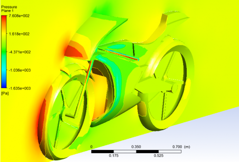
At a higher speed of 36 m/s, the pressure distribution for Design 1 is shown in Figure 11. The pressure in the frontal sections of the bike increases, with the maximum pressure reaching 752 Pa near the headlight and front tyre area. On the rear side of the vehicle, the pressure near the visor drops to 355 Pa, indicating a suction effect as the pressure becomes negative. This lower pressure at the rear contributes to the aerodynamic drag experienced by the bike.
Figure 11. Pressure distribution plot at 36 m/s air-speed
The velocity field for Design 1 at 36 m/s is shown in Figure 12. As expected, the highest velocity is observed near the bike's front, where the wind speed peaks at 30.35 m/s. The velocity gradually decreases towards the rear of the bike, where it reaches 15.17 m/s. This decrease in velocity from front to rear is typical in such simulations, as the airflow experiences resistance from the bike's body and components.
Figure 12. Velocity distribution plot at 36 m/s air-speed
3.2 With engine bay opening
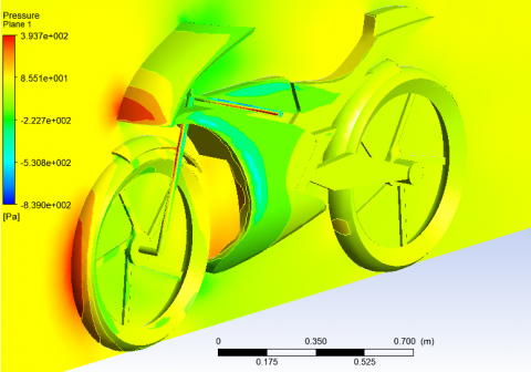
The pressure distribution for Design 2, which includes an engine bay opening, is shown in Figure 13 at an air-speed of 25 m/s. The maximum pressure in the frontal section is 385 Pa, similar to the pressure in Design 1, but the rear section shows a significant difference. The pressure at the rear of the vehicle near the visor is -84 Pa, which is negative and indicates a suction zone. This negative pressure suggests that the flow is separated and recirculating around the bike’s rear section due to the opening in the engine bay.
The velocity field across the midsection of the bike at 25 m/s is shown in Figure 14. The plot demonstrates that the wind speed near the front of the bike is higher than at the rear, with the highest velocity recorded at the front visor, reaching 22.1 m/s. At the rear zone, the velocity decreases to 11.15 m/s, confirming the expected aerodynamic behavior of the bike.
Figure 13. Pressure distribution plot at 25 m/s air-speed
Figure 14. Velocity distribution plot at 25 m/s air-speed
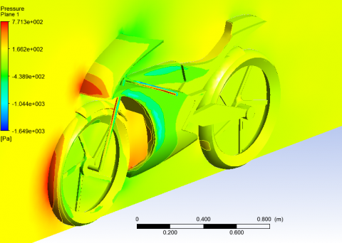
At 36 m/s airspeed, the pressure distribution plot for Design 2 is shown in Figure 15. The pressure in the frontal section is slightly higher than in Design 1, with a maximum pressure of 768 Pa near the headlight and front tyre. At the rear of the bike, the pressure is 435 Pa, again negative, which emphasizes the suction effect and enhanced flow separation due to the engine bay opening.
Figure 15. Pressure distribution plot at 36 m/s air-speed
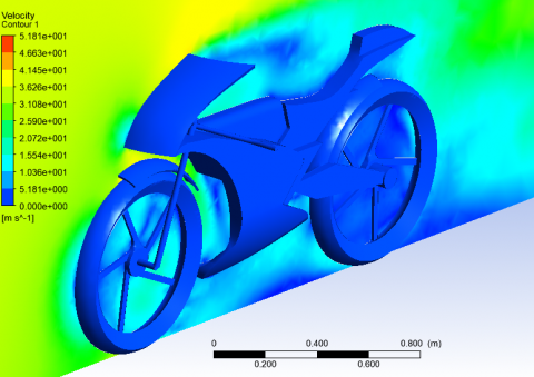
The velocity field for Design 2 at 36 m/s is shown in Figure 16. The velocity at the frontal section of the bike reaches a maximum of 32.6 m/s, which is higher than the velocity observed in Design 1. In the rear zone, the velocity is slightly higher than in Design 1, with a value of 15.4 m/s.
Figure 16. Velocity distribution plot at 36 m/s air-speed
From the pressure and velocity plots above, it is clear that the internal flow through the engine bay becomes more streamlined, showing accelerated internal velocities and enhanced flow reorganization around the rider’s body. As the air exits the engine bay and moves over the rear, the pressure field exhibits a more balanced gradient, and the velocity contours display smoother streamline transitions, reducing the extent of turbulent separation in the rear wake. These localized flow changes, particularly the redirection of flow through the mid-section and the mitigation of recirculation zones, play a central role in drag reduction. Even though the pressure drag is inherently higher at 36 m/s due to increased flow momentum, the design modifications ensure that the drag force increase is less steep than it would be with a fully blocked or non-optimized body configuration, limiting drag rise to just 1.19% at this higher speed. In essence, this interplay between localized high-pressure deceleration at the front and low-pressure acceleration at the rear, combined with the strategic internal flow guidance through the engine bay, validates the aerodynamic efficiency of the design.
It demonstrates how engineering refinements targeting local flow zones can yield measurable global aerodynamic improvements, supporting the integration of passive flow control features in future motorcycle designs. The engine bay internal flow improves its streamlines because it accelerates the internal speeds along with organizing the flow better around the rider. The rear pressure field achieves balance, and the velocity contours demonstrate smooth streamlines, which lead to reduced turbulence separation during the rear wake passage. The drag reduction process mainly relies on two local flow elements, which include flow redirection through the mid-area combined with decreased recirculation zone formation. At 36 m/s, the drag force increases measures only 1.19% despite higher pressure drag because the designed modifications prevent a dramatic drag force rise like a fully blocked body would experience. The present study shows that proper optimization of engine bay airflow produces quantifiable aerodynamic improvements, which result in lower induced pressure levels by 12.06% at 25 m/s and 11.53% at 36 m/s, as well as reduced drag force amounts by 1.64% at 25 m/s and 1.19% at 36 m/s. This internal flow management approach stands out against previously analyzed CFD-based aerodynamic studies.
On the other hand, Wiński and Piechna [11] performed an extensive CFD analysis of a sports motorcycle through complete body simulations to evaluate external surface pressures across the motorcycle and its drag performance. They discovered that rider position, together with fairing shape and wheel enclosure, controls drag forces by improving drag coefficient measurement results. Their study failed to analyze the internal flow patterns inside the engine bay, even though this area has previously received minimal attention for aerodynamic optimization. The present research demonstrates how opening the engine bay for ventilation serves as a natural means for reducing turbulence and recovering pressure while preserving the structural framework. Also, Cravero et al. [20] conducted a study of a race car wheel setup to analyze external front wing aerodynamics between multiple elements. Research finds that specific design changes in the vicinity of rotating elements alter both wake formations and pressure drag phenomena. The researchers provide valuable insights for automotive aerodynamics through external modifications to vehicle surfaces, but their research stops at the point where internal flows for drag reduction are concerned.
In contrast, this study pioneers a novel design pathway by treating the engine bay as a functional aerodynamic channel, redistributing pressure and improving internal airflow alignment with external streamlines. This not only mitigates turbulent wake formation but also provides insight into integrated aerodynamic optimization, where internal and external flows are co-engineered to reduce drag. Thus, the current work builds upon established CFD methodologies while extending their scope through engine bay airflow manipulation, offering a new dimension of performance enhancement in motorcycle design that is underrepresented in existing literature.
3.3 Pressure and drag force comparison
The pressure and drag force comparison at 25 m/s air-speed is shown in Table 1. The design with the engine bay opening (Design 2) shows a 12.06% reduction in induced pressure compared to Design 1. This reduction in pressure leads to a 1.64% decrease in the induced drag force, demonstrating the effectiveness of the engine bay opening in reducing aerodynamic drag.
Table 1. Pressure and drag force comparison at 25 m/s
|
Design Type |
Pressure (Pa) |
Drag Force (N) |
|
Design 1 (no engine bay opening) |
91.2 |
103.1 |
|
Design 2 (engine bay opening) |
80.2 |
101.4 |
Similarly, at 36 m/s air speed, the design with the engine bay opening shows an 11.53% reduction in induced pressure, resulting in a 1.19% decrease in induced drag force when compared to Design 1 in Table 2.
Table 2. Pressure and drag force comparison at 36 m/s
|
Design Type |
Pressure (Pa) |
Drag Force (N) |
|
Design 1 (no engine bay opening) |
178.96 |
203.58 |
|
Design 2 (engine bay opening) |
158.31 |
201.14 |
The obtained reduction of pressure is significant as it reduces the pressure fluctuations on the rear and side profiles of the motorcycle. The reduction in air pressure enables the improvement of vehicle stability and thus handling. It also mitigates strain on engine power, which allows better acceleration response and attaining higher top speeds. As per aerodynamic principles, even a 1.19% drag reduction enhances fuel economy by 0.5 km/l to 1 km/l, depending upon riding conditions and engine efficiency. For long distances, this translates into significant fuel cost savings as well as lower emissions.
External rapid airflow through the engine bay supports passive ventilation, which helps remove heat from the combustion engine block, radiator, as well as exhaust components. The passive cooling system functions to decrease thermal loads while neglecting the need for active cooling needs thus it keeps designs simple and minimizes system weight. These openings demonstrated increased effectiveness at 36 m/s because the convective heat transfer coefficients increase from the air velocity combined with the pressure differential across the bay. The improved heat dissipation of this design, combined with aerodynamic enhancements, thus brings dual advantages, i.e., reducing drag and enhancing cooling within the system.
3.4 Grid independence test and validation
To ensure the reliability and accuracy of the CFD results, a Grid Independence Test was performed. The results of the test are summarized in Table 3, which shows the pressure values obtained with different mesh sizes. The test indicates that the mesh with 135,689 elements provides a stable pressure value of 380.1 Pa, 0.28 skewness, and average aspect ratio of 2.0, indicating grid independence. This confirms that the results are not significantly affected by the mesh resolution and that the solution is independent of further mesh refinement.
Table 3. Grid independence test
|
Number of Elements |
Pressure (Pa) |
Maximum Skewness |
Average Aspect Ratio |
|
134810 |
378.54 |
0.32 |
2.3 |
|
134987 |
379.95 |
0.30 |
2.1 |
|
135502 |
380.09 |
0.29 |
2.2 |
|
135689 |
380.1 |
0.28 |
2.0 |
The pressure and velocity results from the CFD analysis are in close agreement with theoretical expectations and experimental observations presented in the literature [11]. This further validates the CFD approach employed in this study.
The CFD results clearly demonstrate the aerodynamic benefits of an engine bay opening in motorcycle design. The design with the engine bay opening (Design 2) also has a pressure and drag force reduction in both the 25 m/s and 36 m/s simulations compared to the design without the opening (Design 1). The induced pressure on the bike was reduced by 12.06% at 25 m/s and 11.53% at 36 m/s, while the drag force diminished by 1.64% and 1.19%, respectively. This implies that the opening of the engine bay enhances aerodynamic efficiency. The further findings from these results are supported by the velocity field: higher velocities near the front and lower velocities at the rear, as would be expected for aerodynamic behavior. By introducing the engine bay opening, pressure buildup in the rear region is alleviated, opening a suction zone that provides a drag reduction contribution. In addition, the expected flow separation when travelling at a high speed corresponds with a region of negative pressure near the bike’s rear, which reduces drag. The results of the Grid Independence Test demonstrated the robustness of results with respect to mesh refinement, proving the quality of results. Furthermore, the pressure distributions and drag reductions generated are logical with the concepts of aerodynamic design, as optimal flow around the body decreases drag and enhances overall stability. These results are consistent with aerodynamic theory well established in literature and infer that modifying the engine bay may be a viable way to enhance motorcycle performance, including reducing drag and enhancing stability. An additional area of future studies might be to further develop optimizations of the engine bay opening for even greater benefits of aerodynamics.
This study aimed to examine the influence of engine bay openings on motorcycle aerodynamic performance in the form of pressure distribution, velocity fields, and drag reduction. Two design configurations were tested using Computational Fluid Dynamics (CFD) simulations to test the enhancement strategy; one with an open engine bay and the second with better airflow by omitting an engine bay cover. The CFD results validated the hypothesis stating that the introduction of an engine bay opening would reduce pressure and drag force. Primary findings demonstrated that the designed opening of the engine bay led to a decrease of induced pressure by 12.06 and 11.53 percent (at 25 m/s and 36 m/s, respectively), resulting in a decrease of drag force by 1.64 and 1.19 percent (at the same speeds, respectively). Moreover, the analysis of the velocity field revealed a more efficient flow around the bike and the formation of a suction zone at the rear, which confirms improved aerodynamic behavior. While the results are promising, the study has some limitations in terms of the boundary conditions and assumptions used in the simulations, including the assumption of uniform inlet velocities as well as not including real-world factors like wind variability or terrain effects. Further work in the future can turn to more dynamic conditions, to include, for example, given wind speeds, various terrains, or even real-world testing to confirm CFD predictions. Moreover, with additional iterations of the engine bay opening, it would be possible to investigate alternative configurations for enhanced aerodynamic performance. Overall, the findings support the hypothesis and statements of this research on how engineering design changes to the engine bay can improve a motorcycle’s aerodynamic efficiency. Based on this study, the findings can be used as a good foundation for further aerodynamic optimizations in the design of motorcycles, as they can be applied to optimize fuel efficiency, stability, and performance of motorcycles.
[1] Martin, E., Courtright, T., Nkurunziza, A., Lah, O. (2023). Motorcycle taxis in transition? Review of digitalization and electrification trends in selected East African capital cities. Case Studies on Transport Policy, 13: 101057. https://doi.org/10.1016/j.cstp.2023.101057
[2] Crouch, T.N., Burton, D., LaBry, Z.A., Blair, K.B. (2017). Riding against the wind: A review of competition cycling aerodynamics. Sports Engineering, 20: 81-110. https://doi.org/10.1007/s12283-017-0234-1
[3] Mariaprakasam, R.D.R., Mat, S., Samin, P.M., Othman, N., Wahid, M.A., Said, M. (2023). Review on flow controls for vehicles' aerodynamic drag reduction. Journal of Advanced Research in Fluid Mechanics and Thermal Sciences, 101(1): 11-36. https://doi.org/10.37934/arfmts.101.1.1136
[4] Camara, A. (2021). Vehicle-bridge interaction and driving accident risks under skew winds. Journal of Wind Engineering and Industrial Aerodynamics, 214: 104672. https://doi.org/10.1016/j.jweia.2021.104672
[5] Nakashima, T., Mutsuda, H., Kanehira, T., Tsubokura, M. (2020). Fluid-dynamic force measurement of the Ahmed model in steady-state cornering. Energies, 13(24): 6592. https://doi.org/10.3390/en13246592
[6] Angeletti, M., Sclafani, L., Bella, G., Ubertini, S. (2003). The role of CFD in the aerodynamic investigation of motorcycles. SAE Transactions, 112: 1103-1111. https://www.jstor.org/stable/44745486.
[7] Blocken, B., Toparlar, Y. (2015). A following car influences cyclist drag: CFD simulations and wind tunnel measurements. Journal of Wind Engineering and Industrial Aerodynamics, 145: 178-186. https://doi.org/10.1016/j.jweia.2015.06.015
[8] Garg, M., Jayaram, N. (2022). Simulation-Driven Aerodynamic Development of a High-Performance Motorcycle. SAE Technical Paper, No. 2022-32-0112. https://doi.org/10.4271/2022-32-0112
[9] Takahashi, Y., Kurakawa, Y., Sugita, H., Ishima, T., Obokata, T. (2009). CFD analysis of airflow around the rider of a motorcycle for rider comfort improvement. SAE Technical Paper, No. 2009-01-1155. https://doi.org/10.4271/2009-01-1155
[10] Agarwal, A., Mthembu, L. (2022). Investigation of dynamic factors in different sections of HVC by static and free vibration modal analysis. Annales de Chimie - Science des Matériaux, 46(2): 75-84. https://doi.org/10.18280/acsm.460203
[11] Wiński, K., Piechna, A. (2022). Comprehensive CFD aerodynamic simulation of a sports motorcycle. Energies, 15: 5920. https://doi.org/10.3390/en15165920
[12] González-Arcos, B., Gamez-Montero, P.J. (2023). Aerodynamic study of MotoGP motorcycle flow redirectors. Energies, 16: 4793. https://doi.org/10.3390/en16124793
[13] Sharma, M., Hussain, D. (2020). An investigative study on motorbike through CFD solar. In Proceedings of International Conference in Mechanical and Energy Technology: ICMET 2019, India, pp. 195-208. https://doi.org/10.1007/978-981-15-2647-3_18
[14] Van Dijck, T. (2015). Computational evaluation of aerodynamic forces on a racing motorcycle during high-speed cornering. SAE Technical Paper, No. 2015-01-0097. https://doi.org/10.4271/2015-01-0097
[15] González, B., Vasquez, F. (2023). Influence of aerodynamic lift and centre of pressure position on motorcycle stability. In The Evolving Scholar-BMD 2023, 5th Edition. http://doi.org/10.59490/6504e3dbed8b8577378bc1bc
[16] Schröter, K., Pleß, R., Seiniger, P. (2016). Vehicle dynamics control systems for motorcycles. In Handbook of Driver Assistance Systems, Springer International Publishing, pp. 969-1006. https://doi.org/10.1007/978-3-319-12352-3_42
[17] Bilge, E. (2011). Thermal management concept of a taxi vehicle with rear engine application. In Vehicle Thermal Management Systems Conference and Exhibition (VTMS10), Elsevier, pp. 491-500.
[18] Szudarek, M., Piechna, J. (2021). CFD analysis of the influence of the front wing setup on a time attack sports car’s aerodynamics. Energies, 14(23): 7907. https://doi.org/10.3390/en14237907
[19] Malizia, F., Blocken, B. (2021). Cyclist aerodynamics through time: Better, faster, stronger. Journal of Wind Engineering and Industrial Aerodynamics, 214: 104673. https://doi.org/10.1016/j.jweia.2021.104673
[20] Cravero, C., Marsano, D. (2022). Computational investigation of the aerodynamics of a wheel installed on a race car with a multi-element front wing. Fluids, 7(6): 182. https://doi.org/10.3390/fluids7060182
[21] van Druenen, T., Blocken, B. (2024). CFD simulations of cyclist aerodynamics: Impact of computational parameters. Journal of Wind Engineering and Industrial Aerodynamics, 249: 105714. https://doi.org/10.1016/j.jweia.2024.105714
[22] Palanivendhan, M., Nagpal, D., Ayush Rao, D., Philip, J., Srinivas Ganapathi, M. (2021). Design and analysis of an aerodynamic kit for a two-wheeled race motorcycle. Materials Today: Proceedings, 45: 7239-7246. https://doi.org/10.1016/j.matpr.2021.02.635
[23] Blocken, B., van Druenen, T., Toparlar, Y., Andrianne, T. (2018). Aerodynamic analysis of different cyclist hill descent positions. Journal of Wind Engineering and Industrial Aerodynamics, 181: 27-45. https://doi.org/10.1016/j.jweia.2018.08.010
[24] Wang, S., Pitman, J., Brown, C., Tudball Smith, D., Crouch, T., Thompson, M.C., Burton, D. (2021). The influence of the inter-relationship of leg position and riding posture on cycling aerodynamics. Fluids, 7(1): 18. https://doi.org/10.3390/fluids7010018
[25] Gromke, C., Ruck, B. (2021). Passenger car-induced lateral aerodynamic loads on cyclists during overtaking. Journal of Wind Engineering and Industrial Aerodynamics, 209: 104489. https://doi.org/10.1016/j.jweia.2020.104489
[26] Blocken, B., Toparlar, Y., Andrianne, T. (2016). Aerodynamic benefit for a cyclist from a following motorcycle. Journal of Wind Engineering and Industrial Aerodynamics, 155: 1-10. https://doi.org/10.1016/j.jweia.2016.04.008
[27] Ferdaus, F., Raghukiran, N. (2021). Aerodynamic performance improvement by streamlining the front fairing of a racing vehicle. IOP Conference Series: Materials Science and Engineering, 1128(1): 012007. https://doi.org/10.1088/1757-899X/1128/1/012007
[28] Mukut, A.N.M.M.I., Abedin, M.Z. (2019). Review on aerodynamic drag reduction of vehicles. International Journal of Engineering Materials and Manufacture, 4(1): 1-14. https://doi.org/10.26776/ijemm.04.01.2019.01
[29] Brown, Y.I., Windsor, S., Gaylard, A.P. (2010). The effect of base bleed and rear cavities on the drag of an SUV. SAE Technical Paper, No. 2010-01-0512.
[30] Huang, Y., Wang, S., Ji, Y., Liu, Z. (2021). Study of the automotive aerodynamic performance affected by the entrance structure of the forecabin. Energy and Built Environment, 2(3): 327-335. https://doi.org/10.1016/j.enbenv.2020.06.012
[31] Agarwal, A., Kalenga, M.K.W., Ilunga, M. (2025). CFD simulation of fluid flow and combustion characteristics in aero-engine combustion chambers with single and double fuel inlets. Processes, 13(1): 124. https://doi.org/10.3390/pr13010124
[32] Muzawi, R., Irawan, Y., Akhiyar, D., Setiawan, D. (2022). Pattern lock and GPS-based motorcycle security system. International Journal of Engineering Trends and Technology, 70(3): 185-194. https://doi.org/10.14445/22315381/IJETT-V70i3p221
[33] Agarwal, A., Dinka, M.O., Ilunga, M. (2024). Enhancing engine cylinder heat dissipation capacity through direct optimization (DO) techniques. Processes, 12(12): 2659. https://doi.org/10.3390/pr12122659
[34] Hamdaoui, M.A., Benzaama, M.H., El Mendili, Y., Chateigner, D. (2021). A review on physical and data-driven modeling of buildings' hygrothermal behavior: Models, approaches, and simulation tools. Energy and Buildings, 251: 111343. https://doi.org/10.1016/j.enbuild.2021.111343
[35] Meyer, W. (2006). Graphs, maps, and polyhedra. In Geometry and Its Applications, Elsevier, pp. 379-457.
[36] Agarwal, A., Ilunga, M., Tempa, K., Humagai, B.K. (2024). CFD analysis of solar air heater using V-shaped artificial roughness to attain heat transfer enhancement. International Journal of Energy Production and Management, 9(3): 171-180. https://doi.org/10.18280/ijepm.090306
[37] Menter, F.R. (2009). Review of the shear-stress transport turbulence model experience from an industrial perspective. International Journal of Computational Fluid Dynamics, 23(4): 305-316. https://doi.org/10.1080/10618560902773387
[38] Musinguzi, W.B., Yu, P. (2023). Enhanced thermal performance of shell and tube heat exchangers using TiO2/water nanofluids: An SST turbulence model analysis. Journal of Sustainability for Energy, 2(3): 154-164. https://doi.org/10.56578/jse020305
[39] Agarwal, A., Letsatsi, M.T., Pitso, I. (2021). Thermodynamic analysis of wind catcher with cooling pads using SSG Reynolds stress turbulence model. Journal of Engineering Research, 9(1): 1-13. https://doi.org/10.36909/JER.ICIPP