Hasan A. Mohammed | Ahmed Nasser B. Alsammak*
© 2025 The authors. This article is published by IIETA and is licensed under the CC BY 4.0 license (http://creativecommons.org/licenses/by/4.0/).
OPEN ACCESS
The nature of the electrical power system is dynamic, not static. The stability, reliability, and quality of electrical power are considered among the most essential requirements of the consumer, as the electrical power system has become a huge one due to the increasing demand for electrical energy. The electrical system is often subject to malfunctions and various types of external or internal faults. It is necessary to find an appropriate and effective way to avoid the adverse effects of these faults and mitigate system losses resulting from them. Many methods have been used to reduce the value of the high fault current. One of these methods is the Fault Current Limiter (FCL), which depends on its work in adding impedance to the line in order to reduce the fault current. The Solid State Fault Current Limiter (SSFCL) depends on exploiting the benefits of power electronics switches with rapid response and is used as a protection device; it can also reduce the cost of protection equipment and reduce the short circuit level. This work examined and evaluated the effect of SSFCL Matlab-Simulink, where the results show that SSFCL effectively decreases fault current from 96% to 96.7% for all fault types.
power electronics switches, power electronics converters, Fault Current Limiter, solid-state, FLC, SSFLC, transient stability
Rising energy demand requires more efficient electrical equipment and better power system interconnection. This can lead to fault currents exceeding capacity, risking damage to protective devices. Upgrading substation equipment is costly and time-intensive. Methods to mitigate fault currents include bus splitting, which adds grid complexity, and current limiting reactors, which cause voltage drops and affect efficiency and power factor. Fault Current Limiters effectively reduce fault current, enhancing system stability and allowing the use of lower-rated protective device [1].
Generally, when a fault current occurs, the circuit breaker automatically disconnects the circuit within 3 to 6 cycles. However, certain switches are incapable of managing elevated short-circuit current levels, as they are engineered to endure a lower magnitude of fault current. Consequently, these switches may fail to disrupt the circuit, potentially resulting in system failures. Modern power switching methods for short circuit currents utilize static Fault Current Limiters, providing an effective solution for transmission and distribution systems by alleviating problems caused by substantial fault currents inside the system [2].
Static Fault Current Limiters improve the operational conditions for downstream equipment by reducing the fault current [3].
To effectively interrupt current, static Fault Current Limiters must integrate energy-absorbing devices. These limiters reduce thermal and dynamic stresses, thus decreasing fault current [4]. Static switches with high-power semiconductors offer benefits over mechanical switches in speed and lifespan. Voltage quality during short circuits improves by reducing fault current, limiting a three-phase fault duration to 100 ms [5].
Managing short circuits is vital for improving power quality in medium voltage networks and is crucial for networks supplying new customers. Power electronic devices enhance network power quality and support renewable electricity integration [6].
Power electronics elements are exploited to protect the electrical power system and improve transient stability through FACTs elements, as they are characterized by high speed in the switching mechanism [7].
Transient stability can be improved by relying on modern control methods, such as Fuzzy, Neural, and ANFIS, to generate the magnitudes of the power electronics elements used in FACTs [8].
The electrical system is protected using distance relays based on exploiting the speed of response of the power electronics elements, thus avoiding the system from high currents that have a negative impact on the electrical power equipment [9].
It is possible to protect the distribution side of the electrical power system and improve the quality of electrical power as well, relying on the exploitation of inverters and power electronics elements with rapid response and with different control methods, traditional, modern, or hybrid [10, 11].
Some recent research discusses improving the quality of electrical power and transient stability by using intelligent control methods such as Fuzzy to control the stabilizer unit of the synchronous generator [12].
Static device solutions face high costs and power dissipation in conductive parts, limiting their use in power circuit breakers. Reducing prices and power losses can improve adoption. Power semiconductors have the ability to reduce voltage distortions and short-circuit currents [13]. High-power semiconductors like thyristors with gate extinguishing capabilities replace mechanical switches. Before devices like Gate Turn-Off Thyristors (GTOs) or Insulated Gate Bipolar Transistors (IGBTs), conventional thyristors were part of forced switching switches. Forced-switching thyristor circuit breakers are complex yet longstanding in power conversion and have limited switching frequencies and complex command schemes. For static switches, high-frequency switching is less crucial. Thyristors are mainly disadvantaged in blocking, achieved via forced extinction or reduced current below holding current [14].
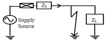
The single-line diagram shown in Figure 1, is the equivalent circuit of the electrical power system with its basic components represented by the source impedance (ZS), load impedance (ZL), and fault.
Figure 1. Single line diagram of FCL
The circuit current in a normal condition is the ratio of the voltage value to the total circuit impedances, as shown in Eq. (1).
$I=\frac{V_s}{\left(Z_s+Z_L\right)}$ (1)
When a fault occurs, the circuit current will increase due to the decrease in impedance, as shown in Eq. (2).
$I=\frac{V_s}{\left(Z_s\right)}$ (2)
When the system is subjectd to a specific fault, the value of the fault current will be much higher than its value in the normal case. The reason is that the load impedance is excluded from the current calculation equation because it is connected in parallel with a short circuit, and the value of the source impedance is much less than the load impedance.
There is another type of FCL, which is also often used in high voltage power systems and distribution line power systems, called the hybrid FCL; this limiter consists of a superconductivity element connected in parallel with two branches, the first of which consists of an inductance that works to reduce the fault current and the second branch consists of an IGBT transistor that works to reduce the temperature of the superconductive element and it can be compensated for a superconducting element in the second mode [15].
For HVDC systems, the fault protection mechanism is a hybrid system consisting of a DC circuit breaker connected in parallel with the FCL system. This process is, therefore, much more expensive and complex than for low or medium-voltage systems [16, 17].
In this work, the benefit of Solid State Fault Current Limiter (SSFLC) was exploited to improve the stability of the electrical power system when the system is subjectd to any electrical disturbances, as the rapid response of the power electronics elements works to add inductive impedance to the transmission line very quickly compared to previous works that relied on traditional circuit breakers in their work. The modeling results have proven the effectiveness of this proposed system by improving the transient response represented by improving the rotor angle of the synchronous generator.
Various classifications of FCLs exist, designed to restrict the magnitude of fault currents. The classification is divided into two categories, determined by the differing techniques employed to limit fault current magnitude. These categories include Steady State Fault Current Limiters (FCL) and Superconducting Fault Current Limiters.
Various FCLs exist, with four specific types outlined here: Fault Current Reactor, Superconducting Fault Current Limiter, Pyrotechnic Fault Current Limiter, and solid-state Fault Current Limiters (SSFCL) [18].
2.1 FCL reactor
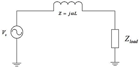
An FCL reactor is a standard method for reducing fault currents. This method is used with short and medium transmission lines and consists of adding a coil to the transmission line when a specific fault occurs, as shown in Figure 2. One of the properties of this coil is that it has a high inductive impedance and a small resistance [19].
Figure 2. Fault current limiting reactor
The value of the inductive resistance is not affected by magnetic saturation; thus, this resistance is not dependent on the current value. The advantages of this method are the low cost and low maintenance, but it suffers from a loss of power, a voltage drop, and a low power factor.
2.2 SFCL
Superconducting materials can transmit electricity without resistance when chilled beneath their critical temperature. Under regular working conditions, the FCL temperature is maintained below the critical threshold. Therefore, it presents minimal resistance under typical situations. During a short circuit, when the current magnitude escalates, the material's temperature surpasses its critical threshold. The impedance offered by the FCL markedly increases, limiting the fault current's value.
This type has many disadvantages, such as high power consumption and significant losses, high cost compared to other types of current limiters, and it requires a relatively long time of approximately (10 to 15) minutes to return to work after the fault occurs and reduce the current [20].
2.3 Pyrotechnic Fault Current Limiters (Is-Limiter)
The Is-limiter is another way to reduce the fault current. In this method, a conductor is used in series with a high-speed electrical switch but does not withstand high fault currents. The key and switch are connected in parallel with a fuse that melts when its current reaches a specific value.
When a fault occurs, the switch will open, causing current to pass through the parallel fuse circuit. The Is-limiter contains an electronic device responsible for the controller's action based on the current value passing through the system, as it measures the current instantaneously.
The Is-limiter contains an electronic device responsible for the controller's action based on the value of the current passing through the system, as it measures the current instantaneously. The advantages of the IS-Limiter are that it identifies the fault at the fault location, connects the generator independently, and has nothing to do with the short circuit level, on the other hand, this limiter requires an external pulse to operate the switch, and this controller is also not resetting [21].
2.4 SSFCL
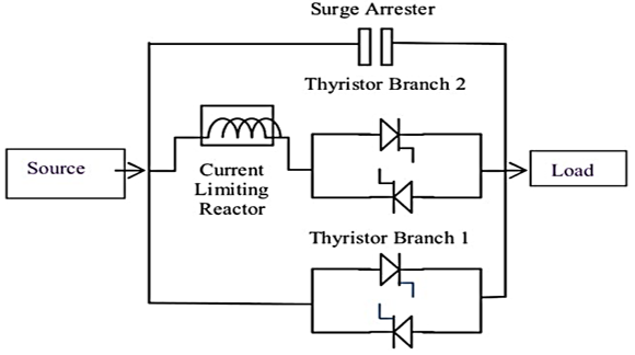
Solid-state devices, including IGBT, ETO, GTO, IGCT, and other similar components, are employed in SSFCL to restrict fault current levels. An SSFCL facilitates the current bypass through the semiconductor switches by supplying the gate pulse during standard operational conditions. In the event of a fault condition, the semiconductor switches direct the fault current through the impedance branch, thereby limiting the fault current to an acceptable level, which results in the opening of the circuit breakers.
A hybrid SSFCL system can be used, consisting of three branches. The first branch consists of a series circuit breaker with an AC inverter, which relies on power electronics components and operates under normal operating conditions. The second branch consists of an FCL, which operates under abnormal conditions and faults. The third branch contains the MOV, which absorbs high energy during faults. This circuit is more complex than a conventional SSFCL due to the large number of components used, which complicates the pulses mechanism for power electronics components, as well as the high cost [22].
SSFCL operates as a variable-impedance apparatus incorporated in series with a circuit to limit current flow during fault conditions. The SSFCL is designed to exhibit low impedance during standard operational conditions and will be high in fault conditions. Based on the aforementioned characteristics, multiple types of Fault Current Limiters (FCLs) have been developed, leveraging the advantages provided by the rapid response of power electronic switches [23].
Fault current limitation technology has emerged as a critical issue and a focal point in power system protection research focusing on superconducting and power electronic switch kinds of Fault Current Limiters (FCL), with solid-state FCL demonstrating superior performance. SSFCL offers numerous benefits for flexibility and reliability while also decreasing the costs of protective equipment and mitigating short circuit levels [24].
In order for the performance of the SSFCL controller to be ideal, it must work to add a very high value of impedance to the system in the fault case, while the added resistance is zero in the normal case. The specifications of an ideal SSFCL is the speed of response to reduce the fault current during the first cycle of the current wave, as well as the speed of returning the circuit to regular operation and removing the added impedance after the fault disappears [25].
In the case of the use of traditional circuit breakers, the fault current will completely destroy the components of the system because it takes (2-3) seconds to work. Therefore, circuit breakers are used based on static semiconductor elements with fast response, which is represented by SSFCL as shown in Figure 3, the controller circuit consists of two converters. The first converter works in normal conditions, while the second converter works in fault conditions. The first converter will stop working, and the second modulator will work to decrease the fault current due to the presence of an impedance connected to this converter in series [26].
Figure 3. Solid state FCL
The impedance of the controller can be calculated through Eq. (3).
$Z_{F C L}=2 \pi f L=\frac{V}{I_{F C L}}$ (3)
where, ZFCL is the impedance of FCL, LFCL is the inductance of FCL, IFCL is the flow current of FCL, and V is the system source voltage.
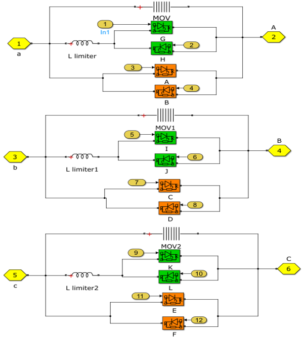
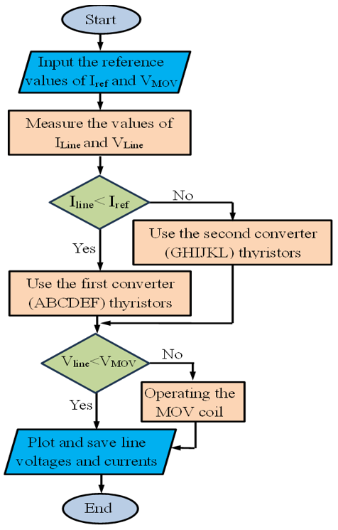
SSFCL system consists of two power electronics converters, which depend on power electronics elements in their operation, as shown in Figure 4. The principal operation of SSFCL can be explained in two scenarios:
The first scenario: In normal operation conditions, if there is no fault, the system will operate normally depending on the first converter in a natural way, which depends on (ABCDEF) thyristors.
The second scenario: When the system is subjected to an external fault, which leads to an increase in the current passing through the circuit, the value of (Iref), this will lead to turning off the first converter and the second converter (GHIJKL) thyristors will be operated, this converter is specialized to protect the system from high currents.
The control circuit was provided with MOV, which operates at a voltage of 500 MV, has two columns, and a reference current of 500 A for each column. The function of using MOV is to determine the value of the null within acceptable limits. The principal operation of SSFCL is illustrated in a flow chart, as shown in Figure 5.
Figure 4. SSFCL converters
Figure 5. The flow chart of the operation of SSFCL
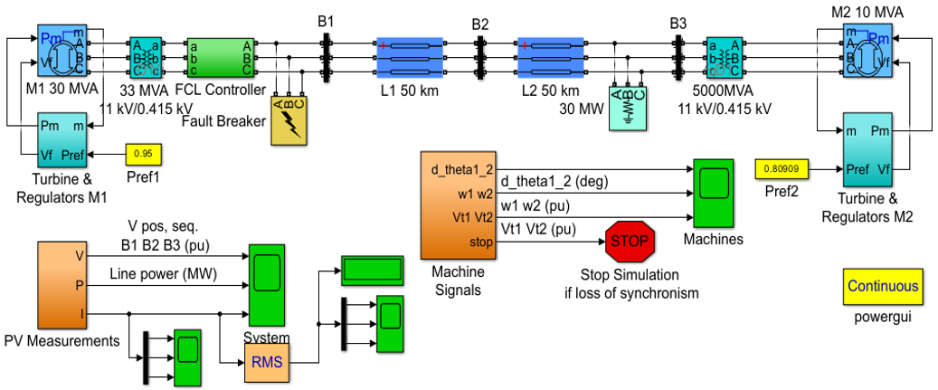
The proposed system consists of two two-generation units with a heavy load to explain the impact of SSFCL on the system's rotor angle response. It consists of two synchronous generators; the first generator with rated at 30 MVA, 11 kV, and 50 Hz, while the second generator's capacity is 10 MVA, 11 kV, and 50 Hz. Also, it consists of two power transformers 33 MVA, that converts the voltages from 11 kV into 0.415 kV. The transmission line operates at a voltage of 0.415 kV, 100 km long, with a resistance of 0.01755 pu/km and an inductance of 0.0008737 pu/km; the load is 30 kW. This system has been simulated using MATLAB Simulink, as shown in Figure 6.
Figure 6. The Simulink circuit of the tested power system
The SSFCL's control circuit consists of a three-phase AC-to-AC converter. Each phase consists of two IGBT transistors with anti-parallel connections and a 180-degree phase difference between them. That is, when the forward angle of the transistor is 0-degree, the second transistor's angle will be 180-degree. There is a 120-degree phase difference between this phase and the next phase and 240-degree with the third phase.
To study the effectiveness of the SSFCL, The results of three important variables were taken: the voltages of the three lines, the currents of the three lines, and the rotor angle of the synchronous generators with and without this controller, and when the system was subjectd to four types of faults: Single line to ground (L-G) fault, line to line (L-L) fault, double line to ground (L-L-G) fault and three line to ground (3L-G) fault,
4.1 Single line to ground (L-G) fault
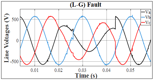
The line voltage waveforms when the system is subjected to (L-G) fault are shown in Figure 7; from this Figure, it can be seen the amount of drop as well as the distortion in the line voltages as a result of this fault.
Figure 7. Line voltages during (L-G) fault without SSFCL
This voltage negatively affects the quality of power and performance of the system. It is necessary to improve the voltage waveform and operate at the rated values.
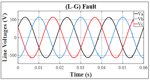
The voltage waveform has been improved, and distortions have been eliminated with SSFCL, as shown in Figure 8.
Figure 8. Line voltages during (L-G) fault with SSFCL
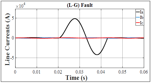
The line current has increased to 47500 A when a (L-G) fault occurs in the absence of the SSFCL, as explained in Figure 9.
Figure 9. Line currents during (L-G) fault without SSFCL
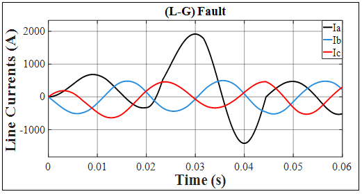
This current has decreased to 1900A, with a reduction rate of 96% using SSFCL and an error margin of 0.001%, as shown in Figure 10.
Figure 10. Line currents during (L-G) fault with SSFCL
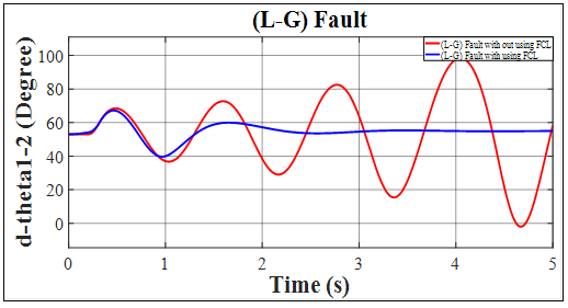
The effect of the SSFCL controller on system stability when the system is subjected to (L-G) fault is also studied by measuring the difference in rotor angles (dθ1-2) for the two generator units, as shown in Figure 11. This figure shows that the system is unstable when it is subjected to a fault and in the event that the SSFCL is not used (the red curve), while the system works stably in the case of using SSFCL (the blue curve). Through this form, the importance of using SSFCL in this work can be proven.
Figure 11. Difference in rotor angles during (L-G) Fault
4.2 Line to line (L-L) fault
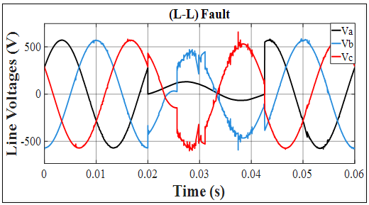
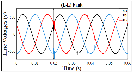
The line voltage waveforms when the system is subjected to (L-L) fault are shown in Figure 12. From this Figure, it can see the amount of drop, as well as the distortion in the line voltages when the fault occurs, where the voltage drops falls to less than 20% of the rated voltage value.
Figure 12. Line voltages during (L-L) fault without SSFCL
The importance of using SSFCL can be seen in the shape of the line voltages and the three phases, as they have become sinusoidal and free of distortions, as shown in Figure 13.
Figure 13. Line voltages during (L-L) fault with SSFCL
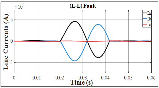
As for the line currents, they are affected by the fault, as shown in Figure 14, where the current value increases very significantly, reaching 45000 A in the absence of the SSFCL. This value is very dangerous and leads to damage to the system.
Figure 14. Line currents during (L-L) fault without SSFCL
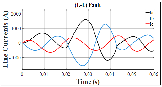
The line current is significantly reduced from 45000A to 1500A by using SSFCL, with a reduction rate of approximately 96.7%, with an error margin of 0.03%, as shown in Figure 15. From this figure, it can seen the importance of using SSFCL in this system.
Figure 15. Line currents during (L-L) fault with SSFCL
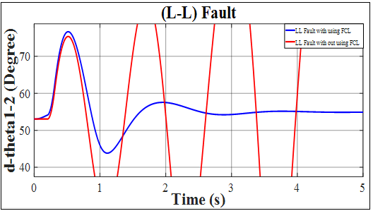
The influence of SSFCL operation on system stability by measuring the dθ1-2 of the synchronous generator when the system is subjected to (L-L) fault, as shown in Figure 16.
This figure shows that the system is unstable when it is subjected to a fault and in the event that the SSFCL is not used (the red curve), while the system works stably in the case of using SSFCL (the blue curve). The simulink results demonstrated the controller's effectiveness in stabilizing the system and maintaining normal operation.
Figure 16. Difference in rotor angles during (L-L) fault
4.3 Double line to ground (L-L-G) fault
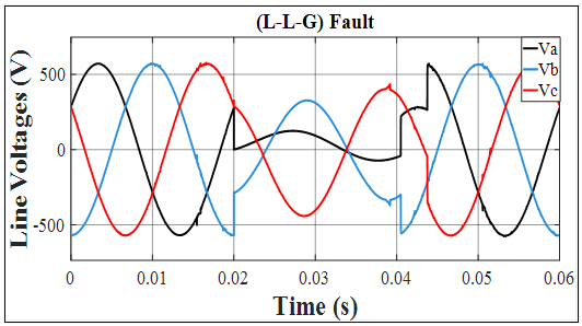
The line voltage waveforms when the system is subjected to (L-L-G) fault are shown in Figure 17. From this figure, it can be seen the amount of drop, as well as the distortion in the line voltages as a result of this fault, and the system is working abnormally.
Figure 17. Line voltages during (L-L-G) fault without SSFCL
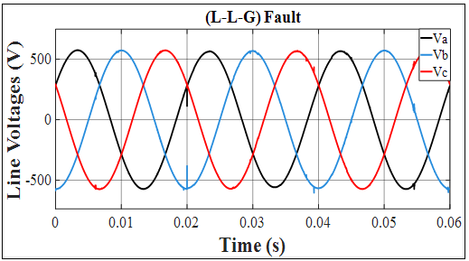
The voltage waveforms have been improved, and they become sinusoidal forms without any distortion after adding the SSFCL to the system, as shown in Figure 18.
Figure 18. Line voltages during (L-L-G) fault with SSFCL
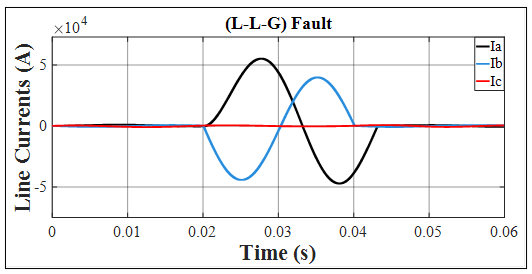
The line current has increased significantly to 55000A when the system is subjected to (L-L-G) fault in the absence of the SSFCL controller, as shown in Figure 19.
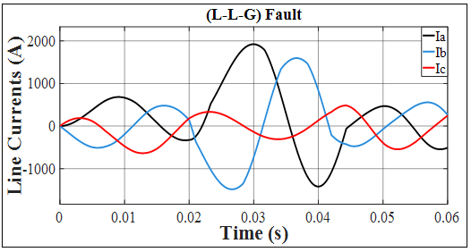
The current will decrease from 55000A to 1900A, with a reduction rate of 96.5%, with an error margin of 0.045% when the SSFCL is used, as shown in Figure 20. it can be seen that the fault current was reduced to accepted values.
Figure 19. Line currents during (L-L-G) fault without SSFCL
Figure 20. Line currents during (L-L-G) fault with SSFCL
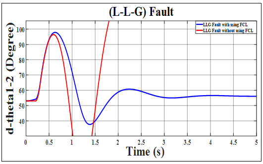
The influence of SSFCL operation on system stability by measuring the dθ1-2 of the synchronous generator when the system is subjected to (L-L-G) fault, as shown in Figure 21.
This figure shows that the system is unstable when it is subjected to a fault and in the event that the SSFCL is not used (the red curve), while the system works stably in the case of using SSFCL (the blue curve). The simulink results demonstrated the controller's effectiveness in stabilizing the system and maintaining normal operation.
Figure 21. Difference in rotor angles during (L-L-G) fault
4.4 Three lines to ground (3L-G) fault
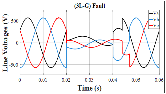
The line voltage waveforms when the system is subjected to (3L-G) fault are shown in Figure 22. From this figure, it can be seen the amount of drop, as well as the distortion in the line voltages as a result of this fault, and the system is working abnormally.
Figure 22. Line voltages during (3L-G) fault without SSFCL
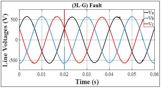
The voltage becomes sinusoidal form, and the distortion has been eliminated with SSFCL, as shown in Figure 23.
Figure 23. Line voltages during (3L-G) fault with SSFCL
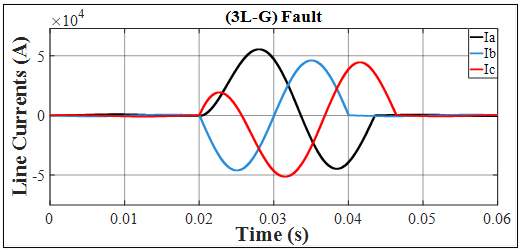
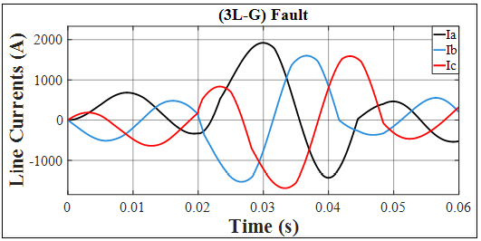
The line current has increased significantly, reaching 55000A when the system is subjected to (3L-G) fault in the absence of the SSFCL controller, as shown in Figure 24.
Figure 24. Line currents during (3L-G) fault without SSFCL
Figure 25. Line currents during (3L-G) fault with SSFCL
The current will decrease from 55000A to 1900A, with a reduction rate of 96.5%, with an error margin of 0.045% when the SSFCL is used, as shown in Figure 25.
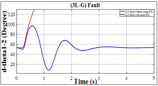
The system is unstable when it is subjected to a fault and in the case of the absence SSFCL (the red curve), while the system works stably in the case of using SSFCL (the blue curve), when the system is subjected to (3L-G) fault, as shown in Figure 26.
Figure 26. The difference in rotor angles during (3L-G) fault
This study investigates the effects of a Solid-State Fault Current Limiter (SSFCL) on the performance of power systems. The SSFCL provides flexibility, decreases costs, mitigates short circuit levels, and improves transient stability and system reliability. A simulation model of the SSFCL and its control system was developed and validated in conjunction with a power distribution system model for fault testing. The results indicate that the SSFCL identifies fault currents, engages its control circuit, and redirects the fault current to the limiting reactor. The SSFCL effectively decreases fault current, resulting in a 96% reduction in (L-G) faults, 96.7% in (L-L) faults, and 96.5% in (L-L-G) and (3L-G) faults. The SSFCL contributes to system rotor angle stability (transient stability) by influencing the rotor angle of the synchronous generator during the fault, where the results show great damping for rotor angle when SSFCL is used.
The authors express their gratitude for the substantial support and assistance the University of Mosul-College of Engineering provided during this work.
[1] Hamada, A.M., Ahmed, A.R., Hassan, S. (2022). A comprehensive review on superconducting and non-superconducting FCLs for power network. International Journal of Advances in Engineering and Management (IJAEM), 4(1): 1003-1017. https://doi.org/10.35629/5252-040110031017
[2] Moon, W.S., Won, J.N., Huh, J.S., Kim, J.C. (2013). A study on the application of a superconducting fault current limiter for energy storage protection in a power distribution system. IEEE Transactions on Applied Superconductivity, 23(3): 5603404-5603404. https://doi.org/10.1109/TASC.2013.2238594
[3] Shivakumar, M.R., Aradhya, R.S. (2018). Solid state fault current limiter (SSFCL) in power system-A case study. AIP Conference Proceedings, 2039(1): 020071. https://doi.org/10.1063/1.5079030
[4] Bălan, H., Neamț, L., Buzdugan, M.I., Varodi, T., Pop, E. (2016). Fault current limiter with solid-state circuit breakers. IOP Conference Series: Materials Science and Engineering, 144(1): 012001. https://doi.org/10.1088/1757-899X/144/1/012001
[5] Kosa, J. (2012). Novel 3-phase inductive fault current limiter. Physics Procedia, 36: 1258-1263. https://doi.org/10.1016/j.phpro.2012.06.286
[6] Gawusu, S. (2024). Impact of renewable energy integration on commodity markets. https://doi.org/10.2139/ssrn.4682719
[7] Alsammak, A.N.B., Al-Kaoaz, H.N.A. (2023). Design of a fuzzy distance relay taking into consideration the impact of using a unified power flow controller. Eastern-European Journal of Enterprise Technologies, 122(5): 6-19. https://doi.org/10.15587/1729-4061.2023.277343
[8] Al-Kaoaz, H.N.A., Alsammak, A.N.B. (2023). Utilizing hybrid renewable energy systems for enhancing transient stability in power grids: A comprehensive review. Journal Européen des Systèmes Automatisés, 56(4): 687-696. https://doi.org/10.18280/jesa.560418
[9] Al-Kaoaz, H.N.A., Alsammak, A.N.B. (2023). Performance enhancement of distance relay in presence of unified power flow controller. International Journal of Power Electronics and Drive Systems (IJPEDS), 14(3): 1577-1588. https://doi.org/10.11591/ijpeds.v14.i3.pp1577-1588
[10] Alhattab, A.S., Alsammak, A.N.B., Mohammed, H.A. (2023). An intelligent mitigation of disturbances in electrical power system using distribution static synchronous compensator. Indonesian Journal of Electrical Engineering and Computer Science, 30(2): 633-642. https://doi.org/10.11591/ijeecs.v30.i2.pp633-642
[11] Mohammed, H.A., Alsammak, A.N.B. (2023). An intelligent hybrid control system using ANFIS-optimization for scalar control of an induction motor. Journal Européen Des Systèmes Automatisés, 56(5): 857-862. https://doi.org/10.18280/jesa.560516
[12] Salleh, Z.M., Alsammak, A.N.B., Mohammed, H.A. (2024). Enhancing power system transient stability using static VAR compensator based on a fuzzy logic controller. Journal Européen des Systèmes Automatisés, 57(6): 1565-1572. https://doi.org/10.18280/jesa.570603
[13] Li, B., He, J., Li, Y., Li, R. (2018). A novel solid-state circuit breaker with self-adapt fault current limiting capability for LVDC distribution network. IEEE Transactions on Power Electronics, 34(4): 3516-3529. https://doi.org/10.1109/TPEL.2018.2850441
[14] Vobecký, J. (2015). The current status of power semiconductors. Facta Universitatis-Series: Electronics and Energetics, 28(2): 193-203. https://doi.org/10.2298/fuee1502193v
[15] Queiroz, A.T., Bitencourt, A. A., Nogueira, C.S., Martins, F.G., Fernando, J.M.D., Polasek, A., Sotelo, G.G. (2024). Development of a hybrid fault current limiter. IEEE Transactions on Applied Superconductivity, 34(3): 5601105. https://doi.org/10.1109/TASC.2024.3370124
[16] Thute, R.S., Bahirat, H.J., Khaparde, S.A. (2023). Impact of superconducting fault current limiter with delayed recovery on transient rotor angle stability. Electric Power Systems Research, 223: 109656. https://doi.org/10.1016/j.epsr.2023.109656
[17] Chandio, R.H., Shah, M.A., Memon, A.A., Ali, K.H., Soomro, J.B., Alamri, B., Althobaiti, A., Alqarni, M. (2025). Fault current handling in large-scale MMC-HVDC systems: An improved approach with DC circuit breaker and fault current limiter. Frontiers in Energy Research, 13: 1430142. https://doi.org/10.3389/fenrg.2025.1430142
[18] Yadav, S., Choudhary, G.K., Mandal, R.K. (2014). Review on fault current limiters. International Journal of Engineering Research & Technology (IJERT), 3(4): 1595-1603.
[19] Seyedi, H., Tabei, B. (2012). Appropriate placement of fault current limiting reactors in different HV substation arrangements. Circuits Syst., 3(3): 252-262. https://doi.org/10.4236/cs.2012.33035
[20] Leung, E.M. (2000). Superconducting fault current limiters. IEEE Power Engineering Review, 20(8): 15-18. https://doi.org/10.1109/39.857449
[21] Hartung, K.H., Schmidt, V. (2009). Limitation of short circuit current by an IS-limiter. In 2009 10th International Conference on Electrical Power Quality and Utilization, Lodz, Poland, pp. 1-4. https://doi.org/10.1109/EPQU.2009.5318861
[22] Ahmad, M., Wang, Z. (2019). A hybrid DC circuit breaker with fault-current-limiting capability for VSC-HVDC transmission system. Energies, 12(12): 2388. https://doi.org/10.3390/en12122388
[23] Endo, M., Hori, T., Koyama, T., Kaiho, K., Yamaguchi, I., Arai, K., Mizoguchi, H., Yanabu, S. (2009). Development of a superconducting fault current limiter using various high-speed circuit breakers. IET Electric Power Applications, 3(4): 363-370. https://doi.org/10.1049/iet-epa.2007.0499
[24] Esmaeili, Z., Heydari, H. (2025). A review of the effect of common fault current limiters (FCLs) on power systems reliability. The Journal of Engineering, 2025(1): e70057. https://doi.org/10.1049/tje2.70057
[25] Rocha Junior, E.B., Batista, O.E., Simonetti, D.S.L. (2022). Differential analysis of fault currents in a power distribution feeder using abc, αβ0, and dq0 reference frames. Energies, 15(2): 526. https://doi.org/10.3390/en15020526
[26] Valdes, M.E., Hansen, S., Sutherland, P. (2010). Optimizing circuit breaker instantaneous trip settings for selectivity and arc flash performance simultaneously. In 2010 IEEE IAS Electrical Safety Workshop, Memphis, TN, USA, pp. 112-118. https://doi.org/10.1109/ESW.2010.6164467