Abduljabbar O. Hanfesh![]()
© 2025 The author. This article is published by IIETA and is licensed under the CC BY 4.0 license (http://creativecommons.org/licenses/by/4.0/).
OPEN ACCESS
This research investigates the development and application of an adaptive speed control approach for a Hybrid Energy Storage System (HESS)-powered Field-Oriented Controlled (FOC) induction motor. The HESS offers a reliable and adequate power supply solution for water extraction applications by combining a photovoltaic (PV) system, a battery, and a supercapacitor. A single-ended primary-inductor converter (SEPIC) using the Perturb and Observe (P&O) Maximum Power Point Tracking (MPPT) method extracts the most power from the PV system. A PI controller controls the HESS, which consists of a battery and supercapacitor, to maximize energy efficiency and system stability. An adaptive PI speed controller regulates the FOC induction motor with a centrifugal pump to achieve exact speed and torque monitoring. The controller dynamically modifies its gains to adapt to changing operating conditions and guarantee peak performance and energy efficiency. The simulation results show the effectiveness of the suggested system. The FOC permits precise speed and torque control, the SEPIC converter sustains a steady output voltage, and the P&O MPPT algorithm effectively tracks the maximum power point. By increasing the system's reactivity and resilience, the adaptive PI speed controller raises the effectiveness of water extraction. This study advances water extraction technologies driven by renewable energy, fostering effective and sustainable water management.
adaptive speed control, FOC, induction motor, HES, PV system, MPPT, water extraction
There is not enough of renewable energy, and the technology are constantly evolving. Renewable energy may be used in a variety of ways. In our daily lives, the majority of us currently utilize renewable energy. One of the best solutions for renewable energy is Solar energy captured by photovoltaic (PV) devices. However, due solar energy is not continuous, efficient energy management system and storage devices are important to ensure an efficient use of the power [1, 2].
Batteries and supercapacitors are two types of energy storage technologies connected in HESS [3], and that might a practical solution to the problems brought on by fluctuating renewable energy sources. HESS can offer increasing of energy storage capacity, enchantment of power density, and longer cycle life by combining the advantages of several storage approaches [4].
Using a focus on water extraction applications utilizing centrifugal pumps, [5]. Improving utilization of energy, increasing system efficiency, and enhancing the overall effectiveness of the water extraction process are the aims of the suggested system [6].
A PV system with a SEPIC converter, and a P&O MPPT [7] algorithm is used to extract the most amazing power from solar panel. Voltage step-up and step-down operations are made possible by the SEPIC converter's flexible power conversion capabilities. The P&O MPPT algorithm dynamically adjusts the PV system's operating point to maximize producing electricity in the surface of variable solar irradiation [8].
The battery and supercapacitor that make up the HESS are connected by a bidirectional DC-DC converter. While the supercapacitor offers greater power density and quick charge-discharge capabilities, the battery maintains energy for a long time. A proportional-integral (PI) controller adjusts the power flow between the battery and supercapacitor to maximize energy efficiency and system stability [9]. The centrifugal pump is powered by a FOC induction motor. FOC is an advanced control method [10] that makes it possible to precisely regulate the motor torque and speed. In daily life, the majority of us currently utilizing renewable energy by modifying the stator flux and torque components independently, FOC enhances dynamic performance and efficiency. FOC based on conventional PID speed controllers have troubles like high overshoot try and error tuning, so it is necessary to convert to another type that adaptivity tuning parameters to handle different scenarios [11]. Under different levels of solar radiation, the adaptive speed controller maximizes the system's performance. By adjusting the reference speed of the induction motor based on the amount of solar power available, the controller maximizes water extraction and ensures cost-effective energy use. This paper examines the use of an adaptive speed controller for a field-oriented controller (FOC) induction motor powered by a HESS. A large number of simulations and tested and conducted in different operational contexts.
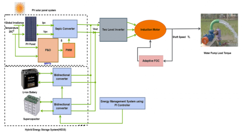
Figure 1 shows the configuration of the proposed solar PV based SEPIC converter fed induction motor for water pumping. The proposed system consists of a solar PV, SEPIC converter, hybrid storage system (battery and supercapacitor), induction motor, and centrifugal pump. Variable solar energy can be efficiently stored and used by integrating a HESS consisting of a battery and supercapacitor. By doing that, the water extraction system's total efficiency and energy losses are reduced. The HESS offers a backup power source to lessen the effects of intermittent solar radiation and grid power delays. That ensures a steady flow of water and improves the system's dependability. The novelty of using a supercapacitor with a battery is to protect the battery and prevent the sudden high load demand.
Figure 1. The proposed solar water pump system
3.1 PV panel
As the system's leading renewable energy source, PV panels are essential. Through the PV effect, these panels convert sunlight into electrical energy directly. Direct current (DC) power is produced by the solar cells in the panels, absorbing photons from sunlight and creating electron-hole pairs that move through the panel's circuitry [12].
Table 1. The specification of PV panels [13]
|
Parameter |
Value |
|
Parallel strings |
1 |
|
Series connected modules per string |
8 |
|
Maximum power |
235.024 W |
|
Cells per module |
60 |
|
Open circuit voltage |
36.8 V |
|
Short circuit current |
8.54 A |
|
Voltage at MPP |
29.6 V |
|
Current at MPP |
7.94 |
After that, a power electronic converter—a SEPIC converter—receives the generated DC power in the system. This converter effectively converts the DC power into an appropriate voltage level to charge the battery and supercapacitor in the HESS. Additionally, by continuously modifying the operating point to optimum power production under conditions of variable solar irradiation, the P&O MPPT algorithm improves the power extraction from the PV panels. The proposed technology promotes sustainable and eco-friendly energy practices by reducing dependency on traditional fossil fuel-based power sources by utilizing solar energy. The specification of PV panel is shown in Table 1 and the mathematical model of the PV panel is given in references [13, 14].
3.2 SEPIC converter
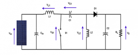
As a multipurpose DC-DC converter, the SEPIC is an essential part of the proposed system. It effectively converts the DC power produced by the PV panels into voltage level that is appropriate for HESS charging , the SEPIC converter shown in Figure 2, can step up and down voltage, which makes it perfect for a variety of applications, the SEPIC converter makes sure that the HESS gets the power it needs to maintain its ideal state of charge by carefully regulating the duty cycle of its switching components even in situation when solar irradiation varies this ensures a steady and effective energy flow throughout the system. The SEPIC converter mathematical model may be found in references [15, 16], and the specification of SEPIC shown in Table 2.
Figure 2. Equivalent of the SEPIC converter
Table 2. The specification of SEPIC converter
|
Parameter |
Value |
|
Cin |
100*10-6 |
|
C1 |
200*10-6 |
|
L1 |
3*10-3 |
|
L2 |
200*10-6 |
|
C2 |
750*10-5 |
The output voltage can be expressed as:
$V_o=V_s\left(\frac{D}{1-D}\right)$ (1)
The duty cycle can be found as follows:
$D=\frac{V_o}{V_o+V_s}$ (2)
As in the boost converter, so the output ripple voltage is
$\Delta V_0=\Delta V_{c 2}=\frac{V_o D}{R C_2 f}$ (3)
$C_2=\frac{D}{R\left(\frac{\Delta V_0}{V_0}\right) f}$ (4)
$C_1=\frac{D}{R\left(\frac{\Delta V_{C 1}}{V_0}\right) f}$ (5)
3.3 Battery
The HESS's battery is essential for storing extra energy. It is a dependable energy store, to insure that the induction motor will always have power, even when the sun isn't shining [17]. A bidirectional DC-DC converter attached to the battery enables both charging and draining. The mathematical model of the battery is given in studies [18, 19], and its specification shown in Table 3.
Table 3. The specification of battery [18]
|
Parameter |
Value |
|
Nominal voltage |
400 V |
|
Rated capacity |
14 Ah |
|
Initial state-of-charge |
50 % |
|
Battery response time |
108 |
|
Number of parallel capacitors |
0.1→S |
The I.M. and the system's peak power consumption, which occurs during times of high water demand or when the pump operates at high speeds at 400V, are the parameters that are used to size the battery and supercapacitor in the HESS. The supercapacitor and battery must be sized to meet these high power requirements.
3.4 Supercapacitor
The battery in the probosed HESS is supplemented by a high-performance energy storage device called a supercapacitor. Its specifications are shown in Table 4, and it offers excellent power density and fast charging and discharging capabilities. It works very efficiently under repeated charge and discharge cycles and short power peaks. Supercapacitors are well suited to reduce the effects of sudden changes in motor load or transient power fluctuations caused by solar radiation due to their rapid energy output and absorption capabilities [17]. In conjunction with the battery, the supercapacitor enhances the overall power output capability and dynamic behavior of the system. This ensures that the induction motor receives a stable, uninterrupted power supply, even under demanding operating conditions. Additionally, the supercapacitor increases the overall reliability and extends the lifetime of the system by reducing the load on the battery. The mathematical model of the supercapacitor is presented in the study [20].
Table 4. The specification of supercapacitor converter
|
Parameter |
Value |
|
Rated capacitance |
15.6 F |
|
Equivalent DC series resistance |
150*10-3 $\Omega$ |
|
Rated voltage |
403 V |
|
Number of series capacitors |
108 |
|
Number of parallel capacitors |
1 |
|
Initial Voltage |
390 V |
|
Operating temperature |
25℃ |
3.5 Bidirectional converter
Bidirectional converter, charge and discharge energy from energy Storage system devices which are battery and super capacitor at appropriate rate, to ensure optimum power flow and better system performance [21]. In other word, the bidirectional converter manages the power flow to the battery and super capacitor to maximize system efficiency and reliability buy controlling the current [22].
3.6 Induction motor
Our system's primary actuator is an induction motor, which powers the centrifugal pump by transforming electrical energy into mechanical energy. It is ideally suited for water extraction applications due to its sturdy design and capacity to function under challenging conditions [23].
FOC is used to precisely control the torque and speed of an induction motor. This sophisticated control method can independently control the torque and flux components of the motor [23, 24].
In order to enhance the water pump performance for water extraction and ensure the optimum use of energy, the FOC was used in this work to obtain a precise control the torque and speed of induction motor and good response for different conditions [25].
The motor parameters are given in Table 5.
Table 5. The parameters of motor
|
Parameter |
Value |
|
Stator Voltage |
Vs = 398/690 V |
|
Stator Frequency |
50 Hz |
|
Stator Resistance |
4.85 $\Omega$ |
|
Stator Inductance |
0.274 H |
|
Rotor Resistance |
3.805 $\Omega$ |
|
Rotor Inductance |
0.274 H |
|
Mutual Inductance |
0.258 H |
|
No. of Pair of Poles |
2 |
3.7 Water pump
For abroad rang of uses, pumps are available in different sizes, based on their fundamental working principle, they can categorize as either dynamic or displacement pumps, centrifugal and special effect pumps are two subcategories of dynamic pumps. Pumps for displacement can be divided into reciprocating or rotary pumps [25].
An induction motors torque and speed may be accurately controlled via FOC.
By adjusting the speed of the motor according to the available solar energy, the adaptive speed controller further improves the performance of the pump and ensures efficient water extraction even in different environmental conditions [26].
In this work a center fugal pumps are used, and load torque equations come first:
$T_{\text {pump }}=K_T \Omega^2$ (6)
where, KT represents the constants of the pump.
The second is the amount of hydraulic power needed to transport water.
$P_h=g H Q_\rho$ (7)
where,
g: The pump's power transmission to the fluid W(watt);
H: is the total height (m);
Q: is the flow (m3/s);
P: is the density of water (1000 kg/m3).
We employed the following similarity equations to implement the model:
$H=H_m\left(\frac{N}{N_m}\right)^2$ (8)
$Q(t)=Q_m\left(\frac{N}{N_m}\right)$ (9)
where,
Hm: is the maximum height (m);
N: is the instantaneous speed (rpm);
Nm: is the maximum speed (rpm);
Q: is the instantaneous flow (m3/s);
Qm: is the maximum flow (m3/s).
4.1 P&O
The P&O MPPT algorithm is popular for maximizing the PV system's power output. It works by repeatedly altering the operating voltage of the PV system and tracking the change in power output that results. The algorithm modifies the SEPIC converter's duty cycle to raise or lower the voltage depending on whether the power output rises or falls. This process continues until the maximum power point (MPP), where the power output is maximized, is attained.
The P&O algorithm uses little processing power and is comparatively easy to implement.
However, it might fluctuate around the MPP, mainly when solar irradiance changes rapidly. The P&O algorithm has been improved and modified to lessen these oscillations, including predictive control tactics and adaptive step size techniques.
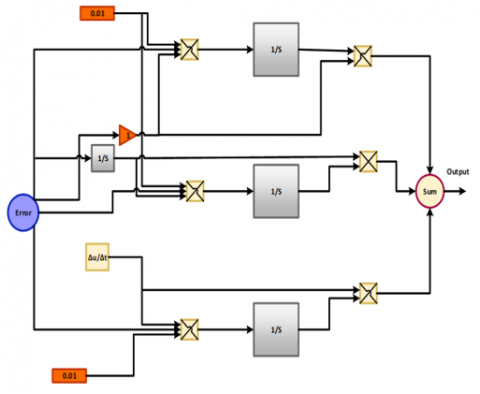
4.2 Adaptive PID controller
The induction motor's speed is precisely and reliably controlled using an adaptive PID speed controller. The PID controller effectively corrects errors and rejects disturbances with proportional and integral terms as shown in Figure 3.
Figure 3. An adaptive PI controller
However, a fixed-gain PID controller's performance may deteriorate under different operating situations, such as variations in load or motor specifications [27].
To overcome this constraint, the PID controller incorporates an adaptive mechanism. This approach modifies the controller's gains (Kp and Ki) in real-time while continuously monitoring the system's behaviour. The primary objective is to ensure that the motor speed precisely matches the intended reference speed, which can be dynamically changed in response to the water demand and solar power availability. The adaptive PID controller precisely controls the motor torque to satisfy the centrifugal pump's fluctuating load demands. That involves making sure that load changes, acceleration, and deceleration are all done smoothly. The adaptive PID improves energy efficiency by reducing energy losses and maximizing the motor's operating point. During transients, this involves reducing overshoot and settling time. The controller sustains peak performance by adjusting to shifting circumstances, leading to better transient responsiveness, lower steady-state error, and increased robustness [28].
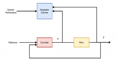
Adaptive control represents a cutting-edge field within control system design, specifically tackling the challenges posed by uncertainties in system models (as illustrated in Figure 4). Unlike conventional linear controllers, adaptive controllers can modify their behavior independently to handle these uncertainties efficiently. Adaptive control techniques fall into two categories: direct and indirect. The estimation of plant parameters is given priority in indirect approaches, which then use the inferred model knowledge to modify the controller's behavior. On the other hand, direct approaches use the assumed parameters directly within the structure of the adaptive controller [27].
Figure 4. Structure of adaptive control
The overall performance of the induction motor drive system is greatly improved by adding an adaptive PID speed controller, which results in increased energy economy and accurate control of the water extraction process.
$P I(s)=k_p\left(1+\frac{1}{T_i s}\right)$ (10)
4.3 Field-oriented control
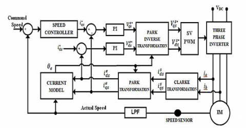
Field-Oriented Control (FOC) shown in Figure 5 is a sophisticated control technique that enables precise control of the induction motor's speed and torque. In the probosed system, we employ an adaptive PI speed controller in conjunction with a decoupling method to further enhance the performance of the FOC drive [29].
Figure 5. FOC of induction motor
By successfully separating the control of the stator current components, the decoupling approach makes it possible to control the torque and flux components independently. Improved dynamic response and precise tracking of the intended reference values result from this decoupling, ensuring that modifications to one component don't negatively impact the other [30].
To maximize performance under various operating situations, the adaptive PI speed controller continuously assesses the system's behaviour and modifies its gains. The controller can adjust for variations in load, motor characteristics, and ambient conditions because of its adaptive nature. By dynamically changing the controller's gains, the system can achieve improved resilience, fewer steady-state errors, and faster response times [31].
A high-performance induction motor drive system ideal for water extraction applications is produced by combining FOC, decoupling, and adaptive PI control. This method controls the motor's speed and torque, resulting in effective water pumping and optimal energy use [32].
In our case, we direct the flux with the d-axis, which implies
$\phi_{q r}=0$ and $\phi_r=\phi_{d r}$ (11)
The following equations are obtained after the orientation of the flux, and the rotor flux is controlled by acting on the current Ids, while the torque can be controlled with the stator current Iqs:
$V_{d s}=\sigma L_s \frac{d i_{d s}}{d t}+R_s i_{d s}-\sigma L_s \omega_s i_{q s}+\frac{L_m}{L_r} \frac{d \phi_r}{d t}$ (12)
$V_{d s}=\sigma L_s \frac{d i_{q s}}{d t}+R_s i_{q s}-\sigma L_s \omega_s i_{d s}+\frac{L_m}{L_r} \omega_s \phi_r$ (13)
The following are the phrases for the pair and flux:
$T_e=\frac{3 P L_m}{2 L_r}\left(\phi_{d r} I_{q s}\right)$ (14)
$\phi_{d r}=L_m I_{d s}$ (15)
The following represents the rotor pulsation:
$\omega_r=\frac{L_m I_{q s}}{B_r \varphi_{r d}}=\omega_s-p \Omega$ (16)
where, $\sigma=1-\frac{L_m^2}{L_s * L_r}$ and $B_r=\frac{L_r}{R_r}$.
4.4 Energy management system
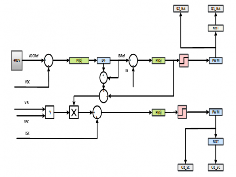
The PI controller is essential in controlling the energy flow within the HESS to ensure that the stored energy is used as efficiently as possible. The PI controller determines the appropriate power distribution between the two storage devices by monitoring the battery and supercapacitor's state of charge (SOC). The supercapacitor delivers quick power bursts to satisfy peak demand, guaranteeing that the battery is not subjected to undue stress [11].
Together, the integral and proportional terms of the PI controller control the power flow. While the integral term removes steady-state faults, the proportional term responds quickly to SOC problems. The HESS can function effectively and dependably by controlling the energy flow by carefully tuning the PI controller's gains.
The PI controller shown in Figure 6 can also be used with more sophisticated control methods like fuzzy logic or model predictive control to improve the energy management plan further. Under different operating situations, such as fluctuating solar irradiation and load demands, these strategies can aid in optimizing the system's performance.
Figure 6. Energy management system featuring a PI controller integrated with a HESS
5.1 First scenario results
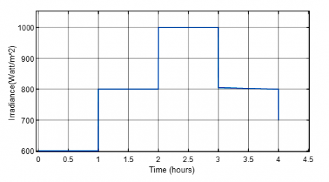
Figure 7 shows how the global irradiance changed over around 4.5 hours. The intensity of solar radiation incident on a horizontal surface is known as the irradiance, expressed in watts per square meter (W/m²).
Figure 7. The global irradiance profile
The graph displays a clear diurnal pattern with distinct peaks and valleys. At first, the irradiance is still relatively low, at about 600 W/m2, suggesting that it is either early in the morning or late at night. Between approximately 1 and 2 hours, the irradiance experiences a significant increase, reaching a peak of around 1000 W/m². This sudden increase coincides with when the sun is at its strongest, probably midday. The irradiance steadily decreases after the peak, reaching a value of about 800 W/m² after about three hours. This decline represents the slow waning of solar intensity as the day continues into the afternoon.
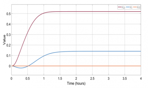
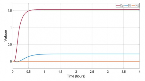
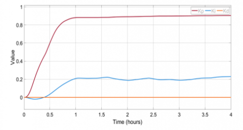
The graph shows a typical solar irradiance profile, with a rise in the morning, a peak in the middle of the day, and a fall in the afternoon. Numerous applications, including forecasting, agricultural planning, and solar energy system design, can benefit from this information. The adaptive PID controller response is shown in Figure 8. In this scenario, the adaptive PID controller continually tunes its gains (kp and ki) to maximize system performance. The controller uses a self-tuning algorithm to predict the system characteristics and appropriately tune gains. The system shows few fluctuations; therefore, the derivative gain (Kd) is minimal. Figure 9 shows the FOC performance of tracking speed and torque.
Figure 8. Adaptive PID controller response
(a)
(b)
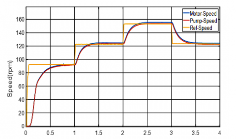
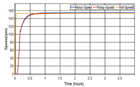
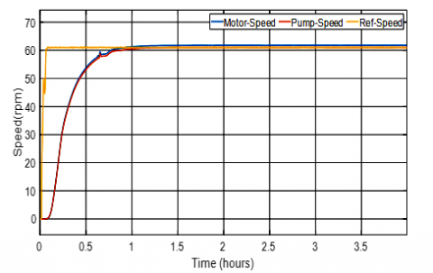
Figure 9. The system response of (a) speed response, (b) torque response
The given graph demonstrating the adaptive FOC system's dynamic response for speed tracking in the first situation is displayed in Figure 9(a). The graph shows how three important speed variables have changed throughout time:
Reference speed (yellow): This is the intended or target speed the system tries to reach. It acts as the controller's reference input.
Motor speed (Blue): This displays the induction motor's actual rotational speed, directly connected to the centrifugal pump.
Pump speed (Red): This represents the water pump's speed, which is directly influenced by the motor speed.
The graph reveals that the system exhibits excellent dynamic performance. When the reference speed changes, the motor and pump speed quickly respond and track the reference accurately. The transient response is characterized by minimal overshoot and settling time, indicating effective control and minimal energy losses.
The motor and pump speeds are closely aligned, indicating an excellent mechanical coupling and little mechanical losses between the two parts. This is essential for effective water extraction and optimal energy transfer.
The graph shows how well the adaptive FOC system achieves accurate and responsive speed control, allowing for dependable and effective water extraction operations.
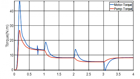
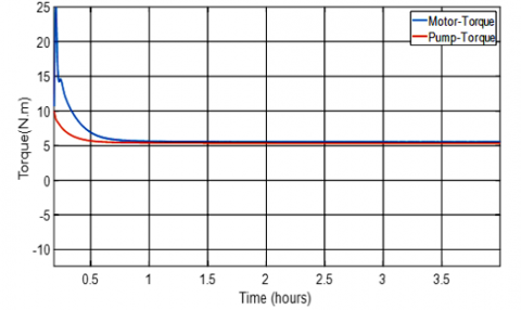
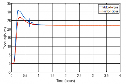
In the first scenario it is clear the adaptive FOC system dynamic reaction for torque tracking is shown in Figure 9(b). The graph shows the time evaluation of two main torque variables.
The torque required by the water and overcome the load is known as the pump torque (Red).
Motor torque (Blue): This displays the torque the pump drives from the induction motor.
The graph illustrates efficient power transmission and excellent management indicating that the motor torque closely tracks the pump torque with just a little overshoot or setting period. This shows that the adaptive FOC controller can swiftly modify the motor's torque output to meet the water pump's changing needs.
The startup transient, during which the motor accelerates to its operational speed, is represented by the first peak in both the motor and pump torque. The torque stabilizes constantly when the motor approaches a steady state. The motor torque is quickly adjusted to accommodate any subsequent changes in the load torque, such as water flow or pressure variations.
Overall, the graph demonstrates the effectiveness of the adaptive FOC system in achieving precise and responsive torque tracking, ensuring efficient and reliable operation of the water extraction system.
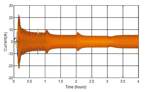
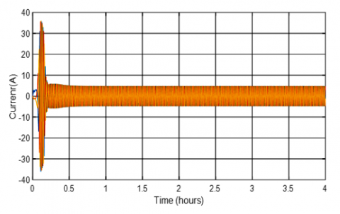
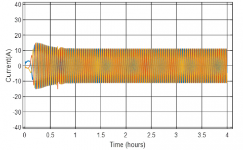
Figure 10. Stator current waveforms of the induction motor
Figure 10 shows the time variation of the induction motor's three-phase stator currents (Ia, Ib, Ic). These currents generate the rotating magnetic field that drives the motor's rotor.
The graph demonstrates that the currents have a sinusoidal waveform, typical of balanced three-phase systems. The roughly 120-degree phase difference between the three currents guarantees the creation of a rotating magnetic field. As the load and speed of the motor fluctuate over time, so does the amplitude of the currents.
The motor's startup phase is represented by the first transient period, characterized by oscillations of greater amplitude. The current waveforms stabilize into a more consistent pattern as the motor enters steady-state operation. The motor's load and the applied voltage determine the steady-state current values.
The graph shows that the induction motor is operating correctly and that the control technique successfully produces seamless and effective operation. Good quality power and low power losses are indicated by the sinusoidal form of the currents and the lack of noticeable harmonics.
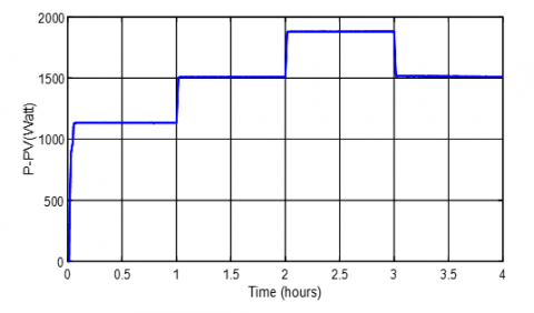
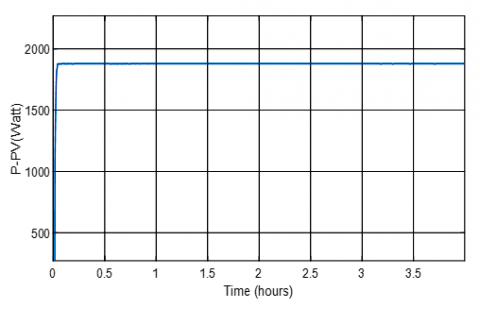
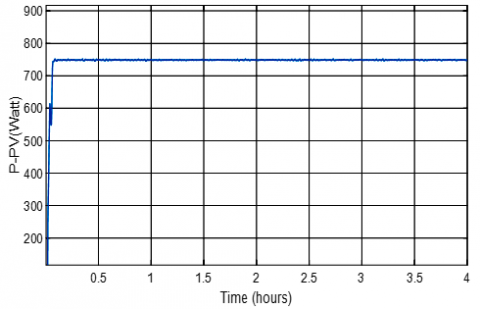
The power output of the PV system under various sun irradiation conditions is shown in Figure 11. Plotting the power output against time offers information on the efficiency of the MPPT algorithm and the system's operation.
Figure 11. Power output of the PV system
As the intensity of the solar irradiation increases, the power output progressively rises from zero. This initial rise occurs in the early morning when the sun shines on the PV panels.
The power output stabilizes at a maximum value of roughly 2000 W/m² once the sun irradiation peaks. This shows that the MPPT algorithm efficiently collects the maximum power from the PV system and tracks the maximum power point (MPP).
The power output fluctuates during solar irradiance, such as sunrise, sunset, or cloud cover. The MPPT algorithm swiftly modifies the PV system's operating point to minimise power losses to follow the moving MPP.
The power output curve's general form roughly resembles the profile of solar irradiation. Power output rises in tandem with increased solar irradiation, and vice versa. This illustrates how well the PV system captures solar energy and transforms it into electrical power.
The PV system with the P&O MPPT algorithm can effectively track the MPP and provide the highest power output under a range of solar irradiation circumstances, as seen in the image below. This guarantees the best possible use of solar energy and enhances the HESS-based water extraction system's overall functionality.
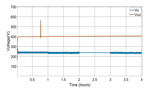
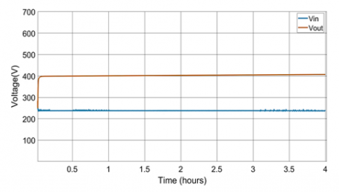
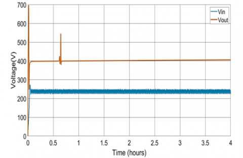
Despite variations in the input voltage from the PV panel, Figure12 illustrates how well the SEPIC converter controls the output voltage at a steady 400V.
Input Voltage (Vin): Significant fluctuations in the input voltage are probably caused by temperature changes and solar irradiation. The blue curve's fluctuations show these changes.
Output Voltage (Vout): The output voltage (brown curve) stays astonishingly constant throughout the observation time at 400V. This illustrates how well the SEPIC converter keeps the output voltage steady even when the input conditions change.
When the input voltage increases during the first phase, the SEPIC converter swiftly modifies its duty cycle to control the output voltage to the appropriate level. A seamless transition to the steady-state condition is ensured by this quick reaction, which reduces overshoot and undershoot.
The SEPIC converter keeps the output voltage at 400V with little ripple when the input voltage stabilizes. This demonstrates the converter's accuracy and effectiveness. The performance and efficiency of the entire system depend on the converter's capacity to manage changing input conditions while maintaining a steady output voltage.
Figure 12. SEPIC converter input and output voltage
5.2 Second scenario results
The adaptive FOC system's dynamic response for speed tracking in high irradiation settings (1000 W/m2) is shown in Figure13. It shows how three important speed variables change over time.
Figure 13. Adaptive PID controller response
Reference speed (Yellow): This is the intended or target speed the system tries to reach.
Motor speed (Blue): This displays the induction motor's rotational speed.
Pump speed (Red): This represents the water pump's speed.
The reference speed is much higher in this scenario than in the low irradiance scenario, which indicates the PV system's enhanced power availability. In reaction to the step change in the reference speed, the system responds quickly. The pump and motor speeds rapidly increase to get to the ideal operating point. Minimal overshoot from the system indicates accurate management and effective energy use. The motor and pump speeds closely follow the reference speed after the system reaches a steady state, guaranteeing precise and reliable operation.
The synchronization of the pump and motor speeds suggests minimum power losses and efficient mechanical linkage between the two parts.
The graphic below shows how well the adaptive FOC system tracks fast references in high-irradiance environments. Effective water extraction and the best possible use of solar energy are guaranteed by the system's quick reaction, slight overshoot, and precise steady-state tracking. The adaptive PID controller response is shown in Figure 13.
The time-domain response of the pump and motor speed and torque is shown in Figure 14 respectively. The motor and pump torque show a notable transient reaction at first, with a peak value followed by a decline. This fleeting action is standard when the motor is just starting up. The motor and pump torque levels are comparatively constant as the motor reaches a steady state. The motor torque is somewhat more significant than the pump torque to compensate for losses in the mechanical transmission system. The motor and pump torque waveforms exhibit a slight amount of torque ripple. Variations in motor parameters, suboptimal power electronics switching, and load fluctuations are some of the causes of this ripple.
To ensure optimal performance and efficient power transfer, the motor torque efficiently tracks the load torque needed by the pump.
(a)
(b)
Figure 14. I.M response of (a)speed and (b) torque response in the second scenario
The PV system's power output at high irradiance circumstances (1000 W/m2) is shown in Figure 15.
When solar irradiation increases, the PV system responds quickly. The power output rapidly increases to a maximum, demonstrating effective MPP tracking.
Figure 15. P&O MPPT response for high irradiance scenario
The power output stays constant at the highest value when the system enters a steady state, indicating how well the MPPT algorithm maintains ideal operating conditions.
The P&O MPPT algorithm performs exceptionally well in maximizing power extraction from the PV system in high irradiation situations, as shown in Figure 16. This enhances the HESS-based water extraction system's overall efficacy and efficiency.
Figure 16. SEPIC converter performance for high irradiance scenario
Figure 17. SEPIC converter performance for high irradiance scenario
Figure17 displays the tim domain waveforms of stator currents (Ia,Ib,Ic) of induction motor under conditions of powerful irradiation.
Each phase current is sinusoidal and 120 degrees out of phase with the others, giving the waveforms a balanced three-phase pattern. This is necessary for motors to operate smoothly and effectively.
Even if the waveforms have a sinusoidal general shape, there is still some harmonic distortion. Nonlinear magnetic effects, saturation, and switching losses in the power electronics converters are some of the causes of this distortion.
5.3 Third scenario results
Figure 18 shows the adaptive PID controller response. In contrast to the first scenario, the Ki value exhibits different behavior. It rises initially, then fluctuates slightly before leveling off at a constant value. It’s a rhythmic activity in Ki may suggest that low irradiance conditions cause more disruptions or fluctuations in the system. The controller modifies the integral gain to account for these disruptions and preserve precise control.
Figure 18. Adaptive PID controller response
The system response for the third case (400 w/m2) is displayed in Figure 19. Even with less power available, and the adaptive FOC controller can track the intended speed and torque references. This guarantees the induction motor and pumps run efficiently. The P&O MPPT algorithm can still track the maximum power point even with less solar irradiation. This ensures that the PV system will extract energy as efficiently as possible. Despite the PV panels' reduced input power, the SEPIC converter consistently maintains an output voltage of 400V. This illustrates its capacity to manage fluctuating input circumstances and offer the system a dependable power source.
The induction motor is functioning, smoothly and efficiently as evidenced by the waveforms of stator currents.
(a)
(b)
(c)
(d)
(e)
Figure 19. The system response of the third scenario is (a) speed tracking, (b) torque tracking, (c) P&O performance, (d) SEPIC converter, and (e) Iabc of induction motor
This study aims to reinforce the water pump performance driven by induction motor controlled using field-oriented technique. The system used a sustainable PV power source which used through a battery and super capacitor with the help P&O algorithm and SEPIC converter to get a stable and uninterrupted power supply voltage.
The results proved the efficiency of the proposed system to obtain a constant voltage with different conditions through the Techniques used for the PV energy system.
The integration of water pump speed control techniques which used in present work is a promising approach to enhance water management.
[1] Paris, B., Vandorou, F., Balafoutis, A.T., Vaiopoulos, K., Kyriakarakos, G., Manolakos, D., Papadakis, G. (2022). Energy use in greenhouses in the EU: A review recommending energy efficiency measures and renewable energy sources adoption. Applied Sciences, 12(10): 5150. https://doi.org/10.3390/app12105150
[2] Lee, C.G., Cho, L.H., Kim, S.J., Park, S.Y., Kim, D.H. (2021). Comparative analysis of combined heating systems involving the use of renewable energy for greenhouse heating. Energies, 14(20): 6603. https://doi.org/10.3390/en14206603
[3] Zuo, W., Li, R., Zhou, C., Li, Y., Xia, J., Liu, J. (2017). Battery-supercapacitor hybrid devices: Recent progress and future prospects. Advanced Science, 4(7): 1600539. https://doi.org/10.1002/advs.201600539
[4] McGeough, J.A., McCarthy, W.J. (2023). Encyclopedia Britannica. Machine Tool. https://www.britannica.com/technology/machine-tool.
[5] Devanshu, A., Singh, M., Kumar, N. (2019). An improved nonlinear flux observer based sensorless FOC IM drive with adaptive predictive current control. IEEE Transactions on Power Electronics, 35(1): 652-666. https://doi.org/10.1109/TPEL.2019.2912265
[6] Abed, M.A.N., Altahir, A.A.R., Abdulhadi, A. (2024). A review of hybrid electric vehicle configurations: Advances and challenges. Kerbala Journal for Engineering Sciences, 4(3): 259-282.
[7] Bhos, C., Nasikkar, P. (2024). Mitigation of power losses in solar photovoltaic systems under partial shading using optimization-based MPPT. Journal Européen des Systèmes Automatisés, 57(6): 1621-1630. https://doi.org/10.18280/jesa.570609
[8] Hanfesh, A.J.O., Mohammed, J., Salman, I., Mohammed, H., Ali, M. (2024). Design and implementation of a solar tracking system using a hydraulic system. AIP Conference Proceedings, 3002(1): 050001. https://doi.org/10.1063/5.0205799
[9] Habib, H.U.R., Waqar, A., Junejo, A.K., Elmorshedy, M.F., et al. (2021). Optimal planning and EMS design of PV based standalone rural microgrids. IEEE Access, 9: 32908-32930. https://doi.org/10.1109/ACCESS.2021.3060031
[10] Shary, D.K., Nekad, H.J. (2024). Position and speed control for permanent magnet DC motor based on different optimization algorithms. Journal Européen des Systèmes Automatisés, 57(6): 1705-1711. https://doi.org/10.18280/jesa.570618
[11] Sharma, A., Parakh, A. (2018). Design of solar powered induction motor drive for pumping application. International Journal of Latest Trends in Engineering and Technology, 10(1): 228-237. http://doi.org/10.21172/1.101.41
[12] Ma, T., Zhao, J., Li, Z. (2018). Mathematical modelling and sensitivity analysis of solar photovoltaic panel integrated with phase change material. Applied Energy, 228: 1147-1158. https://doi.org/10.1016/j.apenergy.2018.06.145
[13] Kadeval, H.N., Patel, V.K. (2021). Mathematical modelling for solar cell, panel and array for photovoltaic system. Journal of Applied and Natural Science, 13(3): 937-943. https://doi.org/10.31018/jans.v13i3.2529
[14] Surya, S., Arjun, M.N. (2021). Mathematical modeling of power electronic converters. SN Computer Science, 2(4): 267. https://doi.org/10.1007/s42979-021-00637-1
[15] Ali, M.O., Ahmad, A.H. (2020). Design, modelling and simulation of controlled Sepic DC-DC converter-based genetic algorithm. International Journal of Power Electronics and Drive Systems, 11(4): 2116-2125. https://doi.org/10.11591/ijpeds.v11.i4.pp2116-2125
[16] Cabrane, Z., Kim, J., Yoo, K., Ouassaid, M. (2021). HESS-based photovoltaic / batteries / supercapacitors: Energy management strategy and DC bus voltage stabilization. Solar Energy, 216: 551-563. https://doi.org/10.1016/j.solener.2021.01.048
[17] Hasib, S.A., Islam, S., Chakrabortty, R.K., Ryan, M.J., et al. (2021). A comprehensive review of available battery datasets, RUL prediction approaches, and advanced battery management. IEEE Access, 9: 86166-86193. https://doi.org/10.1109/ACCESS.2021.3089032
[18] Tamilselvi, S., Gunasundari, S., Karuppiah, N., Razak RK, A., et al. (2021). A review on battery modelling techniques. Sustainability, 13(18): 10042. https://doi.org/10.3390/su131810042
[19] Jing, W., Lai, C.H., Wong, W.S., Wong, M.D. (2018). A comprehensive study of battery-supercapacitor hybrid energy storage system for standalone PV power system in rural electrification. Applied Energy, 224: 340-356. https://doi.org/10.1016/j.apenergy.2018.04.106
[20] Argyrou, M.C., Christodoulides, P., Marouchos, C.C., Kalogirou, S.A. (2018). Hybrid battery-supercapacitor mathematical modeling for PV application using Matlab/Simulink. In 2018 53rd International Universities Power Engineering Conference (UPEC), Glasgow, UK, pp. 1-6. https://doi.org/10.1109/UPEC.2018.8541933
[21] Wang, B., Zhang, X., Manandhar, U., Gooi, H.B., Liu, Y., Tan, X. (2019). Bidirectional three-level cascaded converter with deadbeat control for HESS in solar-assisted electric vehicles. IEEE Transactions on Transportation Electrification, 5(4): 1190-1201. https://doi.org/10.1109/TTE.2019.2939927
[22] Jadhav, S., Devdas, N., Nisar, S., Bajpai, V. (2018). Bidirectional DC-DC converter in solar PV system for battery charging application. In 2018 International Conference on Smart City and Emerging Technology (ICSCET), Mumbai, India, pp. 1-4. https://doi.org/10.1109/ICSCET.2018.8537391
[23] Mehala, N., Dahiya, R. (2007). Motor current signature analysis and its applications in induction motor fault diagnosis. International Journal of Systems Applications, Engineering & Development, 2(1): 29-35.
[24] Venu Gopal, B.T., Shivakumar, E.G. (2020). A comparative performance analysis of indirect vector controlled induction motor drive using optimized ai techniques. Journal of Computational and Theoretical Nanoscience, 17(1): 464-472. https://doi.org/10.1166/jctn.2020.8692
[25] El Ouanjli, N., Derouich, A., El Ghzizal, A., Motahhir, S., Chebabhi, A., El Mourabit, Y., Taoussi, M. (2019). Modern improvement techniques of direct torque control for induction motor drives-a review. Protection and Control of Modern Power Systems, 4(2): 1-12. https://doi.org/10.1186/s41601-019-0125-5
[26] Uma, D., Vijayarekha, K. (2017). Modeling and simulation of VSI fed induction motor drive in Matlab/Simulink. International Journal of Electrical and Computer Engineering, 7(2): 584-595. https://doi.org/10.11591/ijece.v7i2.pp584-595
[27] Arun, S.V., Subramaniam, U., Padmanaban, S., Bhaskar, M.S., Almakhles, D. (2019). Investigation for performances comparison PI, adaptive PI, fuzzy speed control induction motor for centrifugal pumping application. In 2019 IEEE 13th International Conference on Compatibility, Power Electronics and Power Engineering (CPE-POWERENG), Sonderborg, Denmark, pp. 1-6. https://doi.org/10.1109/CPE.2019.8862351
[28] Verma, S., Mishra, S., Chowdhury, S., Gaur, A., Mohapatra, S., Soni, A., Verma, P. (2021). Solar PV powered water pumping system–A review. Materials Today: Proceedings, 46: 5601-5606. https://doi.org/10.1016/j.matpr.2020.09.434
[29] Zaparoli, I.O., Júnior, A.A., Êvo, M.T.A., Souza, D.S., De Paula, H. (2024). Early fault detection in FOC driven induction motors: A case study. IEEE Access, 12: 177919-177929. https://doi.org/10.1109/ACCESS.2024.3507756
[30] Zhao, B.Y., Zhao, Z.G., Li, Y., Wang, R.Z., Taylor, R.A. (2019). An adaptive PID control method to improve the power tracking performance of solar photovoltaic air-conditioning systems. Renewable and Sustainable Energy Reviews, 113: 109250. https://doi.org/10.1016/j.rser.2019.109250
[31] Shanan, D.S., Kadhim, S.K. (2023). Comparative analysis of airflow regulation in ventilator systems using various control strategies. Journal Européen des Systèmes Automatisés, 56(5): 811-821. https://doi.org/10.18280/jesa.560512
[32] Li, W., Xu, Z., Zhang, Y. (2019). Induction motor control system based on FOC algorithm. In 2019 IEEE 8th Joint International Information Technology and Artificial Intelligence Conference (ITAIC), Chongqing, China, pp. 1544-1548. https://doi.org/10.1109/ITAIC.2019.8785597