Ahmed G. Abdullah*![]() | Mohammed A. Ibrahim
| Mohammed A. Ibrahim![]() | Ali S. Saleh
| Ali S. Saleh![]()
© 2024 The authors. This article is published by IIETA and is licensed under the CC BY 4.0 license (http://creativecommons.org/licenses/by/4.0/).
OPEN ACCESS
This paper employs artificial neural networks (ANNs) in estimating and controlling the speed of a separately excited DC motor, which is also one of the most essential modern techniques used in control applications and to enhance the effectiveness of separately excited DC motor speed control. For speed control of a separately excited DC motor, the paper compares the performance of the conventional proportional integral (PI) and artificial neural networks (ANNs). A neural network (NNs) based controller is an extremely appreciated technology for accomplishing high-recital speed control. The simulation results are expose to demonstrate the efficacy and advantage of the control system of a separately excited DC motor (SEDCM) using ANNs over the traditional control arrangement. The integration of (ANNs) has shown significant improvements in performance in speed control of DC motors separately excited, chiefly in dynamic response and robustness in contradiction of load variations. This technique leverages the adaptive competences of ANNs to improve traditional control methods. In this manuscript, two controller for speed control of SEDCM are designed and simulated using matlab Simulink program. The first one is the PI controller and the second is the ANN controller, the results of the ANN controller based speed control of the SEDCM give quick response, low overshot, small settling time, zero steady state error when sudden change happened in reference speed or load torque. In addition, as compared with the results of PI controller which give slow response, high overshot, large settling time under the same conditions.
separately excited DC motor, speed control, simulation and modelling, PI controller, ANN
Precision and high-performance motor drives are essential in industrial settings, especially for controlling loads and monitoring speed limits [1]. Because of its simple and continuous control characteristics, the direct current DC motors have been widely used in many applications [2, 3], such as steel rolling mills, electric crank, electric vehicles, and robotic manipulators. When the DC motor is used, the first thing to think about is how to control the motor speed. In last decades, the proportional Integral (PI) controller has been used to control the speed of DC motor [4]. The major advantage of using traditional PI controller are its ability to make speed of motor is stable at step change in load or reference speed, but the disadvantage of using this controller, is slow response, a large peak overshot, large settling time, when sudden change in load or reference speed is happened [5]. PI controllers make up over ninety percent of controllers used in process control in industrial applications because of their versatility, simplicity, clear functionality, and ease of use [6]. However, conventional controllers like PI-perform badly in every situation, including ones involving disturbances, parameter variation, and load fluctuations. Moreover, it is still difficult to determine and modify the PI settings, and it takes a lot of work to get a satisfactory system response. Many methodology are used to design the values of Kp proportional constant and Ki integral constant of PI controller such that root-locus method, Ziegler-Nichols method, frequency response method [7]. Resulting from that, many researchers move towards using the intelligent control techniques, aiming to improve the performance of the DC motor speed control [8]. The most prominent intelligent techniques used are the artificial neural network ANN and fuzzy logic controller FLC techniques. The ANN and FLC control technique are presented as a great tool for controlling the systems where traditional control methods may fall, due to ability to deal with non-linear systems, as well as quick response. Strong learning capabilities for a variety of information are provided by this method, which resembles the neural network of the human brain [9].
In the past ten years, ANNs have gained a lot of attention due to their widespread applications in modeling, identity verification, testing, and control [10]. Given their precise speed control, direct current motor drives are the ideal choice for achieving accurate and high-performing motor drives in industrial applications [11]. In this paper a two controller for speed control of separately exited DC motor (SEDCM) are presented, designed and compared, the first one is PI controller based speed control of SEDCM and the second is ANN controller based speed control of SEDCM. The PI controller is designed using PID matlab tuner box while the ANN with back-propagation algorithms is designed and trained using thousands of example pattern obtained from variable load and reference speed condition. The two controller based speed control of SEDCM are simulated using Matlab Simulink. The results show that the ANN based speed control of SEDCM give a quick response, very low peak overshot, very small settling time, zero steady state error under sudden change in load torque or reference speed. As compared with PI based speed control of SEDCM which give slow response, large peak overshot, very large settling time, zero steady state error under sudden change in load torque or reference speed.
Nagarajan et al. [12] used a MATLAB/SIMULINK model and a closed-loop model using the chopper and proportional-integral controllers to control the speed of a DC motor. When switching losses were eliminated, motor efficiency rose to 95%.
Azman et al. [13] compared two artificially intelligent controllers for controlling a DC motor's speed: ANN and fuzzy logic control FLC. FLC is still effective at controlling the speed to match the reference speed of the controller, but the ANN controller responds more quickly and settles down sooner.
Hamoodi et al. [14] demonstrated in their research that ANN control responds more quickly than PID control to unforeseen changes in a system. Because of this, ANN control is better suited for industrial applications where systems frequently experience unforeseen changes. Additionally, self-tuning is a feature of ANN control, which enables it to instantly modify its parameters to enhance the step response curve. PID control, on the other hand, necessitates manual tuning. This indicates that using ANN control to control DC motors is a reasonably easy and effective method. In general, the writers conclude that ANN control is a fresh and promising method for industrial control applications.
In this work, neural network of armature voltage control is used to regulate the speed of a SEDCM, but the use of the adaptive neural-fuzzy inference model is limited. Therefore, to control speed for SEDCMs, an adaptive ANNs model is used in this research. In this work, armature voltage control is used to regulate the speed of a SEDCM. This method alters the motor speed by varying the voltage at the armature terminals. The field current is kept constant while the voltage is changed. An error signal is sent to the speed controller by the discrepancy between the desired and actual speeds. The duty cycle of a converter is managed by the controller's output, and this generates the armature voltage required to restart the motor. The result of this article suggests that the underlying system predicts the output with high accuracy and computes the output of the generator correctly. The main aim of manuscript is to improve the transient response and performance of speed control of SEDCMs by integrating the ANN technique by maintaining different parameters.
A chopper is a type of electrical device that changes a fixed input DC voltage into a variable output DC voltage through static power. It does this by switching the input DC voltage on and off at a high frequency. The duty cycle of the switch determines the amount of time that the input voltage is applied to the output, which in turn determines the output voltage. However, a chopper is a DC device, so it is sometimes called the DC equivalent of an AC transformer. Choppers are more efficient than other types of DC-to-DC converters because they only convert the power once. Other converters may convert the power multiple times, which can waste energy [12]. Figure 1 illustrates the buck converter.
Figure 1. Buck converter
The armature winding and separately excited field and with varying supply voltages are used in direct current motors. Field winding is responsible for delivering field flux to the armature. When appling the DC voltage to the motor, electricity is routed through brushes and the commutator to the armature winding. The rotor of a DC motor is in a magnetic field and conducts current. This creates a back electromotive force (EMF) that opposes the applied voltage. The motor will continue to rotate until the back EMF is equal to the applied voltage. At this point, the motor will produce a torque that is equal to the load torque [15]. Figure 2 shows the equivalent circuit of SEDCMs.
Figure 2. Equivalent circuit of a SEDCMs
The armature winding is supplied with current from an external source, while the field winding is supplied with current from the armature winding itself. This means that the armature current is independent of the field current. When the motor is running, the armature current creates a back electromotive force (EMF) that opposes the current flowing through the armature winding. The motor will continue to rotate until the back EMF is equal to the applied voltage. At this point, the motor will produce a torque that is equal to the load torque. The armature current will always be greater than the field current because the armature winding has a higher resistance than the field winding. This is why separately excited DC motors are often used in applications where precise speed control is required [9, 16]. The fundamental motor equations are:
$V_a=R_a I_a+L_a \frac{d I_a}{d t}+E_b$ (1)
$T_d=J \frac{d \omega}{d t}+T_L+B \omega$ (2)
The motor's back emf can also be expressed as:
$E_b=K_a \varphi \omega$ (3)
Also,
$T_d=K_a \varphi I_a$ (4)
where, Va=armature voltage (Volts), Ia=armature current (Amps), Ra=armature resistance (Ω), La=armature inductance (H), Eb=motor back emf (Volts), TL=load torque (N-m), Td=developed torque (N-m), J=Moment of Inertia (Kg/m2), B=friction coefficient of motor, ω=angular velocity (rad/sec), φ=flux developed (Webers), Ka=armature constant.
Hence,
$\omega=\frac{V_a-R_a I_a}{K_a \varphi}$ (5)
Therefore, based on the previously mentioned Eq. (5), the speed of the DC motor can be regulated through armature voltage, armature resistance, and field flux. Among the three methods available for controlling the speed of a DC motor, the armature voltage control strategy allows for a smooth transition of speed control from zero to base speed. The base speed is characterized as the speed achieved at the rated supply voltage. If we consider the friction in the motor to be negligible (B=0), Eq. (2) simplifies to Eq. (6).
$T_d=J \frac{d \omega}{d t}+T_L$ (6)
By utilizing the Laplace Transform on the equations mentioned above, the subsequent equations are derived.
$I_a(s)=\frac{V_a-E_b}{R_a+L_a * s}$ (7)
$I_a(s)=\frac{V_a-K_a \varphi \omega}{R_a\left(1+S\frac{L_a}{R_a}\right)}=\frac{V_a-K_a \varphi \omega}{R_a\left(1+S T_a\right)}$ (8)
$\omega(s)=\frac{T_d-T_L}{J_s}=\frac{K_a \varphi I_a-T_L}{J_s}$ (9)
where, $T_a=\frac{L_a}{R_a}$.
The corresponding representation of the DC motor is illustrated in Figure 3.
Figure 3. DC motor equivalent model
Upon executing the block reduction, the resulting transfer function will take on the following form.
$\frac{\omega(s)}{V_a(s)}=\frac{\frac{k_a \varphi / R_a}{J_s\left(1+s T_a\right)}}{1+\frac{K_a^2 \varphi^2}{J_s\left(1+s T_a\right)}}=\frac{1 / k_a \varphi}{s T_m\left(1+s T_a\right)+1}$ (10)
Assuming
$T_m=\frac{J_s R_a}{\left(K_a \varphi\right)^2}$
And replacing $K_a \varphi=K_m$, Eq. (10) can be reduced to the following Eq. (11).
$\frac{\omega(s)}{V_a(s)}=\frac{\frac{1}{K_m}}{\left(1+s T_m\right)\left(1+s T_a\right)}$ (11)
Therefore, Tm and Ta represent the time constants of the transfer function for the system described above. These time constants will influence the overall response of the system. Consequently, the DC motor can be substituted with the transfer function derived in Eq. (11) within the DC drive model [17]. In this paper a Terco DC motor with the specification given in Table 1 is used in the simulation.
Table 1. Description of Terco DC motor
|
Parameters |
Standards |
|
Ra |
0.25 Ω |
|
La |
60.81 mH |
|
Jm |
0.012 kg.m2 |
|
Bm |
0.0204 N.m.s.rad-1 |
|
Kb |
10 V.s.rad-1 |
|
Rated speed |
1500 m |
The speed regulation mechanism employed within a closed loop system offers a straightforward methodology for sustaining the velocity of the motor at a predetermined reference speed amidst varying load circumstances. The voltage output derived from the tachogenerator is directly proportional to the motor's rotational speed and is subsequently fed back to the input, where it is subtracted from the reference speed, resulting in what is termed as the error signal. The controller processes this error signal, and its resultant output ensures that the motor operates at the established reference speed. In this manuscript two controller for the SEDCM is designed and simulated using matlab simulink, the first one is PI controller and the second is ANN controller.
5.1 PI controller design for SEDCM
Because of its simple approach and optimal execution, the PI controller is used in 90% of industrial processes. This controller's two coefficients are proportional (KP) and integrative (KI) gains. The proportional gain is a component of a PI controller that adjusts the output signal in proportion to the current error. The differences between the desired output and the actual output represent the error [18]. The proportional gain determines how much the output signal changes for each unit of error [16]. The reaction to the total of the mistakes define the integrative value, whereas the derivative coefficient characterizes the response's behavior by the error ratio [9, 19]. The action produced by the combination of these gains to produce an ideal response is denoted by the control variable (u(t)). Many ways exist for tweaking PI gains, including Ziegler-Nichols approaches, Root Locus, and manual tuning. The block diagram of the SEDM based on PI-controller as shown in figure 4. In this paper a matlab PID tuner box is used to design the PI controller for the DC motor, the values of Kp=2, and Ki=12 obtained from the design is give the best response of the DC motor speed.
Figure 4. Block diagram of SEDM based on PI controller
5.2 ANN controller design for SEDCM
The ANN constitutes a highly parallel, non-linear adaptive framework comprising extensively interacting components referred to as neurons. These artificial neural networks are predicated upon rudimentary representations of the human cerebral architecture and incorporate numerous artificial neurons interconnected through adaptive linkage mechanisms (weights) [20]. They function as adaptable estimators of mathematical functions, exhibiting the capacity to learn the requisite correspondence between the system's inputs and outputs. Typically, ANNs must deduce the connection weights from the set of available training data. Their performance enhances progressively through iterative modifications of the weights within the network [21, 22]. The intrinsic capacity for learning and adaptation inherent in neural networks renders them particularly suitable for control applications. The artificial neural network can be effectively utilized even when the motor to be regulated and the load parameters remain unspecifie [23]. In the implementation of a control system utilizing an artificial neural network speed estimator, a feedforward ANN was employed, which was trained offline using a dataset of corresponding input-output pairs from the controlled system. The weights of the artificial neural network can subsequently be modified via the so-called backpropagation algorithm, employing the Levenberg-Marquardt method to minimize errors [24].
In order to obtain a good results for the speed control of the SEDCM using ANN, a various configurations of the three layer artificial neural network with various number of hidden neurons and activation function were evaluated and tested. The final suggested ANN is have three layers, two inputs (actual speed and reference speed), ten neurons in the hidden layer with sigmoid activation function, and one output (modulation signal) which control the PWM of the chopper, the suggested network is shown in Figure 5. The flow chart of the ANN training is shown in Figure 6.
Figure 7 shows the suggested matlab ANN's internal structure. The network is trained by using malab nnstart under large example pattern (100000 sample) taken from various speed and torque conditions. The performance of training the ANN's and state plot is illustrated in Figure 8 which is achieved an error 4.9 × 10⁻⁵ during training stage.
Figure 5. ANN structure suggested for SEDCM
Figure 6. Flowchart of the ANN training
Figure 7. Internal structure of the proposed ANN
Figure 8. Trained ANN performance
The SEDCM speed control based on a PI controller is represented and simulated using Matlab Simulink, as shown in Figure 9. The parameters of the DC motor are listed in Table 1. The value of Kp=2 and Ki=12 was mentioned in the previous section, this circuit is tested under variable speed and load condition.
Figure 9. SEDCM speed control based on a PI controller
After completing the simulation of the DC motor under PI controller and obtaining example pattern, the ANN controller is designed and simulated using matlab Simulink to verify the performance of the SEDCM speed control. Figure 10 gives the modeling of SEDCM speed control based on ANN controller.
Figure 10. SEDCM speed control based on ANN controller
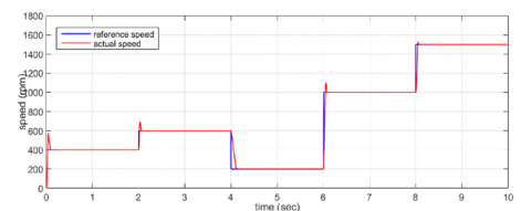
After simulated the two circuits in Figure 9 and Figure 10 a variable reference speed condition is applied to the two circuits (400 rpm-600 rpm-200 rpm-1000 rpm and 1500 rpm) at time (0sec,2sec,4sec,6sec,8sec,10sec) respectively, in order to compare the results of the two controller. Figure 11 shows the results of PI speed control of DC motor under variable reference speed, these results give zero steady state error, large over shot under sudden change of reference speed. Figure 12 shows the results of ANN speed control of DC motor under variable reference speed, these results also give zero steady state error, very small overshot under sudden change in the reference speed. Figure 13 shows the transient response of the two controller when the reference speed is constant 1000 rpm and sudden change in load torque (no load to 40 Nm load torque) at 2 second.
From the results obtained in Figures 11 and 12, we observe that the system under ANN controller gave a good response, low peak overshot, small value of settling time, zero steady state error at the sudden change in the reference speed. While the results that noted in the system under PI controller a high value of peak overshot, large value of settling time, zero steady state error) at the same conditions. Also, from Figure 13 we prove that the results of the transient response that’s obtained from ANN controller when sudden change of load torque is quick and better than the results of PI controller. The comparison between two controller in the transient response parameters is listed in Table 2.
Figure 11. Speed control of SEDC based on PI controller
Figure 12. Speed control of SEDC based on ANN controller
Figure 13. Speed response of the two controller at reference speed 1000 rpm when step change at 2sec from no load to full load (40 Nm)
Table 2. Time response parameters
|
|
Peak over Shoot % |
Peak Time tp (sec) |
Rise Time tr (sec) |
Setting Time (sec) |
|
PI |
21.1346 |
0.096 |
0.0478 |
0. 854 |
|
ANN |
3.3017 |
0.076 |
0.0478 |
0.0854 |
In this manuscript Artificial Neural Networks (ANNs) and Proportional-Integral PI controller were used to estimate and control the speed of a separately excited DC motor (SEDCM). First PI controller is designed, analyses and simulated for the SEDCM drive by a buck converter using matlab program, then ANN is trained for speed control under variable reference speed and load torque using a large example pattern, a Levenberg-Marquardt back-propagation algorithm is used in ANN training. The SEDCM based the two controller is simulated and tested under variable reference speed and variable load torque, the results show that the two controller give a zero steady state error, but ANN speed control techniques provide accurate control and quick response especially at sudden change in load or reference speed as compared with PI controller.
[1] Nutenki, R., Varma, B.V. (2024). PID controller design for DC motor speed control. In 2024 Fourth International Conference on Advances in Electrical, Computing, Communication and Sustainable Technologies (ICAECT), Bhilai, India. https://doi.org/10.1109/icaect60202.2024.10469124
[2] Alhanjouri, M. (2015). Speed control of DC motor using artificial neural network. International Journal of Science and Research, 6(2): 2140-2148.
[3] Ahmad, M.A., Kishor, K., Rai, P. (2014). Speed control of a DC motor using controllers. Automation, Control and Intelligent Systems, 2(6-1): 1-9. https://doi.org/10.11648/j.acis.s.2014020601.11
[4] Chen, G., Shang, X. (2014). Simulation used in education for a separately excited DC motor. World Transactions on Engineering and Technology Education, 12(1): 14-19.
[5] Suman, S.K., Giri, V.K. (2016). Speed control of DC motor using optimization techniques based PID controller. In 2016 IEEE International Conference on Engineering and Technology (ICETECH), Coimbatore, India pp. 581-587. https://doi.org/10.1109/ICETECH.2016.7569318
[6] Soumana, R.A., Saulo, M.J., Muriithi, C.M. (2022). Enhanced speed control of separately excited DC motor using fuzzy-neural networks controller. In 2022 4th International Conference on Smart Systems and Inventive Technology (ICSSIT), Tirunelveli, India, pp. 729-736. https://doi.org/10.1109/ICSSIT53264.2022.9716556
[7] Sharma, Y. Patra, A. (2015). Comparative analysis of PI and PID controllers for speed control of DC shunt motor. International Journal of Science, Engineering and Technology Research, 4(8): 2736-2739.
[8] Flores-Morán, E., Yánez-Pazmiño, W., Espín-Pazmiño, L., Carrera-Manosalvas, I., Barzola-Monteses, J. (2020). Particle swarm optimization and genetic algorithm PID for DC motor position controllers. In 2020 IEEE ANDESCON, pp. 1-6. https://doi.org/10.1109/ANDESCON50619.2020.9272127
[9] Ibrahim, M.A., Hamoodi, A.N., Salih, B.M. (2020). PI controller for DC motor speed realized with simulink and practical measurements. International Journal of Power Electronics and Drive System, 11(1): 119-126. https://doi.org/10.11591/ijpeds.v11.i1.pp119-126
[10] Naik, A.K., Kar, S.K., Sahu, B.K. (2021). Speed control of DC motor using linear and non-linear controllers. In 2021 1st Odisha International Conference on Electrical Power Engineering, Communication and Computing Technology (ODICON), pp. 1-5. https://doi.org/10.1109/ODICON50556.2021.9428996
[11] Yogesh, Gupta, S., Garg, M. (2014). DC motor speed control using artificial neural network. International Journal of Modern Communication Technologies and Research, 2(2): 19-24.
[12] Nagarajan, R., Sathishkumar, S., Deepika, S., Keerthana, G., Kiruthika, J.K., Nandhini, R. (2017). Implementation of chopper fed speed control of separately excited DC motor using PI controller. International Journal of Engineering and Computer Science (IJECS), 6(3): 20629-20633. https://doi.org/10.18535/ijecs/v6i3.42
[13] Azman, M.A.H., Aris, J.M., Hussain, Z., Samat, A.A.A., Nazelan, A.M.I. (2017). A comparative study of fuzzy logic controller and artificial neural network in speed control of separately excited DC motor. In 2017 7th IEEE International Conference on Control System, Computing and Engineering (ICCSCE), pp. 336-341. https://doi.org/10.1109/ICCSCE.2017.8284430
[14] Hamoodi, S.A., Sheet, I.I., Mohammed, R.A. (2019). A Comparison between PID controller and ANN controller for speed control of DC Motor. In 2019 2nd International conference on electrical, communication, computer, power and control engineering (ICECCPCE), pp. 221-224. https://doi.org/10.1109/ICECCPCE46549.2019.203777
[15] Almawla, A.M., Hussein, M.J., Abdullah, A.T. (2024). A comparative study of DC motor speed control techniques using fuzzy, SMC and PID. Journal Européen des Systèmes Automatisés, 57(2): 397-406. https://doi.org/10.18280/jesa.570209
[16] Donjaroennon, N., Nuchkum, S., Leeton, U. (2021). Mathematical model construction of DC motor by closed-loop system identification technique using Matlab/Simulink. In 2021 9th International Electrical Engineering Congress (iEECON), Pattaya, Thailand, pp. 289-292. https://doi.org/10.1109/IEECON51072.2021.9440305
[17] Sahana, M., Angadi, S., Raju, A.B. (2016). Speed control of separately excited dc motor using class a chopper. In 2016 International Conference on Circuits, Controls, Communications and Computing (I4C), pp. 1-6. https://doi.org/10.1109/CIMCA.2016.8053296
[18] Ibrahim, M.A., Ibrahim, W.K., Hamoodi, A.N. (2020). Design and implementation of overcurrent relay to protect the transmission line. International Journal of Engineering Research and Technology, 13(11): 3783-3789. https://doi.org/10.37624/IJERT/13.11.2020.3783-3789
[19] Farahani, G., Rahmani, K. (2019). Speed control of a separately excited DC motor using new proposed fuzzy neural algorithm based on FOPID controller. Journal of Control, Automation and Electrical Systems, 30: 728-740. https://doi.org/10.1007/s40313-019-00485-8
[20] Abdullah, A.G., Sh Aziz, M., Hamad, B.A. (2020). Comparison between neural network and P&O method in optimizing MPPT control for photovoltaic cell. International Journal of Electrical & Computer Engineering (2088-8708), 10(5): 5083. https://doi.org/10.11591/ijece.v10i5.pp5083-5092
[21] Al-Jawady, N.A.A.B., Ibrahim, M.A., Khalaf, L.A., Abed, M.N. (2023). An intelligent overcurrent relay to protect transmission lines based on artificial neural network. International Journal of Power Electronics and Drive Systems (IJPEDS), 14(2): 1290-1299. https://doi.org/10.11591/ijpeds.v14.i2.pp1290-1299
[22] Alnaib, A.M.T.I., Abdullah, A. (2023). Practical implementation of modified converter. Nucleation and Atmospheric Aerosols. https://doi.org/10.1063/5.0119301
[23] Hamoodi, A.N., Ibrahim, M.A., Salih, B.M. (2022). An intelligent differential protection of power transformer based on artificial neural network. Bulletin of Electrical Engineering and Informatics, 11(1): 93-102. https://doi.org/10.11591/eei.v11i1.3547
[24] Abdullah, A.G., Ibrahim, M.A., Ibrahim, W.K. (2024). Detection and identification of fault in transmission lines based on ANN. Diagnostyka, 25: 1-7. https://doi.org/10.29354/diag/185958