Mochamad Subchan Mauludin*![]() | Moh. Khairudin
| Moh. Khairudin![]() | Rustam Asnawi
| Rustam Asnawi![]() | Singgih Dwi Prasetyo
| Singgih Dwi Prasetyo![]() | Noval Fattah Alfaiz
| Noval Fattah Alfaiz![]() | Zainal Arifin
| Zainal Arifin![]()
© 2024 The authors. This article is published by IIETA and is licensed under the CC BY 4.0 license (http://creativecommons.org/licenses/by/4.0/).
OPEN ACCESS
The development of science and technology has experienced such rapid growth, thus encouraging humans to try to overcome all problems that arise around them and ease the work around the environment through automatic control systems. One of the technologies currently being developed is the Arduino microcontroller. Based on the problems often experienced by students when leaving clothes to dry in the dormitory. If it rains or bad weather, it can be a problem if you do not have time to lift the clothesline so that dry clothes become wet with rainwater when there are no dorm residents because they are on campus. Given these problems, the author designed an automatic drying room prototype using a rain sensor and light sensor based on an Arduino microcontroller. The components used are a drying room and roof, a light sensor and water sensor as input, an Arduino microcontroller, breadboard and jumper cables, a power bank as a processor, and a servo motor and LED lights as output. A servo motor automatically moves the roof of the clothes' drying room, and the LED lights turn on, according to input from the light sensor and rain sensor, according to the conditions received by the sensor.
prototype, design, automatic clothesline, Arduino
College students face significantly greater responsibilities and a more demanding schedule than their secondary education counterparts. They are expected to maintain a high level of discipline as they navigate a variety of academic and extracurricular activities, which often span both campus and dormitory life [1]. Campus activities such as lectures, organizations, research, and committees are essential for students to enhance their knowledge and experience. As a result, a significant amount of their time and energy is consumed by campus activities [2]. These campus obligations often lead to the neglect of specific duties in the dormitory.
One of the routine activities frequently undertaken by students in dormitories is the washing and drying personal clothing. The washing process can be efficiently completed using a washing machine. However, drying remains time-consuming, as it typically depends on solar energy to dry the clothes. Students often have to leave their clothes unattended while continuing academic activities on campus [3]. This situation can result in insufficient time to retrieve the clothes when unexpected rain occurs. Such sudden weather changes can cause significant inconvenience for students, particularly when the clothes are needed for the following day [4]. Consequently, there is a pressing need for the development of smart home technology that can assist students in drying their clothes autonomously without the concern of weather-related disruptions.
Technological advancements have significantly provided students with sophisticated tools to enhance their learning experiences and practical applications. One such technology is the automatic control system, which is increasingly being integrated into various fields of study, including engineering, mechatronics, and automation [5-7]. The basic concept of control has existed since the 18th century, pioneered by James Watt, who created a steam engine control. Nyquis (1932) created a closed money control system, Hazem (1943) made a mechanical servo, and many others [8]. As science and technology continue to advance, automatic control systems have increasingly enabled humans to address a wide range of challenges in more efficient and effective ways. These systems have streamlined complex processes, allowing tasks that once required significant human oversight to be managed with minimal intervention. By automating routine and repetitive activities, automatic control systems have improved productivity and freed up human resources for more strategic and creative endeavors [9-11].
Based on the above background. Many college students have yet to fully address the need for an efficient drying system that can operate independently of weather conditions. The research presented in this paper is significant as it proposes the development of an automatic drying room by utilizing smart home technology to provide an efficient solution to this issue. By integrating sensors and control systems, the proposed design can detect weather changes and adjust the drying process accordingly, ensuring that clothes are dried effectively without requiring constant monitoring by the user. The development of this technology has the potential to improve student's quality of life and contribute to the broader field of smart home innovations, paving the way for further advancements in modern home systems.
The development of an automated drying prototype using the Action Research (AR) approach can be designed to enhance practical skills and theoretical understanding among students, particularly in a university setting. To develop a functional automated drying system prototype that addresses students' real-world problems, such as needing an efficient, weather-independent drying solution [12, 13]. The AR process will be carried out in iterative cycles, each consisting of planning, action, observation, and reflection.
Figure 1. Diagram of the research flow
The research was conducted over three days in a student dormitory, with strict health protocols in place to ensure safety during the pandemic. The main focus of the study was to design and implement an automatic control system for the clothes-drying process. This system was designed to address common issues students face, who often struggle to manage their laundry due to busy schedules and unpredictable weather conditions. In the initial phase, the research developed a prototype design concept to create an intelligent drying system that automatically responds to environmental changes, such as darkness or rain, without requiring manual intervention. The development and assembly of the prototype were carried out using the Design for Manufacture and Assembly (DFMA) approach, which ensured that the prototype not only met functional requirements but was also practical to produce and assemble. Once the prototype design was completed, the assembly process was undertaken, and the prototype was tested in the student dormitory environment. This testing was crucial for evaluating the effectiveness of the automatic control system in real-world conditions, particularly in its ability to detect environmental changes and adjust the drying process automatically [14].
The DFMA (Design for Manufacture and Assembly) approach is critical in selecting tools and materials to minimize the risk of design failure. It ensures that the chosen components are reliable and efficient for the intended purpose. Additionally, this methodology is applied to the device system and physical device design, which utilizes Arduino IDE software for programming. The necessary codes are developed to operate the tools within an automatic control system, ensuring the system functions as intended. Following the design and coding phase, a prototype simulation is conducted. This process is essential for validating the results of the prototype design against the automatic control device system being developed. The simulation allows for adjustments and optimizations before final production, ensuring the design’s effectiveness and reliability. The overall research flow, which encompasses these stages, is illustrated in Figure 1.
3.1 Prototype design concept
The prototype design is made in such a way that it applies to actual conditions. The prototype is an automatic clothes-drying room. Where the roof of the room is made with an automatic control system to move when it rains, or darkness covers the drying room. The dimensions of the prototype are 160 × 120 × 75 mm, and the roof is 130 × 80 mm with a thickness of 2 mm.
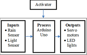
The primary process in designing this automatic clothesline is found in the Arduino Uno. Arduino Uno manages the entire circuit, including input and output. For input, we use a rain sensor and LDR. Then, for production, we use a servo motor and LED lights. In this design, the servo motor functions as a driver, a motor to open and close the roof of the drying room. The design of the automatic drying room prototype block diagram can be seen in Figure 2.
Figure 2. Design block diagram
Activator
The activator is a part of the device design that functions as a voltage provider or power supply to activate all components and parts of the circuit. The voltage source for this tool is a 10000 mAh – 5V Power bank to activate the Arduino Uno and other devices.
Inputs
Input is an input component that provides signals or data to the microcontroller, which the output component will process. The input components consist of an LDR (Light Dependent Resistor) sensor and a light detection tool to determine night and day conditions by providing an analog signal from 0 to 1023, where 0 is day, and 1023 is night. The rain sensor functions as a rain detection device that provides digital signals of rain (1) and sunshine (0) to move the position of the clothes room roof.
Outputs
The output results from signal/data processing from the input component, which has been processed by the Arduino Uno and will be passed on to the next component. The output components used are a Servo motor, which functions as a driver that will move the position of the roof of the clothes room into and out of the house; LED lights function to display symbols regarding weather conditions (rainy and sunny), light conditions (day and night). The blue LED light means it is not raining and it is sunny. Meanwhile, in other conditions, the LED light is red.
The prototype block diagram will make creating prototype design condition scenarios easier. The scenario used in the automatic drying room prototype that will be simulated is that the drying room will be open if it is not raining and it is sunny. Details of the scenario of the design conditions that will be created can be seen in Table 1.
Table 1. Conditions in the prototype design
|
No |
Rain Sensor |
Light Sensor |
LED Lights |
Room Roof |
|
1. |
Receive water |
Does not receive light |
Turns on red |
Closed position (not drying) |
|
2. |
Receive water |
Receive light |
Turns on red |
Closed position (not drying) |
|
3. |
Does not receive water |
Does not receive light |
Turns on red |
Closed position (not drying) |
|
4. |
Does not receive water |
Receive light |
Lights up blue |
Open position (drying) |
3.2 Manufacturing and assembly design
A prototype design for an automatic drying room has been created using the Solidwork application Figure 3 (b) is a drying room in closed or non-drying conditions. In this condition, the room's roof will be closed when it is dark or rainy. At the same time, Figure 3 (a) is a drying room in open space or drying conditions. In this condition, the conditions are bright, and it is not raining. The components used in the automatic drying room prototype design concept can be seen in Table 2.
Figure 3. Automatic drying room prototype design (a) closed (b) open
Table 2. Manufacturing and assembly design
|
Part Number |
Part Name |
Tapping |
Counter Boring |
Drilling |
Milling |
Grinding |
Shaping |
Fillet |
Chamfering |
Other |
|
1 |
Drying room |
N |
Y |
N |
N |
N |
Y |
N |
Y |
|
|
2 |
Drying roof |
N |
N |
N |
N |
N |
Y |
Y |
Y |
|
|
3 |
Arduino |
|
|
|
|
|
|
|
Purchased |
|
|
4 |
Breadboards |
|
|
|
|
|
|
|
|
Purchased |
|
5 |
Jumper cables |
|
|
|
|
|
|
|
|
Purchased |
|
6 |
Resistors 330 |
|
|
|
|
|
|
|
|
Purchased |
|
7 |
Servo motors |
|
|
|
|
|
|
|
Purchased |
|
|
8 |
LED lights |
|
|
|
|
|
|
|
Purchased |
|
|
9 |
Light sensor |
|
|
|
|
|
|
|
|
Purchased |
|
10 |
Rain sensor |
Purchased |
Drying room and roof
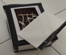
Figure 4 is a prototype of a drying room. This room is a simulation of the condition of a drying room. This component helps support the realization of the system design that has been created. I made the drying room and roof using paper and Styrofoam.
Figure 4. Prototype of drying room and roof
Arduino Uno
The primary component of an Arduino electrical kit or circuit board is an AVR microcontroller chip from the Atmel corporation. It is available for free. It is possible to program the microcontroller using a computer since it is an integrated circuit (IC) chip. A microcontroller is programmed to read input, process information, and generate the intended output to operate electrical circuits [15, 16]. Thus, an electrical circuit's input, processing, and production are all managed by the microcontroller, which functions as its brain. Similar to an Arduino in Figure 5.
Figure 5. Arduino Uno
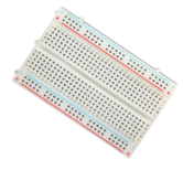
Breadboard
Breadboard is a board that is used to make electronic circuits without having to bother users with soldering. The breadboard is a conducting medium to which the jumper cables are attached [17]. So that the current from one component can be appropriately distributed as desired to other components without having to bother the user with soldering or dismantling. Shape a breadboard like Figure 6.
Figure 6. Breadboards
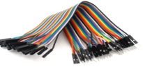
Jumper cables
Electrical wires called jumpers, including connection pins on both ends, let you connect two Arduino-related components without soldering. Jumper cables are essentially used as an electrical conductor to link electrical circuits. Jumper cables are typically used on breadboards or other prototyping equipment to facilitate circuit modification [18]. At the end of the cable, there are two different kinds of connectors: male and female. The jumper cable has a form similar to Figure 7.
Figure 7. Jumper cables
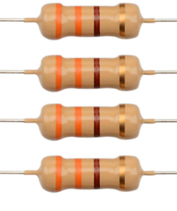
Resistors
The flow of electricity is resisted or inhibited by resistors. It can be used to safeguard delicate parts like LEDs. Little colored bands indicate the resistor's strength (in ohms) on the body. With the resistor table, one can find the unique number for each color [19]. Two 330 Ω resistors were employed in the design. The resistor's form is similar to Figure 8.
Figure 8. 330 Ω resistor
Servo motors
The Sg-90 servo motor functions as a driving motor to move the roof so that it can be opened on non-rainy days and closed if both conditions are not met. This servo motor is capable of rotating 1800. This servo motor has three pins, including [20]: the pin for GND or The negative pole is brown, the positive pole is red, and the third pin is yellow, which will be connected to the output device. The shape of a servo motor is shown in Figure 9.
Figure 9. Servo motors
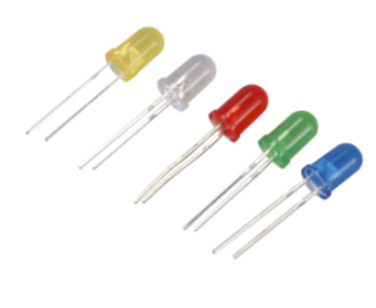
LED lights
An LED, or light-emitting diode, is a tiny bulb composed of silicon diodes. They are available in different sizes, hues, and brightness. LEDs only let electricity flow in one direction and feature a positive (+) and negative (-) leg configuration. When connecting an LED to a circuit, you should always use a resistor to control the current since LEDs can burn out if too much power passes through them. The blue LED represents drying, while the red LED indicates not drying [21]. The LED light's form is similar to Figure 10.
Figure 10. LED lights
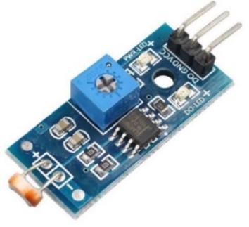
Light sensor
A resistor whose resistance value is based on the light it receives is known as a light sensor or LDR (light-dependent resistor). Bright light causes the LDR Resistance value to drop, while darkness causes the Resistance value to increase. Put differently, the light-dependent resistor (LDR) is designed to conduct electricity when exposed to a specific level of light (referred to as "light conditions") and to block electricity when exposed to darkness. The Resistance rating will rise and fall directly proportional to the quantity of light it experiences [21]. Under typical lighting circumstances, the LDR Resistance Value drops to 500 Ohm (Ω) from 200 Kilo Ohm (kΩ) in the dark. The shape of the light sensor is like that in Figure 11.
Figure 11. Light sensor
Accurate detection of day and night conditions by the light sensor in the automatic control system relies on specific thresholds of ambient light intensity, measured in units such as lux. These thresholds are predetermined based on typical light levels associated with day and night conditions. The light sensor, often a photodiode or Light Dependent Resistor (LDR), measures the intensity of light in its surroundings. During the day, light levels are significantly higher due to natural sunlight, typically ranging from around 10,000 lux on a cloudy day to over 100,000 lux in direct sunlight. Conversely, light levels drop drastically at night, often to less than 10 lux, depending on artificial lighting and environmental factors. The system uses threshold values established through calibration to differentiate between day and night. For instance, the daytime threshold may be set at 5,000 lux or above to classify the environment as daytime. Conversely, if the light intensity drops below 50 lux, the system will recognize it as nighttime. By setting these thresholds, the light sensor can effectively automate processes based on ambient light conditions, ensuring the system operates optimally in various environments.
Rain sensor
Rain sensors can also be called water sensors; the function of this sensor is to detect the presence of water. This sensor uses a panel or water detector as a detector. The way this rain sensor works is that when rainwater hits the sensor panel, an electrolysis process will occur with the rainwater because rainwater is included in the electrolyte liquid, which is a liquid that can conduct electric current, even though it is minimal. This process will cause an active state, which will activate the relay. This rain sensor functions as a water detector, which will be used to provide input to the microcontroller [22]. The shape of the rain sensor is like that of Figure 12.
Figure 12. Rain sensor
Arduino IDE
Using an IDE (Integrated Development Environment), one may create microcontroller apps by writing source code, building it, uploading the results, and testing it using a serial interface. The Arduino IDE can be seen in Figure 13. 1). The verify menu icon with a checkmark is used to check the written program for errors or errors. 2). The upload menu icon with an arrow to the proper functions to load programs created in Arduino software onto Arduino hardware. 3). The new menu icon with a figure of a piece of paper functions to create a new page in programming. 4). The Open menu icon with an upward arrow is used to open a saved program or program the Arduino software manufacturer has created. 5). The Save menu icon with a downward arrow saves programs created or modified. 6). The serial monitor menu icon with the image of a magnifying glass functions to send or display serial data communications when sent from Arduino hardware [23].
Figure 13. Arduino IDE
3.3 Device system design
3.3.1 Hardware
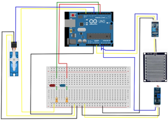
As in the figure, the hardware design consists of three parts: the input part, a water sensor module, and a light sensor module, which detects weather changes from the external environment. In the controller section, there is an Arduino Uno board for data processing from the results of the detection of changes in the external environment by the water sensor and light sensor; in the output section, there is a servo motor as an actualization of the detection results from the water sensor and light sensor from the external environment as in Figure 14 and for component positions can be seen in Table 3.
Figure 14. Prototype device design blueprint
Table 3. Position of Arduino device component
|
Pin Module |
Arduino Uno Pins |
|
Rain sensor |
|
|
Vcc |
5v pins |
|
Gnd |
Gnd pin |
|
A0 |
A0 pins |
|
Light sensor |
|
|
Vcc |
5v pins |
|
Gnd |
Gnd pin |
|
A0 |
A1 pins |
|
LED lights |
|
|
Blue |
6 pins |
|
Red |
7 pins |
|
Servo motors |
|
|
Chocolate |
Negative pin |
|
Red |
Positive pin |
|
Yellow |
9 pins |
3.3.2 Software
Hardware design that uses the Arduino Uno board as the central controller will only work if it is accompanied by software designed to control the system as a whole. This software functions as a controller and connector that regulates the steps the Arduino Uno microcontroller board must carry out in the system created. This software is designed using simplified C language. This program developed for the Arduino Uno has a working principle when light (daylight) is detected by the light sensor (LDR). The rain sensor does not detect the presence of water, so the servo motor used as a tool to move the clothesline cover will move to an angle of 100° or move to open the roof of the drying room, and the blue LED light turns on. When the light sensor does not detect light (at night), the servo motor will move to an angle of 0°, or the roof of the drying room will move to cover the clothesline. Like the light sensor, the water sensor reads the situation when the sensor is exposed to water; the servo motor will move to a 0° angle, or the clothesline roof will move to cover the clothesline. Moreover, when the sensor is exposed to water and it is dark, the servo motor will move to a 0° angle or move to close the clothesline roof.
Variables and libraries
System Construction (Coding) This discussion explains the construction of the program system in detail, including variables and libraries, program initialization, reading input, processing, controlling program output, and the functions used. Below are the variables and libraries used in creating automatic clotheslines:
#include <Servo.h>
int rainPin = A0;
int LEDgreen = 6;
int redLED = 7;
int light = A1;
int servoPosition;
Servo myservo;
To make the servo motor work, use the library, namely, #include <Servo.h>; int servoPosition; and Servo myservo; The signal reading is connected to each pin where int rainPin = A0; for rain sensor, int LEDgreen = 6; for blue LED lights, int red LED = 7; for red LED lights, while int light = A1; for light sensors.
Initialization
System Construction (Coding) This discussion explains the construction of the program system in detail, including variables and libraries, program initialization, reading input, processing, controlling program output, and the functions used. Below are the variables and libraries used in creating automatic clotheslines:
void setup(){
pinMode(rainPin, INPUT);
pinMode(greenLED, OUTPUT);
pinMode(redLED, OUTPUT);
digitalWrite(greenLED, LOW);
digitalWrite(LEDred, LOW);
pinMode(light,INPUT);
myservo.attach(9);
}
In the Arduino IDE, void setup is one of the main functions to activate the pins on the variables set and the initial configuration needed to start the primary process.
Input
In an automatic clothesline, the input process is carried out by sensors. The data generated from the sensor will be processed in the form of voltage. This data measures the voltage level produced and the conditions that can be created. The following is the command used to read the value
void loop() {
int sensorValue = analogRead(rainPin);
int data = analogRead(light);
In the Arduino IDE, void loop is a loop function that works to repeat the reading of the command when the last command in this function is read. This function is one of the main functions for placing commands that are used so that the tool can work.
Main program & output
After the sensor inputs data, it will continue to determine the condition of the drying roof, light, and weather. This aims to determine where the roof of the drying room will be placed and when the LED lights will turn on. The following are the main conditions used to process input. After reading the conditions, it will be continued by moving the servo motor in the direction determined by the conditions created in making the automatic clothesline.
if(sensorValue > 800 && data < 700){
digitalWrite(redLED, HIGH);
digitalWrite(greenLED, LOW);
myservo.write(100);
}
else {
digitalWrite(LEDred, LOW);
digitalWrite(greenLED, HIGH);
myservo.write(10);
}
delay(500);
}
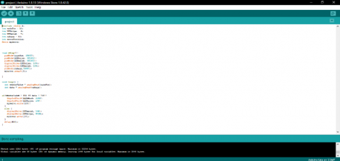
The conditions above result from readings from the sensor conditions, which will then be applied to the output components and make the tool work according to the weather conditions detected by the sensor. After creating the code, it is verified and uploaded using the Arduino IDE software. The final coding has been successfully verified and uploaded in Figure 15.
Figure 15. Design coding results
3.4 Simulation of design results prototype
Testing the automatic drying room prototype system using an Arduino-based Water Sensor and Light Sensor aims to determine whether the prototype system created can work well or according to what was planned. Testing Method Prototype system testing can be done as follows:
1. Install the required components according to the design blueprint.
2. Connect the Arduino Uno board to the laptop using a USB cable, create a sketch program for the entire prototype, and upload the sketch to the Arduino Uno R3 board.
3. Connect the USB cable to the Arduino Uno R3 board as a voltage source for the Arduino board.
4. After the prototype is lit, it is sprinkled with water on the rain sensor to indicate the presence of raindrops and then the water on the rain sensor to indicate the absence of raindrops. Next, it provides light rays to the light sensor as an indicator of daylight and closes the light sensor from light rays as an indicator of nighttime or dark conditions. After testing the prototype design system, it was seen that the prototype system could function because the components used worked in the correct order. The prototype works as shown in Figure 16.
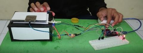
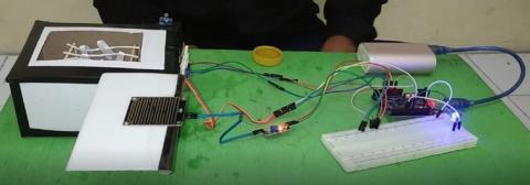
From the prototype simulation process, the results were obtained: If the rain sensor does not detect water/dry (from threshold <800) and the light sensor detects light/bright (from threshold > 700), then the servo motor moves from an angle of 0° to an angle of 110° indicating that the clothesline roof moves open and the color LED lights blue lights up as an indicator of drying as shown Figure 17. Moreover, suppose one or both conditions are not met. In that case, the servo motor moves from an angle of 110° to an angle of 0°, indicating that the drying roof is moving close, and the red LED light turns on as an indicator of not drying as intended in Figure 18.
Figure 16. Prototype workflow
Figure 17. Prototype of drying room with automatic drying position
Figure 18. Prototype of automatic drying room in a non-drying position
The prototype of the automatic drying room has been successfully designed, marking a significant breakthrough in the development of smart home technology. This model demonstrates a functional solution and offers an innovative approach to automating the clothes-drying process. By utilizing sensor technology and microcontrollers, this prototype can provide an efficient and reliable solution for tackling the challenges of clothes drying, particularly in unpredictable weather conditions. Key findings from the evaluation indicate that the drying room's roof can automatically move according to the weather conditions detected by the sensors. When the sensors detect changes in light or rainfall, the servo motor will move the roof to protect the clothes from rain or allow optimal drying when the weather conditions are favorable. Additionally, the LED lights in this system will adjust their intensity based on the data received from the light sensor, serving as a visual indicator of the drying status.
This research indicates that the automatic drying device can operate under four different conditions: bright light sensor with dry sensor, dark light sensor with dry sensor, bright light sensor with wet sensor, and dark light sensor with damp sensor. This adaptability enhances the device's usability in various weather conditions, providing a reliable solution for automatic clothes drying. To optimize accuracy and responsiveness, performance improvements of the prototype through integrating more advanced components are necessary. These enhancements could result in a smoother and more efficient drying system. Additionally, automatic drying could be expanded to include functionality that ensures clothes can dry effectively even when shaded or during rainfall, offering a more comprehensive solution for drying clothes in diverse environments.
This research is part of the doctoral dissertation research of engineering science at Yogyakarta State University.
[1] Pillai, A.K., Vieta, M.A., Sotomayor, L. (2021). University student housing as business proposition and entrepreneurial activity: The Canadian case. Housing Policy Debate, 1-24. https://doi.org/10.1080/10511482.2021.1883703
[2] Caesari, Y.K., Listiara, A. (2013). Kuliah versus organisasi” studi kasus mengenai strategi belajar pada mahasiswa yang aktif dalam organisasi mahasiswa pecinta alam universitas diponegoro. Jurnal Psikologi, 12(2): 164-175. https://doi.org/10.14710/jpu.12.2.164-175
[3] Yamaguchi, Y., Chen, C.F., Shimoda, Y., Yagita, Y., Iwafune, Y., Ishii, H., Hayashi, Y. (2020). An integrated approach of estimating demand response flexibility of domestic laundry appliances based on household heterogeneity and activities. Energy Policy, 142: 111467. https://doi.org/10.1016/j.enpol.2020.111467
[4] Darusman, A.D., Dahlan, M., Hilyana, F.S. (2018). Rancang bangun prototype alat penjemur pakaian otomatis berbasis Arduino Uno. Simetris: Jurnal Teknik Mesin, Elektro Dan Ilmu Komputer, 9(1): 513-518. https://doi.org/10.24176/simet.v9i1.2077
[5] Tyagi, A.K., Fernandez, T.F., Mishra, S., Kumari, S. (2020). Intelligent automation systems at the core of industry 4.0. In International Conference on Intelligent Systems Design and Applications, pp. 1-18. https://doi.org/10.1007/978-3-030-71187-0_1
[6] Khairudin, M., Refalda, R., Yatmono, S., Pramono, H.S., Triatmaja, A.K., Shah, A. (2020). The mobile robot control in obstacle avoidance using fuzzy logic controller. Indonesian Journal of Science and Technology, 5(3): 334-351.
[7] Khairudin, M., Hastutiningsih, A.D., Maryadi, T.H.T., Pramono, H.S. (2019). Water level control based fuzzy logic controller: Simulation and experimental works. IOP Conference Series: Materials Science and Engineering, 535(1): 012021. https://doi.org/10.1088/1757-899X/535/1/012021
[8] Handoko, K. (2017). Perancangan prototype jemuran pakaian otomatis menggunakan sensor ldr dan sensor basah berbasis arduino alvia setyaji. Koko Handoko.
[9] Parapat, A., Syaechurodji, S. (2020). Rekayasa Perangkat Lunak Alat Kendali Jemuran Otomatis Menggunakan Arduino Dan Sensor Hujan/Air, Kelembaban Dht11 Dan Cahaya Ldr. Jurnal Ilmiah Sains Dan Teknologi, 4(1): 19-26.
[10] Nadik, J., Mauluddin, M.S., Mustagfirin, M. (2017). Aplikasi Rebana Digital Berbasis Android. Prosiding Sains Nasional dan Teknologi, 1(1): 1886. http://dx.doi.org/10.36499/psnst.v1i1.1886
[11] Mauludin, M.S., Alfalah, A.F., Wibowo, D.D. (2016). MQ 2 sebagai sensor anti asap rokok berbasis arduino dan bahasa C. Prosiding Sains Nasional Dan Teknologi, 1(1): 1545. http://doi.org/10.36499/psnst.v1i1.1545
[12] Arifin, Z., Prasetyo, S.D., Prabowo, A.R., Cho, J.H. (2021). Preliminary design for assembling and manufacturing sports equipment: A study case on aerobic walker. International Journal of Mechanical Engineering and Robotics Research, 10(3): 107-115. https://doi.org/10.18178/ijmerr.10.3.107-115
[13] Prasetyo, S.D., Istanto, I., Cho, J.H., Prabowo, A.R. (2021). Investigation of sulfur melter heating coil as an industrial product: A study case on technical design and structural inspection. Procedia Structural Integrity, 33: 43-50. https://doi.org/10.1016/j.prostr.2021.10.007
[14] Arifin, Z., Prasetyo, S.D., Ubaidillah, U., Suyitno, S., Tjahjana, D.D.D.P., Juwana, W.E. Rachmanto, R.A, Prabowo, A.R., Apribowo, C.H.B. (2022). Helmet stick design for BC3 paramlympic bocia games. Mathematical Modelling of Engineering Problems, 9(3): 637-644. https://doi.org/10.18280/mmep.090310
[15] Rossi, M., Toscani, N., Mauri, M., Dezza, F.C. (2021). Introduction to Microcontroller Programming for Power Electronics Control Applications: Coding with MATLAB® and Simulink®. CRC Press.
[16] Fajri, F.A.Z., Mauludin, M.S. (2020). Rancang bangun sistem keamanan aliran listrik arus AC dengan fingerprint menggunakan arduino nano. Jurnal Informatika dan Rekayasa Perangkat Lunak, 2(1): 26-31.
[17] Westcott, S., Westcott, J.R. (2020). Basic Electronics: Theory and Practice. Mercury Learning and Information.
[18] Halim, M.A., Faisal, M.R., Molla, M.A.H., Chakraborty, T. (2020). Study of eco air-cooling. Doctoral dissertation, Sonargaon University (SU).
[19] Samur, M.K., Fulciniti, M., Samur, A.A., Bazarbachi, A.H., Tai, Y.T., Prabhala, R., Alonso, A., Sperling, A.S., Campbell, T., Petrocca, F., Hege, H., Kaiser, S., Loiseau, H.A., Anderson, K.S., Munshi, N.C. (2021). Biallelic loss of BCMA as a resistance mechanism to CAR T cell therapy in a patient with multiple myeloma. Nature Communications, Nature Publishing Group UK London. 12(1): 868. https://doi.org/10.1038/s41467-021-21177-5
[20] Ali, A.W.A., Razak, F.A.A., Hayima, N. (2020). A review on the AC servo motor control systems. ELEKTRIKA-Journal of Electrical Engineering, 19(2): 22-39. https://doi.org/10.11113/elektrika.v19n2.214
[21] Pennisi, G., Blasioli, S., Cellini, A., Maia, L., Crepaldi, A., Braschi, I. Spinelli, F., Nicola, S., Fernandez, J.A., Stanghellini, C., Marcelis, L.F.M., Orsini, F., Gianquinto, G. (2019). Unraveling the role of red: Blue LED lights on resource use efficiency and nutritional properties of indoor grown sweet basil. Frontiers in Plant Science, 10: 305. https://doi.org/10.3389/fpls.2019.00305
[22] Giannetti, F., Lanza, L.G. (2023). Special issue “rain sensors.” Sensors, 23(15): 6934. https://doi.org/10.3390/s23156934
[23] Lenni, L., Ajis, A. (2018). Rancang bangun atap jemuran pakaian otomatis menggunakan sensor hujan, sensor LDR, sensor infra red dan remote berbasis Arduino Uno R3. Dinamika Umt, 2(2): 58-77. http://doi.org/10.31000/dinamika.v2i2.1438