Ahmed S. Rahi*![]() | Shamam F. Alwash
| Shamam F. Alwash![]()
© 2024 The authors. This article is published by IIETA and is licensed under the CC BY 4.0 license (http://creativecommons.org/licenses/by/4.0/).
OPEN ACCESS
Microgrids (MGs) are an integral part of smart energy systems. Hybrid renewable energy sources necessitate a trustworthy control strategy for optimal coordination and utilization of these systems. Improving Microgrid DC MG is the primary goal of this study, which focuses on power management in bidirectional DC-DC converters through the local control unit. Problems brought on by changes in power production and interruptions in load are examined. A hierarchical control strategy addresses these issues with primary layer droop control. This study aims to manage energy by examining variations in photovoltaic systems, batteries, and supercapacitors. Energy management efficiency is defined by the design of the control circuits and converters. Diagrammed. Responsiveness and absence of overshoot/undershoot show that the system is effective and resilient in handling DC MG local control problems, regardless of the load or generation conditions.
power management, DC microgrids, bidirectional DC-DC converters
Microgrids present a compelling alternative to transmitting power from distant generations, offering several advantages in design and implementation cost, dependability, and durability [1, 2]. Researchers and industrialists have increasingly focused on Low Voltage Direct Current (LVDC) microgrids due to their reliability, robustness, economics, power quality, and distribution efficiency [3]. While alternating current (AC) microgrids have their merits, direct current (DC) microgrids outperform them in supply loss, control algorithm complexity, dependability, and long-term viability [4].
An LVDC microgrid is typically constructed using Distributed Energy Resources (DERS) such as photovoltaic (PV) panels, wind turbines, diesel generators, and Hybrid Energy Storage Systems (HESS) like Battery Energy Storage Systems (BESS) and supercapacitors (SC), all connected to a DC bus. Integrating large-scale renewable energy sources is crucial for sustainable energy production, as they are environmentally beneficial and have an unlimited supply [5-7]. However, their intermittent output raises extreme caution about meeting energy demands during non-production periods. Unfortunately, this approach contradicts the goal of minimizing fossil fuel usage, therefore, it is essential to fully appreciate the significance of renewable energy and prioritize increasing production and the share of the system load provided by renewables [8, 9].
Standalone renewable energy generation projects have been initiated, particularly in developing countries, to improve accessibility and address rural energy needs in an affordable and eco-friendly manner [10, 11]. Energy security is a significant concern, as price volatility in fossil fuels can disrupt supply. To mitigate this, local renewable energy (RE) solutions that diversify supply options and reduce reliance on imported energy are crucial [12]. The intermittent nature of renewable sources can pose stability challenges when they constitute a significant portion of the power grid. Energy storage systems (ESSs) are vital in enhancing system resilience and optimizing operational costs by reducing power fluctuations and providing flexible RE dispatch [13].
BESSs are often used in wind energy generation systems to balance demand during periodic variations [14]. Integrating ESSs with built-in virtual inertia can address demand mismatches, improper sharing, voltage management issues, and power quality concerns caused by renewables [9, 15]. Researchers have explored various techniques to improve the reliability of standalone renewable energy systems. Dynamic thermal rating systems and battery charge/discharge rate factors have been applied to address the reliability of wind energy systems [16]. Multiobjective optimization using evolutionary algorithms has been suggested for enhancing PV/wind power system dependability [17].
The recent focus has been on standalone renewable energy systems with HESS integration, aiming to create multi-energy storage systems to boost power production and lower microgrid costs [18, 19]. HESSs are critical in meeting urgent energy needs, with high power and energy densities being crucial factors [20]. Effective control techniques are essential to ensure battery longevity and prevent overcharging or deep discharge to meet energy storage demands. Combining batteries and supercapacitors in microgrids enhances performance during source variations and load changes [20].
Energy storage and intelligent control strategies made possible by microgrids offer a promising, sustainable, and reliable solution for energy distribution, management, uninterruptibility, and security. This is especially true for low-voltage, low-voltage microgrids.
This paper proposes a hybrid PV-battery/supercapacitor multilayer control strategy to address various issues. The key features are:
The paper's overview builds on the models presented in Section 2, depicting a DC microgrid system complete with ESS devices, constant power, and resistive loads. Section 3 describes the proposed hybrid control strategy for the system. In addition, Section 4 presents the design of the bidirectional buck-boost converter for the ESS. Section 5 provides simulation results and discusses the proposed controller's performance. Finally, Section 6 concludes the paper and highlights the results and contributions achieved.
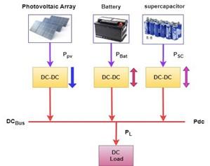
Figure 1 illustrates the configuration of the DC microgrid analyzed in this study. The microgrid comprises various components, including a battery, a supercapacitor, a distributed generator, and a DC load, all interconnected to the DC bus. A power electronic converter links these sources and loads, facilitating their integration into the DC microgrid. The distributed generator fulfils the power demand of the DC loads. To maintain a steady state in the DC microgrid's power balance, the battery controller controls the charging or discharging of the batteries accordingly. On the other hand, the supercapacitor requires a control design strategy to supply variable power demands.
Figure 1. Power flow of PV system with battery and supercapacitors as source and storage elements
The proposed DC system's energy flow will be integrated with the AC network. The total power generated by the PV system and the storage system, consisting of the battery bank and supercapacitor bank, is determined as follows:
$P_{d c}=P_{P V}+P_{B A T}+P_{S T}$ (1)
$P_{S T}=P_{B A T}+P_{S C}$ (2)
Therefore, the above system operates in three modes:
Charging mode: The PV system generates more power than needed during charging. Excess energy charges batteries and supercapacitors. This mode efficiently stores surplus energy for later use, reducing waste and improving microgrid energy efficiency.
$P_{P V}>P_L$ (3)
Discharge mode: Discharging occurs when load demand exceeds PV power. This mode releases battery and supercapacitor energy to bridge the gap and meet load requirements. This ensures a consistent power supply, improving microgrid reliability during low generation or peak demand.
$P_{P V}<P_L$ (4)
Idle mode: PV power matches load demand in idle mode. This eliminates the need to charge or discharge the ESS. This balanced state maximizes power utilization, reducing storage system cycling and extending lifespan.
$P_{P V}=P_L$ (5)
This paper will examine all the above modes in the simulation results sections. Below, will discuss how simulated the battery, supercapacitors, distributed generator, and DC load.
3.1 DC MG control
Dealing with the intermittent nature of distributed energy resources like PV, WTG (Wind Turbine Generator), and fuel cells, a typical MG also includes ESSs [10, 11]. Typically, these sources supply the system with DC electricity, though rectified AC power from WTGs is also possible [12]. By conforming to the IEEE Standard 1547, which regulates the interconnection and interoperability of distributed renewable energy resources, capping distributed renewable energy resources at 5% ensures that DC MG is an optimal energy coordination and management technique [13]. Hierarchical local and global control techniques have been developed [13, 14]. A hierarchical control approach consists of three distinct layers of control: the primary or local layer, the intermediate level layer, and the outer or global layer. The local layer's mission is to ease the flow of authority between various DGSs to account for voltage fluctuations. The secondary level is designed to stabilize the system further, while the third stage focuses on controlling energy flow between microgrids (MGs) and the more extensive electrical system [12].
3.2 PV side control strategy
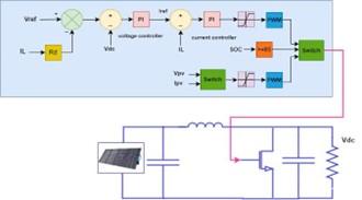
The PV system supplies the DC Microgrid (DC MG) with readily available DC power and serves as the primary source of the DC Microgrid (DC MG); it makes it so that DC electricity does not have to be converted into another kind of energy. Nevertheless, the regulation of voltage and power output in the photovoltaic (PV) system is lacking, hence lacking a guarantee of consistent adherence to the system's established criteria. [15]. Consequently, a direct connection to a common DC link (It means connecting direct current in one bus bar) is not possible unless DC-DC converters are utilized in the process. These converters have precise control because they are essential to stabilizing the DC bus. As shown in Eq. (1), the DC-DC converter operates in the droop mode and the maximum power point tracking (MPPT) mode. In the droop mode, the DC-bus voltage is adjusted to match the varying load, mainly when there is low power demand or the battery has been fully charged [16]. However, the MPPT mode will adjust to compensate for the power fluctuations even if the DC-link voltage is unstable. This model is frequently used in PV systems to ensure that the full potential of renewable energy sources [16, 17] is realized. Eq. (6) is an expression that can describe the output voltage of the droop-controlled converter.
$D \begin{cases}\left(I_{\text {ref }}-I_L\right)\left(K_{P p v}+\frac{K_{i p v}}{s}\right) & s o c \geq S O C_{\max } \\ D_{m p p t} & s o c \geq S O C_{\min }\end{cases}$ (6)
where, IL represents the current output by the converter, Iref represents the reference value of that current, SOC represents the state of charge and its minimum and maximum values, and Dmppt represents the duty cycle when operating in MPPT mode. Furthermore, KPpv and Kipv indicate the parameters of the present controller in Figure 2. Eq. (6) demonstrates that voltage stabilization can be precisely regulated under varying operational situations by adjusting the battery's SoC threshold.
3.3 Hybrid battery/SC side control strategy
Energy Storage Systems (ESSs) are necessary to effectively satisfy load demand in the presence of intermittent Renewable Energy Sources (RES) such as photovoltaic and wind turbine generators. Including a battery storage system is necessary to regulate voltage and power balance inside the microgrid. In this investigation, the droop control method is applied to keep the DC-bus voltage stable while simultaneously guaranteeing the automatic charging and discharging of the battery [18].
It is possible to achieve efficient operation of the ESS by combining batteries and supercapacitors (SCs), which have a high power density but are less bulky than batteries. On the other hand, batteries have a high energy density but a lower power density, which limits the speeds at which they can discharge or charge [19, 20]. Batteries are primarily responsible for power generation in this context, whereas SCs manage transient fluctuations in localized load and deal with power peaks during unforeseen conditions [21]. The effectiveness of the microgrid was found to be significantly improved by integrating a hybrid energy storage system (HESS) in a variety of load and PV-generation configurations throughout this study.
The SC collects high-frequency components, thereby reducing the load on the main battery and ensuring a healthy DC bus voltage level. Additionally, it serves as a safeguard for batteries against severe discharge and overcharging, effectively extending their service life [22].
As shown by Eqs. (7) and (8) that describe the energy-generating structure of a hybrid battery/SC system:
$\delta_b=\left(I_{b r e f }-I_b\right)\left(K_{a_{b a t}}+\frac{K_{i_{b a t}}}{s}\right)$ (7)
$\delta_{s c}=\left(I_{s c r e f}-I_{s c}\right)\left(K_{P_{s c}}+\frac{K_{i_{s c}}}{s}\right)$ (8)
KaBAT and KiBAT represent the battery controller's parameters, and Ibref and Ib are nominal and actual battery currents, respectively. As shown in Figure 2, Kpsc and Kisc represent the parameters of the supercapacitor controller, while Isc and Iscref represent the SC current and its reference, respectively. Pulse-width modulation (PWM) generators create switching pulses (SWb1 and SWb2) for the bidirectional battery converter and (SWsc1 and SWsc2) for the bidirectional supercapacitor converter based on the difference between the currents in each of the two sources. Pulse-width modulation (PWM) generators play a crucial role in the control strategy of a DC microgrid by regulating the voltage and current flow to maintain stable and efficient operation of the microgrid components. PWM generators achieve this by adjusting the duty cycle of the switching devices, such as MOSFETs, in power electronic converters.
(a)
(b)
Figure 2. Proposed control strategy, (a) PV system, (b) hybrid storage system
In Figure 2, it can see the DCMG as it appeared in a MATLAB simulation. At this stage, it is required to establish the requirements of MGs in typical operation conditions, from which the specifications of PV arrays and hybrid batteries/SCs can be derived. It is also necessary to design DC-DC and bidirectional converters, considering the system's RESs, ESSs, and other needs. Accordingly, the design considerations of such converters are given in the following subsections to provide a clear understanding of designing converters for various MGs.
4.1 Boost converter
As a result of their simple design, durability, usability, and low cost, these converters find widespread employment in MGs [23]. These converters bring the PV system's output voltage up to spec and implement maximum power point tracking. Specifically, Eqs. (9) and (10) must be used to determine the ideal values for the inductor Lboost and the capacitance Cboost in order to optimize the converter's performance in the investigated Microgrid )MG ( [23, 24].
$\mathrm{L}_{\text {boost }}=\frac{V_O D(1-D)}{2 \Delta I_1 \times F_S}$ (9)
$\mathrm{C}_{\text {boost }}=\frac{V_i D(1-D)}{8 \times \Delta V_o \times F_s^2 \times \mathrm{L}_{\text {boost }}}$ (10)
$V_o=\frac{V_i}{(1-D)}$ (11)
$I_o=\frac{p_L}{V_o}$ (12)
In this context, $I_o$ denotes the output current, and ∆IL denotes the ripple in the inductor current. The individual symbols for output power (PL), switching frequency (Fs), input voltage (Vi), duty cycle (D), and output voltage (Vo) with ripple (DVo) are defined. The critical values for DVo and ∆IL are 5% and 30% of the output current, respectively, as determined by Eqs. (11) and (12), respectively. In order to construct a boost converter that can supply power to the DC bus of the system, it is necessary to take all of these equations into account. The performance of the boost converter in a microgrid is highly dependent on the values of the inductor (Lboost) and capacitor (Cboost). Though it may be larger, more expensive, and slower to respond, a more significant inductor decreases current ripple and component stress. Although a larger capacitor enhances stability and decreases voltage ripple, it may also increase size and ESR, which impacts efficiency. For the converter to function optimally within the microgrid, it is necessary to optimize these values to balance current and voltage ripple, efficiency, and response time.
4.2 Buck-boost converter
Energy storage is essential to a solar power system. The MGs use a regular bidirectional DC/DC converter to regulate the charging and discharging of their batteries, depending on the system's state. The inductor LBAT and capacitor CBAT must be precisely determined using the following Eqs. (13) and (14) for the converter to function optimally [23, 24].
$L_{B A T}=\frac{V_i \times D_{\mathrm{BAT}}}{\Delta I_1 \times F_S}$ (13)
$C_{B A T}=\frac{I_o D}{\Delta V_o \times F_s}$ (14)
$V_o=\frac{D V_i}{(1-D)}$ (15)
In boost mode, Fs and D denote switching frequency and duty cycle, respectively, which can be calculated using Eq. (13). Vi and DBAT stand for battery voltage and converter duty cycle, respectively. Please take note that the rated output voltage (VO) and the output current (Io) must both fall within the 20% to 30% range, while the rated direct current voltage (DVo) is set to 5% of the rated direct current voltage (Vdc). These equations are necessary for the construction of a buck-boost converter. The Buck-Boost converter uses pulse width modulation (PWM) as its pulse control technique; the produced signal is a square wave with perfect parameters that ensure the transistor's operation and the switching-off process.
The load changes and solar irradiation fluctuations were simulated in various scenarios to validate the proposed method's efficacy in enhancing the performance of local control layers in the DC microgrid. The simulation setup included a PV array consisting of six panels, each rated at 120.7 W, supplying 724.6 W, and a 14 Ah, 24 V battery with a 50% state of charge (SoC). The system also included a load rated at 48 V, 300 W, as detailed in references [25, 26].
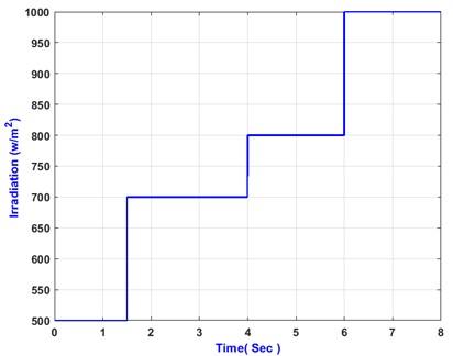
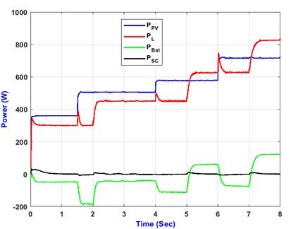
Specific scenarios with load changes and solar irradiation fluctuations were created to assess the system's response. The load varied by 50%, 38%, and 32%, while solar irradiation fluctuated at intervals of 1.5s, 4s, and 6s, as indicated in Figure 3. At the initial state (0s), the PV system generated 300W, which met the load demand, and any excess power was used to charge the battery to a safe SoC level. As the load demand increased to 450W, the PV generation remained constant at 450W until 4s, leaving no surplus power to charge the battery during the 1s to 2s interval.
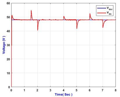
These scenarios demonstrated significant variations in the DC-link voltage due to the fluctuations. At 1s, the voltage dropped dramatically, as shown in Figure 4, while at 4s, it peaked at 50.25 V when PV generation reached 625W. The bus voltage deviated unacceptably from the standard limit of 5% during 1s, 3s, and 4s due to the different rates of increase in load demand at those times. These results indicate that the traditional control method struggles under varying operational conditions.
Additionally, some undesirable ripples remained while the battery current closely followed the reference value, as illustrated in Figures 5-9. The system demonstrated unresponsiveness to induced disruptions, indicating issues with reliability and stability. These findings underscore the need for an improved control strategy to handle dynamic load and solar irradiation changes effectively. These results and component ratings are referenced in the studies [25, 26].
Figure 3. Irradiation profile
Figure 4. Voltage response under variable load and irradiance
Figure 5. Power management of hybrid system based on variable load and irradiance
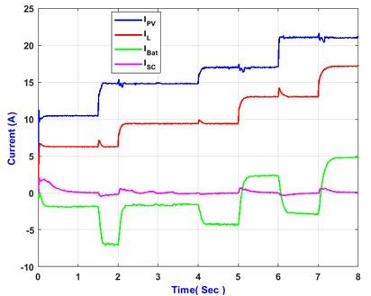
Figure 6. The data demonstrates the nature of the response of PV current, load current, battery current, and supercapacitor current, respectively
Figure 7. Battery current under variable load and irradiance
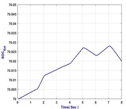
Figure 8. The battery's state of charge (SoC)
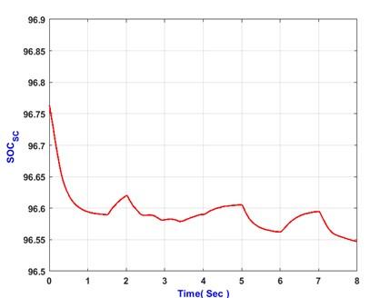
Figure 9. The battery's state of charge (SoC) supercapacitor
Using the proposed control strategy, the simulation results significantly impact real-world microgrid (MG) systems. The strategy improves stability and control by managing dynamic load changes and solar irradiation fluctuations, optimizing energy use and power flow. Scalability suggests suitability for various MG configurations and sizes. Complex control algorithms and multiple control layers make implementation difficult, requiring advanced hardware software and higher setup costs. Unresponsiveness to rapid fluctuations and battery current ripples indicate reliability issues, which could wear out components and increase maintenance costs. The control strategy must also withstand various environmental and operational conditions without compromising performance. A thorough cost-benefit analysis is needed to ensure economic viability due to the high initial costs of advanced control systems and components. Advanced monitoring and control hardware, robust software algorithms, and comprehensive training and maintenance programs are needed to manage and maintain the systems effectively. The strategy is promising, but its practical deployment requires careful consideration of complexity, cost, and reliability to optimize real-world performance.
In order to improve the functionality of the local control layer, this study focuses on implementing a droop control strategy in the DC microgrids based on HESS. The investigation covered a variety of load configurations as well as PV-generation configurations, intending to ensure accurate power transfer among Distributed Generators (DGS) and effective voltage regulation despite variations and fluctuations in the load. The proposed method maintains a stable relationship between the electrical current drawn from the battery and its reference value. In addition, the system's responsiveness has been significantly enhanced, making it capable of withstanding disturbances without suffering any power loss. The proposed approach allows for rapid voltage recovery while minimizing the time spent rising, overshooting, and settling; consequently, the system functions with increased reliability and stability, particularly when subjected to demanding operating conditions. This control strategy is effective and reliable for efficiently operating the DC microgrid with HESS.
[1] Awad, A.S., El-Fouly, T.H., Salama, M.M. (2014). Optimal ESS allocation for load management application. IEEE Transactions on Power Systems, 30(1): 327-336. https://doi.org/10.1109/TPWRS.2014.2326044
[2] Ipsakis, D., Voutetakis, S., Seferlis, P., Stergiopoulos, F., Elmasides, C. (2009). Power management strategies for a stand-alone power system using renewable energy sources and hydrogen storage. International Journal of Hydrogen Energy, 34(16): 7081-7095. https://doi.org/10.1016/j.ijhydene.2008.06.051
[3] Azcarate, C., Mallor, F., Mateo, P. (2017). Tactical and operational management of wind energy systems with storage using a probabilistic forecast of the energy resource. Renewable Energy, 102: 445-456. https://doi.org/10.1016/j.renene.2016.10.064
[4] Mohanty, S., Bhanja, A., Gautam, S.P., Chittathuru, D., Dash, S.K., Mangaraj, M., Chinthaginjala, R. Alamri, A.M. (2023). Review of a comprehensive analysis of planning, functionality, control, and protection for direct current microgrids. Sustainability, 15(21): 15405. https://doi.org/10.3390/su152115405
[5] Li, J., Liu, F., Wang, Z., Low, S.H., Mei, S. (2018). Optimal power flow in stand-alone DC microgrids. IEEE Transactions on Power Systems, 33(5): 5496-5506. https://doi.org/10.1109/TPWRS.2018.2801280
[6] Nejabatkhah, F., Li, Y.W. (2014). Overview of power management strategies of hybrid AC/DC microgrid. IEEE Transactions on power electronics, 30(12): 7072-7089. https://doi.org/10.1109/TPEL.2014.2384999
[7] Sahoo, S., Mishra, S., Jha, S., Singh, B. (2019). A cooperative adaptive droop based energy management and optimal voltage regulation scheme for DC microgrids. IEEE Transactions on Industrial Electronics, 67(4): 2894-2904. https://doi.org/10.1109/TIE.2019.2910037
[8] Xu, Q., Xu, Y., Xu, Z., Xie, L., Blaabjerg, F. (2020). A hierarchically coordinated operation and control scheme for DC microgrid clusters under uncertainty. IEEE Transactions on Sustainable Energy, 12(1): 273-283. https://doi.org/10.1109/TSTE.2020
[9] Gholami, M., Pisano, A. (2022). Model predictive operation control of islanded microgrids under nonlinear conversion losses of storage units. Electricity, 3(1): 33-50. https://doi.org/10.3390/electricity3010003
[10] Zebra, E.I.C., van der Windt, H.J., Nhumaio, G., Faaij, A.P. (2021). A review of hybrid renewable energy systems in mini-grids for off-grid electrification in developing countries. Renewable and Sustainable Energy Reviews, 144: 111036. https://doi.org/10.1016/j.rser.2021.111036
[11] Ahmed, S., Islam, M.T., Karim, M.A., Karim, N.M. (2014). Exploitation of renewable energy for sustainable development and overcoming power crisis in Bangladesh. Renewable Energy, 72: 223-235. https://doi.org/10.1016/j.renene.2014.07.003
[12] Gao, F., Kang, R., Cao, J., Yang, T. (2019). Primary and secondary control in DC microgrids: A review. Journal of Modern Power Systems and Clean Energy, 7(2): 227-242. https://doi.org/10.1007/s40565-018-0466-5
[13] Shuai, Z., Fang, J., Ning, F., Shen, Z.J. (2018). Hierarchical structure and bus voltage control of DC microgrid. Renewable and Sustainable Energy Reviews, 82(P3): 3670-3682. https://doi.org/10.1016/j.rser.2017.10.096
[14] Shafiee, Q., Dragičević, T., Vasquez, J.C., Guerrero, J.M. (2014). Hierarchical control for multiple DC-microgrids clusters. IEEE Transactions on Energy Conversion, 29(4): 922-933. https://doi.org/10.1109/TEC.2014.2362191
[15] Dahale, S., Das, A., Pindoriya, N.M., Rajendran, S. (2017). An overview of DC-DC converter topologies and controls in DC microgrid. In 2017 7th International Conference on Power Systems (ICPS), Pune, India, pp. 410-415. https://doi.org/10.1109/ICPES.2017.8387329
[16] Cai, H., Xiang, J., Wei, W., Chen, M.Z. (2017). V-dp/dv droop control for PV sources in DC microgrids. IEEE Transactions on Power Electronics, 33(9): 7708-7720. https://doi.org/10.1109/TPEL.2017.2771803
[17] Jayachandran, M., Ravi, G. (2019). Predictive power management strategy for PV/battery hybrid unit based islanded AC microgrid. International Journal of Electrical Power & Energy Systems, 110: 487-496. https://doi.org/10.1016/j.ijepes.2019.03.033
[18] Mendis, N., Muttaqi, K.M., Perera, S. (2014). Management of battery-supercapacitor hybrid energy storage and synchronous condenser for isolated operation of PMSG based variable-speed wind turbine generating systems. IEEE Transactions on Smart Grid, 5(2): 944-953. https://doi.org/10.1109/TSG.2013.2287874
[19] Singh, P., Lather, J.S. (2022). Artificial neural network-based dynamic power management of a DC microgrid: A hardware-in-loop real-time verification. International Journal of Ambient Energy, 43(1): 1730-1738. https://doi.org/10.1080/01430750.2020.1720811
[20] Singh, P., Lather, J.S. (2020). Accurate power-sharing, voltage regulation, and SOC regulation for LVDC microgrid with hybrid energy storage system using artificial neural network. International Journal of Green Energy, 17(12): 756-769. https://doi.org/10.1080/15435075.2020.1798767
[21] Zhou, Y., Obeid, H., Laghrouche, S., Hilairet, M., Djerdir, A. (2019). Disturbance rejection control strategy of hybrid battery/super capacitors power system based on a single converter. In 2019 8th International Conference on Renewable Energy Research and Applications (ICRERA), Brasov, Romania, pp. 534-539. https://doi.org/10.1109/ICRERA47325.2019.8996604
[22] Han, Y., Chen, W., Li, Q., Yang, H., Zare, F., Zheng, Y. (2019). Two-level energy management strategy for PV-Fuel cell-battery-based DC microgrid. International Journal of Hydrogen Energy, 44(35): 19395-19404. https://doi.org/10.1016/j.ijhydene.2018.04.013
[23] Behera, P.K., Pattnaik, M. (2022). Design and control of DC-DC converters in a PV-based LVDC microgrid. In: Priyadarshi, N., Bhoi, A.K., Bansal, R.C., Kalam, A. (eds) DC-DC Converters for Future Renewable Energy Systems. Energy Systems in Electrical Engineering. Springer, Singapore, pp. 1-29. https://doi.org/10.1007/978-981-16-4388-0_1
[24] Zammit, D., Spiteri Staines, C., Apap, M., Micallef, A. (2018). Control of buck and boost converters for stand-alone DC microgrids. In Proceedings of the Eighth International Symposium on Energy, Aberdeen, Scotland, United Kingdom, pp. 24-27. https://www.um.edu.mt/library/oar/handle/123456789/88057.
[25] Al-Tameemi, Z.H.A., Lie, T.T., Foo, G., Blaabjerg, F. (2022). Optimal coordinated control of DC microgrid based on hybrid PSO-GWO algorithm. Electricity, 3(3): 346-364. https://doi.org/10.3390/electricity3030019
[26] Al-Tameemi, Z.H.A., Lie, T.T., Foo, G., Blaabjerg, F. (2021). Optimal power sharing in DC microgrid under load and generation uncertainties based on GWO algorithm. In 2021 IEEE PES Innovative Smart Grid Technologies-Asia (ISGT Asia), Brisbane, Australia, pp. 1-5. https://doi.org/10.1109/ISGTAsia49270.2021.9715662