Omar Sh. Al-Yozbaky*![]() | Raghad Adeeb Othman
| Raghad Adeeb Othman![]()
© 2024 The authors. This article is published by IIETA and is licensed under the CC BY 4.0 license (http://creativecommons.org/licenses/by/4.0/).
OPEN ACCESS
Electrical transformers are generally designed to operate from sinusoidal sources. However, increased use of nonlinear loads, such as electric motor drives, lighting, fluorescent lamps, rectifiers, and computers, which generate high values of harmonics, makes this transformer operate in the nonlinear region. This paper discusses and focuses on the effect of the characteristics of a single-phase transformer when it is operated from a non-sinusoidal source with a non-linear load. An experimental 1 kVA single-phase transformer with a voltage of 220V and frequency of 50Hz with linear and nonlinear loads was considered. The results of this investigation show the losses increased by 25% when the transformer was fed from a sinusoidal power supply and the load was non-linear. In addition, the losses and THD for the current reached 40% and 12.4%, respectively, at near-full load when the transformer was fed from a non-sinusoidal power supply and non-linear loads. The correlation between total harmonic distortion (THD) and these types of power supplies and loads was illustrated. The results showed that increasing the current harmonic distortion will lead to increased transformer losses and thus reduce their life expectancy.
non-sinusoidal supply, transformer losses, non-linear loads, B-H curve, THD
Transformers are fundamental parts of power systems; they are meant to run with linear loads at the power frequency. However, as power electronic devices become more prevalent, non-linear loads are growing as well, and these draw harmonic currents and voltages into the distribution networks [1-4]. An important issue in electrical networks is non-sinusoidal voltage, which is brought on by loads having nonlinear voltage-current characteristics. For almost fifty years, non-sinusoidal situations have been associated with adverse outcomes, such as transformer overheating, capacitor degradation, higher losses in induction motors, and improper functioning of automatic and protective systems [5-7]. The aging of insulation is sped up and its lifespan is decreased by these harmonic currents and voltages, which cause additional losses and excessive heat in transformers. The increased prevalence of non-linear loads in power networks has raised concerns about the detrimental effects of harmonic contamination [8-11].
Ensemble prediction for transformer high overload in intricate data situations [12]. For multi-generator power systems to be designed and operated as efficiently as possible to ensure effective harmonic mitigation in practical applications, this study is crucial [13]. Transformers operating under non-sinusoidal loads must be de-rated because of increasing losses, which raise temperature and shorten lifespan. Finite element analysis and traditional computations are two de-rating techniques [14, 15].
The effects of imbalanced loads on distribution transformer performance are assessed in this study. The voltage and current quality do not meet norms, according to the results [16].
Additional power losses in transformers are caused by non-sinusoidal voltage and current harmonics. Consequently, when non-linear loads are applied more frequently in power networks, transformer losses increase and early damage is caused [17-22]. When examining the behavior of a single-phase transformer in non-sinusoidal conditions, it is crucial to comprehend the connection between the harmonic content in the voltage or current waveform and the B-H curve (magnetic flux density vs magnetic field strength). Numerous theoretical and experimental investigations have demonstrated the impact of non-sinusoidal sources and loads on the properties of the B-H magnetization curve [23-26]. The magnetic behavior of the transformer core can be greatly impacted by harmonics in the voltage or current waveforms supplied to the transformer. The B-H curve may become twisted or nonlinear due to harmonics, which can lead to magnetic saturation, core loss, and an increase in magnetizing current. High magnetic flux densities (B) in the core material can result from harmonics in voltage or current waveforms, and this could force the core into a nonlinear area of the B-H curve. As a result, the secondary voltage waveform may contain more harmonics and experience an increase in core loss, which could lead to low transformer efficiency and higher heating. [27-33]. The present work aims to investigate the effects of the characteristics of a single-phase transformer when it is operated from a non-sinusoidal power supply with a non-linear load. A 1KV, 220-volt single-phase transformer's performance has been examined in this work through an experimental test in the laboratories of the Department of Electrical Engineering, University of Mosul, Iraq. Additionally, the losses were measured. The influence of harmonics on transformer behavior has been examined.
To increase the dependability and service life of single-phase transformers, it might be helpful to recognize any problems and put in place suitable mitigation techniques by having a thorough understanding of the traits and consequences of non-sinusoidal power supply. This study focuses on the effect of non-linear sources and loads on the electrical transformer properties, especially THD and losses which reflected directly with the magnetization curve (B-H curve). This curve has a direct relationship to the operating point of the electrical transformer according to international standards, and any influence on this area will negatively affect the power coming out of this transformer. This paper highlights and emphasizes the growing interest in evaluating the effect of harmonics on transformers.
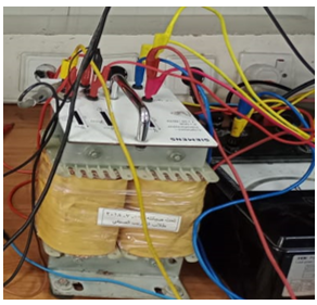
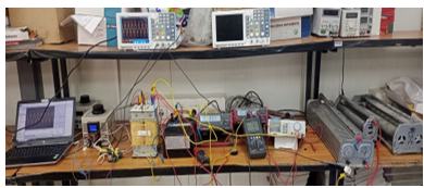
A 1 KVA single-phase transformer, 220 volts, and a frequency of 50Hz was used in this work as shown in Figure 1. Important details regarding a single-phase transformer's core losses, signature current, no-load losses, and voltage regulation can be obtained from the test conducted without any load. This data is crucial for quality control during manufacture as well as for evaluating the transformer's functionality and suitability for various applications. The practical tests have been done in the laboratories of the Department of Electrical Engineering-University of Mosul-Iraq as shown in Figure 2.
Figure 1. KVA single-phase transformer
Figure 2. Experimental test of a KVA single-phase transformer
To assess a single-phase transformer's performance under linear load conditions, a load test is necessary. It assists in calculating voltage regulation, measuring copper losses, estimating load losses, confirming rated current and voltage handling capabilities, and evaluating a range of performance attributes. To make sure the transformer fits its intended uses and quality standards, this information is essential.
Table 1 shows the transformer used in this work. The transformer was subjected to working within the manufacturing standards to conduct a no-load test and a full load test to obtain all ratings and parameters of the transformer.
Several linear and non-linear loads were applied to increase the current supplied by the transformer, voltage, current, and harmonic were measured, as well as the shape of current curve, were recorded and monitored.
Table 1. Parameters of single-phase transformer
|
Parameter |
Value |
Unit |
|
Rated power |
1 |
KVA |
|
Voltage |
220/110 |
Volt |
|
Current |
4.55/9.1 |
Amber |
|
Frequency |
50 |
Hz |
|
Turn ration |
1/2 |
----- |
The results of this work have categories into numerous groups to highlight the important points which benefit of this work. First group of the results depending on feed the transformer from sinusoidal power supply and the load is linear. This load is resistance connected to the secondary of transformer windings. Figure 2 displayed the full load of single-phase transformer resistive load.
4.1 Feed transformer from a sinusoidal source and the load is linear
Initially, the single-phase electrical transformer was operated from a sinusoidal source. Figure 3 shows the voltage load when the load on the transformer 50% from the full load. Figure 4 appears the current wave on the linear load.
Table 2 illustrates there is a small distortion 3.4% of the voltage and current. Through laboratory tests and when the transformer is operated at a resistive load close to full load. It was found that the transformer was operating at an efficiency of up to 88%, and losses reached up to 120 watts. Since the loads are linear, the transformer still operates within the limits of the magnetization curve on the linear region.
Figure 3. Voltage load when the load on the transformer 50% from the full load
Figure 4. Current wave on the linear load
Table 2. Input and output currents of transformer in the linear loads
|
Iin (A) |
Iout (A) |
Pout (W) |
THD-V (%) |
THD-I (%) |
|
5.3 |
2.68 |
520 |
3.3 |
3.3 |
|
6 |
2.95 |
680 |
3.3 |
3.3 |
|
7 |
3.43 |
760 |
3.4 |
3.4 |
|
8 |
3.96 |
880 |
3.4 |
3.4 |
While the load is resistive, the voltage and current load in the same phase, so there is no phase shift between the voltage and current. Figure 5 display the waves of voltage and current in the resistive which are measure using the oscilloscope.
Figure 5. Input current (5.3 A) with resistive load
4.2 Feed transformer from a sinusoidal source and the load is non-linear
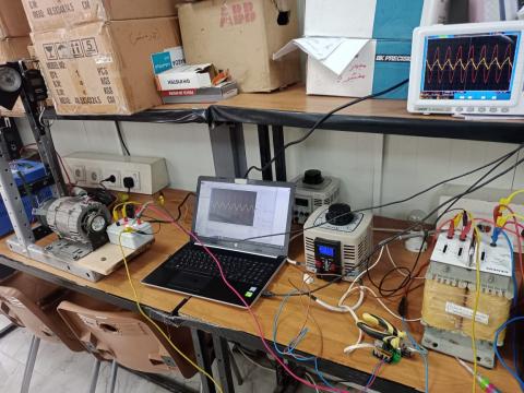
Second group of the results, the transformer feed from sinusoidal power supply and the load is non-linear. The non-linear load applied here as a single-phase induction motor. Figure 6 shown the experimental work in the lap to highlight the effect of non-liner load to the performance of transformer. A non-sinusoidal supply, which is typified by abnormalities and harmonics in the waveform, can affect a transformer's performance in a number of ways:
Figure 6. Non-linear load with linear power supply
In the transformer, non-sinusoidal waveforms may result in increased copper and core losses. This is because the non-sinusoidal current waveform increases resistance losses in the windings from harmonic currents and adds to eddy current and hysteresis losses in the core.
The transformer's temperature may rise more due to the larger losses brought on by non-sinusoidal waveforms. In the event that the temperature rises above acceptable operating limits, this may result in decreased efficiency, faster aging of the insulation materials, and possibly a shorter lifespan. The output of the transformer may experience voltage distortion from a non-sinusoidal supply. Voltage spikes, dips, or fluctuations may be the result of this distortion, which can impair linked equipment's functionality and cause problems like malfunctions or equipment damage. Poor power quality is typified by voltage and current harmonics, voltage imbalance, and waveform distortion, all of which can be caused by non-sinusoidal waveforms.
Several mechanical loads were applied to the single-phase induction motor to increase the current drawn from the transformer. This, explains the effect of this type of non-linear load on the properties of the transformer. Table 3 provides the values of THD to the voltage and current in the different values of the non-linear loads.
Table 3 shows an increase in distortion values in both of voltage and current waves. The THD of current reached several times what it was compared to a linear load. The table also shows that when the load increases, the THD current improves, meaning it decreases. This result is consistent with increasing the load on the single-phase induction motor, the THD of the current decreases and the properties improve. It was found that the transformer was operating at an efficiency of up to 84%, and losses reached up to 160 watts. That is means the losses increased 25% as compared with the first case. Since the loads are non-linear, the transformer start operates to move away from linear region of the magnetic curve due to the increase in harmonics, which reached 6.4%. Figure 7 shown the voltage and current waves, and it is clearly appeared the current distortion is higher than voltage.
Table 3. Input and output currents of transformer in the non-linear loads
|
Iin (A) |
Iout (A) |
Pout (W) |
THD-V (%) |
THD-I (%) |
|
3.7 |
1.66 |
350 |
3.8 |
18.7 |
|
4.5 |
2.1 |
470 |
3.7 |
13 |
|
5.3 |
2.56 |
580 |
3.8 |
9.3 |
|
6 |
2.87 |
630 |
3.9 |
10 |
|
8 |
4 |
840 |
3.3 |
6.4 |
Figure 7. Voltage and current waves of non-linear load with linear power supply
All the tests, were measured and recorded by transfer the signals form the channels in the oscilloscope to the PC to get the data of these waves as shown in Figure 8.
Figure 8. Experimental test of linear power supply with non-linear load (induction motor)
At the transformer's output, harmonic currents drawn by non-linear loads may distort the voltage. The quality of power given to connected equipment can be impacted by this distortion, which might appear as voltage spikes, dips, or waveform distortion. Problems include equipment failure, overheating, and decreased operational dependability can result from voltage distortion. The transformer's internal temperature may rise as a result of the increased losses brought on by harmonic currents. This may result in shorter insulation life, faster aging of the insulation materials, and possibly even thermal stress on the transformer's internal parts.
Transformer performance is greatly impacted by harmonic distortion, which is mostly brought on by non-linear loads like rectifiers, variable frequency drives (VFDs), and other power electronic devices. Current and voltage waveform distortions are caused by harmonics, which are integer multiples of the fundamental frequency produced by these loads. Because harmonics have higher frequencies, they cause additional heating by increasing both core (eddy current and hysteresis) and copper (I²R) losses. The transformer may overheat as a result of this high heating, shortening its lifespan and raising the possibility of insulation failure. In order to ensure that transformers function within safe temperature limits, it might be necessary to de-rate them in order to accommodate the higher thermal load.
The electrical system is exposed to harmonics when a non-sinusoidal power supply is used. Reduced transformer efficiency, increased core losses, saturation effects, and voltage distortion can result from these harmonics' distortion of the voltage and current waveforms. The transformer may overheat and have a shorter lifespan as a result of the B-H curve distortion and higher core losses.
4.3 Feed transformer from non-sinusoidal source and the load is linear
The third groups of the results which getting from using non-sinusoidal power supply to feed the transformer and the load is linear. Figure 9 shown the voltage wave of this type of non-sinusoidal power supply.
Due to the obvious distortion in the voltage waveform of this type of source, this will be directly reflected in the performance of the transformer in terms of current drawn, losses and THD. Table 4 demonstrates the test which has been done when the load is linear and power supply non-linear. It is notes that the THD of the voltage and current are close together because there is no phase shift between them.
Figure 9. Voltage wave of non-sinusoidal power supply
Table 4. Results when the load is linear and power supply non-linear
|
Iin (A) |
Iout (A) |
Pout (W) |
THD-V (%) |
THD-I (%) |
|
6 |
3 |
650 |
8.3 |
7.7 |
|
7 |
3.44 |
740 |
8.3 |
7.7 |
|
8 |
3.9 |
860 |
7.7 |
7.7 |
Elevated THD levels may cause the transformer to produce more heat. Due to the degradation of insulation materials and shortened transformer lifespan caused by extreme heat, this could be harmful to the transformer's overall performance and efficiency. THD may result in output voltage distortion from the transformer. This distortion may result in problems like voltage spikes or fluctuations, which could affect the functionality of systems or equipment that are connected. Increased core losses and copper losses in the transformer may be the result of higher THD levels. Due to the increased energy consumption, this may lower the transformer's overall efficiency and raise running expenses. Increased electromagnetic interference (EMI) and noise in the electrical system can also be caused by high THD levels. This interference can cause signal degradation in communication networks and interfere with the operation of adjacent equipment.
But, when compare the results between Table 2 with 4 it is appeared the THD of voltage and current increased to double 7.7% in spite of the load is linear. The reason for this is that the source played a major role in this increase when it was linear and became non-linear. Figure 10 shows the voltage and current waves in this case of results. In this case, a non-sinusoidal source was used, which is a source that contains power electronics circuits that are known to lead to distortions in the output waveform.
Figure 10. Voltage and current waves in this case of non-sinusoidal power supply with linear load
It was found that the transformer was operating at an efficiency of up to 86%, and losses reached up to 140 watts. That is means the losses increased 16% as compared with the first case. Harmonic distortion is caused by non-linear loads drawing non-sinusoidal currents from the power supply. In addition, these harmonics have the potential to cause voltage distortion, saturation effects, increased core losses, and B-H curve distortion. Non-linear loads have the potential to greatly increase the system's overall harmonic content, which can affect the transformer and other associated devices.
Transformer performance is greatly impacted by non-sinusoidal currents, which are normally drawn by non-linear loads such as power electronic devices. The transformer and the power system as a whole operate less efficiently as a result of these currents' deviation from the ideal sine wave, which raises reactive power and lowers the power factor. Non-sinusoidal currents can lead to distortion of the voltage waveform, which can adversely affect other connected equipment and result in malfunctions or decreased efficiency. Careful management and mitigation techniques are required since the cumulative effect of these non-sinusoidal currents can result in greater operating expenses and increased strain on the electrical infrastructure.
4.4 Feed transformer from non-sinusoidal source and the load is non-linear
In the last groups on these results were getting from non-sinusoidal power supply with non-linear load. Table 5 presents the results when the power supply and load are non-linear. The main purpose of taking this type of sources with this type of loads is to demonstrate the effect of these sources on the operation of the transformer and its characteristics.
Table 5. Results when the power supply and load are non-linear
|
Iin (A) |
Iout (A) |
Pout (W) |
THD-V (%) |
THD-I (%) |
|
3.7 |
1.74 |
300 |
7.5 |
64 |
|
4.5 |
2 |
360 |
7.8 |
55.6 |
|
5.3 |
2.55 |
570 |
5.4 |
21.6 |
|
6 |
2.93 |
630 |
5.6 |
18.4 |
|
8 |
3.87 |
800 |
6 |
12.4 |
Several readings and different values of non-linear loads were taken to monitor the operation of the transformer when these loads on the transformer were changed. At light loads, a significant increase in distortion of both voltage and current waves is observed. However, as the loads increase, this THD decreases to a lower level than it was, but the TDH 12.4% consider higher as compared to the first cases that were taken in this work. It was found that the transformer was operating at an efficiency of up to 80%, and losses reached up to 200 watts. Figure 11 and 12 shown the voltage and current of this case light and 90% loads respectively when the transformer feed from non-sinusoidal power supply with light of non-linear load.
The B-H curve of a transformer, which illustrates the relationship between the magnetic flux density (B) and the magnetic field strength (H) in the core material of the transformer, can be significantly impacted by non-sinusoidal power supplies and non-linear loads. Distortion of B-H Curve, Increased Core Losses, Saturation Effects, Voltage Distortion and Increased Harmonic Content all these issues were reflected with transformer performances. The rated capacity and overall performance of the transformer may also be impacted by an excessive temperature rise. When compared to linear loads, non-linear loads frequently have a lower power factor.
Figure 11. Voltage and current of this case light load
Figure 12. Voltage and current of this case 90% full load
This may cause the transformer's apparent power factor to drop, which would raise apparent power and increase energy losses. These problems may get worse if power factor adjustment is done inefficiently. Voltage and current fluctuations brought on by non-linear loads have the potential to overload the transformer. The transformer's rated capacity may be exceeded by abrupt increases in load demand or transient events brought on by non-linear loads, which could result in overheating, insulation failure, and even failure.
Non-linear loads and non-sinusoidal power supplies can both cause various kinds of distortion and stress on the transformer's components, which can be detrimental to the device. The negative impacts of non-sinusoidal power supplies and non-linear loads on transformers can be lessened with the use of mitigation techniques including harmonic filters, appropriate transformer sizing, and clean power quality maintenance.
4.5 The implications of the increased losses and THD on transformer performance and lifespan
Transformers suffer increased losses, which are divided into two categories: core (eddy current and hysteresis) losses and copper (I²R) losses when non-linear loads produce harmonic currents. Since copper losses are closely correlated with the square of the current, even slight increases in harmonic currents can have a major impact on total losses and increase the amount of heat generated within transformer windings. Higher frequency magnetic flux changes brought on by harmonic currents result in an increase in core losses. Higher-order harmonics in particular are harmful because eddy current losses, in particular, are proportional to the square of the frequency. Elevated operating temperatures as a result of the cumulative rise in losses can cause the insulating materials to deteriorate more quickly and fail before their time.
Transformer overheating, which hastens the aging process of insulation and increases the danger of insulation failure, is the main effect of higher losses. More cooling systems are needed when there is overheating, which increases operating expenses. Another significant effect is reduced efficiency; as more energy is lost as heat as a result of higher losses, the transformer's efficiency is reduced and the cost of delivering power is raised. To handle the increased heat dissipation, operators are forced by this inefficiency to de-rate transformers, running them below their rated capacity. De-rating essentially lowers the load capacity of the transformer, requiring the construction of additional transformers to carry the same load, which raises operating complexity and capital costs.
Significant harmonic present, which alters the voltage and current waveforms, is indicated by high THD levels. Harmonic current-induced voltage distortion can impair delicate electronic devices, leading to malfunctions, decreased efficiency, or even irreversible harm. Further distortion of the voltage waveform is caused by voltage dips across the transformer's impedance, which is also caused by the harmonic currents. In addition, the transformer windings and core experience mechanical strains and vibrations due to harmonic currents. These mechanical strains have the potential to cause physical deterioration over time, such as loosening of windings and core vibrations, which can raise noise levels and even cause mechanical failure. The transformer's operational lifespan is shortened by the combined effect of mechanical and thermal stresses, which raises the cost of lifecycle maintenance or replacements.
4.6 The scalability of the results to larger transformers and different power system configurations
The effects of non-sinusoidal currents and harmonic distortion increase proportionately with transformer size and vary depending on the layout of the power system. High-power applications involving larger transformers have problems comparable to those of smaller ones, including higher losses and overheating from harmonic currents. To manage the extra heat, larger transformers usually use more sophisticated cooling systems (such as forced air or oil cooling), which may lessen some negative impacts. However, the underlying problems still exist: hysteresis losses and harmonic-induced eddy current lead to reduced efficiency and faster aging, requiring careful thermal control and maybe de-rating to guarantee dependable operation.
Non-linear demands can vary greatly in various power system topologies, such as those with dispersed generation or renewable energy sources. The harmonic content can be significant in systems with a large penetration of power electronic equipment (such as wind turbines or solar PV inverters), which exacerbates the effect on transformer performance. Systems with higher proportions of linear loads might be less troublesome, but the detrimental impacts on transformers increase with the incorporation of non-linear loads. Maintaining system dependability and transformer longevity across different scales and configurations requires managing harmonics through filters, appropriate transformer sizing, and strategic de-rating, regardless of the particular design.
The conclusions of this paper can be of particular use to experts, researchers, and engineers involved in power system design, operation, and maintenance, particularly in the context of single-phase transformers and non-sinusoidal condition. Non-sinusoidal supplies can negatively impact transformer performance by raising the temperature, causing losses, distorting voltage, and lowering efficiency and power quality overall. In this work, an experimental setup of a single-phase transformer has been done. According to the investigation's findings, when a transformer is fed from a non-sinusoidal power source and non-linear loads as opposed to a sinusoidal and linear load, losses rise by 40% and THD by 12.4%. Higher-order harmonics in the magnetic flux result from non-linear loads drawing harmonic currents. Additional hysteresis losses may result from these higher harmonics' ability to enlarge the hysteresis loop's area. Transformer performance is greatly impacted by non-linear loads because they increase losses, lead to overheating, warp voltage waveforms, and create mechanical strains. To ensure dependable and effective operation, mitigating these impacts necessitates a mix of optimal system configuration, harmonic filtering, and transformer design.
The authors would like to thank University of Mosul, College of Engineering, Electrical Department, for the support given during this work.
[1] Alyozbaky, O.S. (2018). The losses and temperature comparison in three-phase distribution transformer with various assembly core designs. Australian Journal of Electrical and Electronics Engineering, 15(3), 61-70. https://doi.org/10.1080/1448837X.2018.1522793
[2] Balci, S. (2020). Thermal behavior of a three phase isolation transformer under load conditions with the finite element analysis. Thermal Science, 24(38): 2189-2201. https://doi.org/10.2298/TSCI190706386B
[3] Biricik, S., Özerdem, Ö.C. (2011a). A method for power losses evaluation in single phase transformers under linear and nonlinear load conditions. Przeglad Elektrotechniczny, 87(12 A): 74-77.
[4] Biricik, S., Özerdem, Ö.C. (2011). Experimental study and comparative analysis of transformer harmonic behaviour under linear and nonlinear load conditions. In 2011 10th International Conference on Environment and Electrical Engineering, Rome, Italy, pp. 1-4. https://doi.org/10.1109/EEEIC.2011.5874818
[5] Cataliotti, A., Cosentino, V., Crotti, G., Giordano, D., Modarres, M., Di Cara, D., Tinè G, Gallo D, Landi C, Luiso, M. (2018). Metrological performances of voltage and current instrument transformers in harmonics measurements. In 2018 IEEE International Instrumentation and Measurement Technology Conference (I2MTC), Houston, TX, USA, pp. 1-6. https://doi.org/10.1109/I2MTC.2018.8409694
[6] Cazacu, E., Petrescu, M.C., Ioniţă, V., Petrescu, L. (2018). Nonsinusoidal load current effect on the electrical and thermal operating parameters of oil filled power distribution transformers. In 2018 18th International Conference on Harmonics and Quality of Power (ICHQP), Ljubljana, Slovenia, pp. 1-6. https://doi.org/10.1109/ICHQP.2018.8378838
[7] Cieślik, S., Boniewicz, P. (2015). The impact of initial phases of higher harmonics of the supply voltage of a single-phase transformer on the power losses in its core. In 2015 9th International Conference on Compatibility and Power Electronics (CPE), Costa da Caparica, Portugal, pp. 144-150. https://doi.org/10.1109/CPE.2015.7231063
[8] Chen, D., Fang, L., Kwon, B.I., Bai, B. (2017). Measurement research on magnetic properties of electrical sheet steel under different temperature, harmonic and DC bias. AIP Advances, 7(5): 056682. https://doi.org/10.1063/1.4979490
[9] Chen, D., Feng, Z., Bai, B., Kwon, B.I. (2019). Study of transformer magnetic field considering different temperature and DC bias of electrical steel sheet. International Journal of Applied Electromagnetics and Mechanics, 59(2): 669-677. https://doi.org/10.3233/JAE-171137
[10] Lopera-Mazo, E.H., Londoño-Parra, C.M. (2019). Experimental magnetization curve of a transformer considering harmonic distortion. In 2019 IEEE Workshop on Power Electronics and Power Quality Applications (PEPQA), Manizales, Colombia, pp. 1-6. https://doi.org/10.1109/PEPQA.2019.8851565
[11] Lesniewska, E., Kaczmarek, M., Stano, E. (2020). 3D electromagnetic field analysis applied to evaluate the accuracy of a voltage transformer under distorted voltage. Energies, 14(1): 136. https://doi.org/10.3390/en14010136
[12] Ertl, M., Voss, S. (2014). The role of load harmonics in audible noise of electrical transformers. Journal of Sound and Vibration, 333(8): 2253-2270. https://doi.org/10.1016/j.jsv.2013.12.022
[13] Fakhrian, A., Ganji, B., Mohammadi, H.R., Samet, H. (2019). De-rating of transformers under non-sinusoidal loads: Modeling and analysis. In 2019 IEEE International Conference on Environment and Electrical Engineering and 2019 IEEE Industrial and Commercial Power Systems Europe (EEEIC/I&CPS Europe), Genova, Italy, pp. 1-5. https://doi.org/10.1109/EEEIC.2019.8783508
[14] Durante, L., Nielsen, M., Ghosh, P. (2017). Analysis of non-sinusoidal wave generation during electric vehicle charging and their impacts on the power system. International Journal of Process Systems Engineering, 4(2-3): 138-150. https://doi.org/10.1504/IJPSE.2017.084751
[15] Godina, R., Rodrigues, E.M., Matias, J.C., Catalão, J.P. (2015). Effect of loads and other key factors on oil-transformer ageing: Sustainability benefits and challenges. Energies, 8(10): 12147-12186. https://doi.org/10.3390/en81012147
[16] Gupta, A., Singh, R. (2011). Computation of transformer losses under the effects of nonsinusoidal currents. Advanced Computing, An International Journal (ACIJ), 2(6): 91-104. https://doi.org/10.5121/acij.2011.2609
[17] Kim, J., Lai, J.S. (2019). Analysis of a shunt wye–delta transformer for multi-generator harmonic elimination under non-ideal phase-shift conditions. IEEE Transactions on Industry Applications, 55(3): 2412-2420. https://doi.org/10.1109/TIA.2019.2897319
[18] Kovernikova, L., Van Cuong, N. (2018). Evaluation of the influence of non-sinusoidal conditions on power transformers. In E3S Web of Conferences. EDP Sciences, 58: 03012. https://doi.org/10.1051/e3sconf/20185803012
[19] Liu, Y., Sun, C., Yang, X., Jia, Z., Su, J., Guo, Z. (2024). A transformer heavy overload spatiotemporal distribution prediction ensemble under imbalanced and nonlinear data scenarios. Sustainability, 16(8): 3110. https://doi.org/10.3390/su16083110
[20] Masoum, M.A.S., Moses, P.S., Deilami, S. (2010). Load management in smart grids considering harmonic distortion and transformer derating. In 2010 Innovative Smart Grid Technologies (ISGT), Gaithersburg, MD, USA, pp. 1-7. https://doi.org/10.1109/ISGT.2010.5434738
[21] Mirzaie, M., Yazdani-Asrami, M., Sadati, S.B., Akmal, A.S. (2011). Impacts of non-sinusoidal load currents on distribution transformer losses-Part II: Standard aspects and experimental measurement. International Review of Electrical Engineering (IREE) Journal, 6(5): 2215-2220.
[22] Montoya, F.G., Baños, R., Alcayde, A., Arrabal-Campos, F.M. (2020). A new approach to single-phase systems under sinusoidal and non-sinusoidal supply using geometric algebra. Electric Power Systems Research, 189: 106605. https://doi.org/10.1016/j.epsr.2020.106605
[23] Ngo, X.C., Do, N.Y. (2021). Influence of harmonics on the working efficiency of a 6/1.2kV transformer in a pit mine. Journal of the Polish Mineral Engineering Society, 1(2): 149-156. http://doi.org/10.29227/IM-2021-02-
[24] Iacobici, N.L., Cazacu, E., Frigura-Iliasa, M., Frigura-Iliasa, F.M. (2019). Computer based analysis for the parameters of a distribution transformer in a non-sinusoidal regime. In 2019 IEEE 17th World Symposium on Applied Machine Intelligence and Informatics (SAMI), Herlany, Slovakia, pp. 371-374. https://doi.org/10.1109/SAMI.2019.8782753
[25] Pratama, N.A., Rahmawati, Y. (2020). Evaluation of unbalanced load impacts on distribution transformer performances. Frontier Energy System and Power Engineering, 2: 28-35. http://dx.doi.org/10.17977/um048v2i1p28-35
[26] Said, D.M., Nor, K.M., Majid, M.S. (2010). Analysis of distribution transformer losses and life expectancy using measured harmonic data. In Proceedings of 14th International Conference on Harmonics and Quality of Power-ICHQP 2010, Bergamo, Italy, pp. 1-6. https://doi.org/10.1109/ICHQP.2010.5625404
[27] Deokar, S.A., Waghmare, L.M. (2011). Impact of power system harmonics on insulation failure of distribution transformer and its remedial measures. In 2011 3rd International Conference on Electronics Computer Technology, Kanyakumari, India, pp. 136-140. https://doi.org/10.1109/ICECTECH.2011.5941817
[28] Shareghi, M., Phung, B.T., Naderi, M.S., Blackburn, T.R., Ambikairajah, E. (2012). Effects of current and voltage harmonics on distribution transformer losses. In 2012 IEEE International Conference on Condition Monitoring and Diagnosis, Bali, Indonesia, pp. 633-636. https://doi.org/10.1109/CMD.2012.6416225
[29] Yang, S., Zhou, G., Wei, Z. (2018). Influence of high voltage DC transmission on measuring accuracy of current transformers. IEEE Access, 6: 72629-72634. https://doi.org/10.1109/ACCESS.2018.2874624
[30] Singh, R., Singh, A. (2010). Aging of distribution transformers due to harmonics. In Proceedings of 14th International Conference on Harmonics and Quality of Power-ICHQP 2010, Bergamo, Italy, pp. 1-8. https://doi.org/10.1109/ICHQP.2010.5625347
[31] Chen, X., Yang, N., Y.Y. (2021). Comparison of low‑frequency non‑sinusoidal measurement for transformer no‑load characteristics based on different interpolation methods. Electrical Engineering, 103: 1807-1821.
[32] Özüpak, Y., Mamiş, M.S. (2020). Analysis of electromagnetic and loss effects of sub-harmonics on transformers by Finite Element Method. Sādhanā, 45(1): 226. https://doi.org/10.1007/s12046-020-01473-4
[33] Zhang, P., Li, L. (2020). Vibration and noise characteristics of high-frequency amorphous transformer under sinusoidal and non-sinusoidal voltage excitation. International Journal of Electrical Power & Energy Systems, 123: 106298. https://doi.org/10.1016/j.ijepes.2020.106298