Hoang Bui Huu![]() | Viet Nguyen Nga
| Viet Nguyen Nga![]() | Dinh Bui Minh
| Dinh Bui Minh![]() | Bao Doan Thanh
| Bao Doan Thanh![]() | Vuong Dang Quoc*
| Vuong Dang Quoc*![]()
© 2024 The authors. This article is published by IIETA and is licensed under the CC BY 4.0 license (http://creativecommons.org/licenses/by/4.0/).
OPEN ACCESS
In this study, a surface mounted-permanent magnet synchronous motor (SPMSM) with outer rotor configuration applied to the fields of industry and electric drive is proposed by an association between the analytical model and finite element technique. Firstly, the methodology involves a detailed development of the analytical calculation to compute crucial parameters for the SPMSM. Next, a finite element technique is proposed to validate the analytical parameters and simulate various aspects such as the magnetic flux density, output torque, cogging torque, torque ripple, back electromotive force, flux linkage and temperature rise. The developed methods are tested and validated on a practical problem involving a 7.5kW SPMSM with outer rotor type.
surface-mounted-permanent magnet synchronous motor, outer rotor configuration, analytical method, finite element technique
Over the decades, the world has confronted various environmental challenges, notably global warming and air pollution. One significant contributor to air pollution is the use of fossil fuels in vehicles, emitting harmful gases. Beyond environmental concerns, issues like traffic congestion and soaring oil prices have prompted nations to explore alternative, eco-friendly transportation modes, with electric vehicles (EVs) emerging as a viable solution. Among the spectrum of EVs, the electric bicycle stands out as a suitable option for short-distance travel due to its attractive attributes such as affordability, ease of riding, convenient parking, health benefits, and environmental friendliness [1-4]. The motor for EVs plays a pivotal role, demanding careful design to ensure high efficiency, torque, and minimal noise.
In recent years, designers and researchers have scrutinized various motor types to identify the most efficient ones for powering EVs. Commonly employed motors for such applications include the switched reluctance motor (SRM), permanent magnet flux-switched motor (PMFSM), multi-flux permanent magnet (MFPM), permanent magnet synchronous motor (PMSM) and synchronous reluctance motor (SynRM) [5-10]. These motors have some advantages such as compact size and light weight due to the absence of brushes in their design. The rotor design of EV motors typically falls into two categories: those with an outer rotor, fitting between the two cranks and chain wheel, and those with an outer rotor, fitting into the wheel. Manh et al. [5] proposed various permanent magnet layouts in the rotor of the line-start permanent magnet assistance synchronous reluctance motor to mitigate this drawback. The finite element method is used to study the V magnet form while accounting for skewed slots, demagnetization effect, and short circuit current. Feng et al. [6] primarily examined how the air-gap flux density, cogging torque, back electromagnetic force (EMF), and stator loss are affected by the rotor's dynamic eccentricity. It has a specific reference value for researching the low-speed high-torque PMSM rotor eccentricity. Lin et al. [7] proposed a 3-phase, external-rotor SRM that is intended for use in e-bike applications. It features 10 rotor poles and 6 stator poles. The bicycle kinematics are evaluated before beginning the SRM design and simulation. The machine's major dimensions and output power equation are determined analytically, and then a thorough finite element analysis (FEA) is conducted. In the study [8], the design of an electric bicycle axial-field permanent magnet (PM) brushless DC motor drive was presented. There are specifications for both the electronic converter and the motor. A brief discussion of the FEA was given for performance analysis. To confirm the real performance, a prototype motor was built. A strong correlation has been observed between the theoretical and experimental outcomes. Test findings verified that the suggested motor design was feasible. Huang [9] reviewed and compared various types of PM machines, including single and multiple rotor PM machines, radial, axial, and transverse flux PM machines, concentrated and distributed PM machines, electrically excited synchronous machines and reluctance machines, and exterior and interior rotor PM machines. Jung et al. [10] offered a comparative analysis of the features of bar-type interior PMSM and surface-mounted PMSM (SPMSM). The identical stator shape, rated speed, number of turns, winding parameters, voltage limit, and magnet usage are configured in a pole/slot combination of six poles and 27 slots in order to perform characteristic analysis. Jusoh et al. [11], compared the inner and outer rotor designs of a single-phase PM flux switching machine with 8S-10P that was created especially for an electric bicycle. Using 2D-FEA, the machine performance was verified. The obtained result showed that the torque of the outer rotor is roughly 54.2% that of the inner rotor PMFSM.
Although many authors have researched the PMSMs as analyzed above. However, detailing the analytical calculation process to determine the required parameters of a synchronous motor is still a challenge that not many authors have mentioned.
In this paper, the required parameters of the SPMSM with outer rotor configuration as illustrated in Figure 1 is first designed by an analytical approach. Then, the FEA is presented to verify output parameters and simulate the magnetic flux density, torque, cogging torque, torque ripple, back EMF, flux linkage and temperature rise. The development of these methods will be validated on a 7.5kW SPMSM with outer rotor sturcture.
Figure 1. SPMSM with outer-rotor configuration
In this section, it provides a detailed presentation of the analytical design for the SPMSM with outer rotor type. The input parameters for this machine are given in Table 1.
Table 1. Input parameters of SPMSM with outer rotor configuration
|
No. |
Description |
Value |
Unit |
|
1 |
Input power (Prated) |
7,5 |
kW |
|
2 |
Rated voltage (Urated) |
380 |
V |
|
3 |
Efficiency ($\eta$) |
93 |
% |
|
4 |
Frequency ($f_{\text {rated }}$) |
50 |
Hz |
|
5 |
Power factor (cosφ) |
0.9 |
0.9 |
|
6 |
Number of pole pairs (p) |
4 |
pairs |
|
7 |
Phase number (m) |
3 |
phase |
|
8 |
Speed of rotor (n) |
750 |
rpm |
2.1 Design of stator
The outer diameter of stator is defined via the inner diameter of rotor $\left(D_{i r}\right)$, air gap thickness $(g)$ and the PM thickness $\left(d_m\right)$, i.e., [9, 10, 12]:
$D_{o s}=D_{i r}-2\left(g+d_m\right)$, (1)
The parameter $D_{i r}$ is determined as [9, 12]:
$D_{\text {ir }}=\left(\frac{V_r \cdot 4}{\pi \cdot k_{\text {shape }}}\right)^{\frac{1}{3}}, V_r=\frac{0.5 \cdot M_{\text {rated }} \cdot k_{\text {safe }}}{\sigma_m}$, (2)
where, $V_r$ is the volume of stator and $k_{\text {shape }}$ is the shape factor $\left(k_{\text {safe }}=2-3\right)$ [9], $\sigma_m$ is the maximum stress and $M_{\text {rated }}$ is the rated torque.
The PM thickness $\left(d_m\right)$ is computed via the following parameters [12]:
$d_m=\frac{\mu_r g}{\frac{B_r}{B_{g 0}}-1}$, (3)
where, $\mu_r$ is the relative permeability of $\mathrm{PM}, B_r$ is the remenant PM and $B_{g 0}$ is the magnetic flux density at the air gap. The stator length $\left(L_{\text {act }}\right)$ is defined as:
$L_{\text {act }}=\frac{D_{\text {ir }}}{k_{\text {shape }}}$. (4)
Via the term $D_{i r}$ given in the Eq. (2), the width of each PM pole $\left(w_p\right)$ is defined as:
$w_p=\frac{D_{i r} \cdot \pi}{p}$. (5)
The width of PM $\left(w_m\right)$ is calculated via the electrical angle of the $\mathrm{PM}(\alpha)$, i.e.,
$w_m=\frac{2 \alpha \cdot w_p}{\pi}$ (6)
Finally, the magnetic flux $\left(\phi_m\right)$ of the PM is defined as:
$\phi_m=B_m \cdot w_m \cdot L_{a c t}$ (7)
The magnetic flux on the tooth $\left(\phi_t\right)$ and the width of tooth $\left(w_t\right)$ are respectively defined as:
$\phi_t=\frac{\phi_m \cdot 2 \mathrm{p}}{Q} ; w_t=\frac{\phi_t}{L_{\text {act }} \cdot k_{\text {stack }} \cdot B_t}$ (8)
where, Q is the number of slots, $k_{\text {stack }}$ is the pressed factor of the stator yoke. The large diameter $\left(b_1\right)$ and small diameter $\left(b_2\right)$ of stator are calculated as:
$b_1=\frac{\pi \times\left(D_{o s}-2\left(h_w+h_{s 0}\right)\right.}{Q}-w_t$, (9)
$b_2=\sqrt{\frac{b_1{ }^2-4 \pi \times A_{\text {slot }}}{Q}}$, (10)
where, $A_{\text {slot }}$ is the slot area. The height of stator slot is finally defined via the $b_1$ and $b_2$.
$h_s=\frac{2 A_{\text {slot }}}{b_1+b_2}$ (11)
2.2 Design of outer rotor structure
In convention, the lengths of rotor yoke $\left(L_{r y}\right)$ and staor yoke $\left(L_{r y}\right)$ are defined as [9-12]:
$L_{r y}=\frac{B_m \times w_m}{2 B_{r y}} ; L_{s y}=\frac{B_m \times w_m}{2 B_{s y}}$ (12)
where, $B_{r y}$ and $B_{s y}$ are the magnetic fluxes on the rotor and stator teeth, respectively. Finally, the outer diameter of the rotor is determined via the inner diameter and rotor length:
$D_{o r}=D_{i r}+L_{r y}$ (13)
2.3 Design of windings
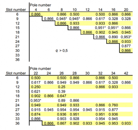
The winding factor $\left(k_{d q}\right)$ is chosen following to Figure 2. The area of the winding $\left(S_d\right)$ is calculated as [9]:
$S_d=\frac{I_p}{J \cdot a}$ and $d=\sqrt{\frac{4 \cdot S_a}{\pi \cdot b}}$ (14)
where, $I_p$ is the phase current, $J$ is the electric current density and $a$ is the number of parallel branches. The number of turns is then calculated as:
$n_s=\frac{1,1 \cdot U_p}{2 \sqrt{2} \cdot \pi \cdot f_s \cdot q \cdot k_{d q} \cdot B_g \cdot \cos \gamma \cdot D_{i r} \cdot L_{a c t}}$, (15)
where, $\gamma$ is the torque angle and $k_{d q}$ is the winding factor.
Figure 2. Winding factor ($k_{d q}$) [9]
The diagram of stator windings and cross-section of the motor is pointed out in Figure 3. Based on the development of the analytical theory, the results are given in Table 2.
Figure 3. Diagram of stator windings (top) and cross-section of the motor (bottom)
Table 2. Analytical results
|
Description |
Value |
Unit |
|
Outer diameter of stator |
171 |
mm |
|
Inner diameter of stator |
73.5 |
mm |
|
Outer diameter of rotor |
212.95 |
mm |
|
Inner diameter of rotor |
178 |
mm |
|
Length of stator |
178 |
mm |
|
Number of stator slots |
10 |
Rãnh |
|
Air gap |
1 |
mm |
|
Thickness of PM |
2.5 |
mm |
|
Efficiency |
94.016 |
% |
|
Torque |
95.839 |
Nm |
|
Power factor |
0.943 |
|
|
Output Power |
7527.2 |
W |
|
Total Losses (on load) |
479.12 |
W |
In this part, the FEA is developed to verify main parameters obtained from the analytical model as presented in Section II. The Maxwell’s equations and constitutive laws are expressed in Euclidean space $\mathbb{R}^3$ [9, 13-19]:
$\operatorname{rot} \mathrm{H}=\mathrm{J}_s, \quad \operatorname{rot} \mathrm{E}=-j \omega \mathrm{B}, \quad \operatorname{div} \mathrm{B}=0$, (16)
$\mathrm{B}=\mu \mathrm{H}, \quad \mathrm{J}=\sigma \mathrm{E}$, (17)
where, $\mathrm{J}_s$ is the current density $\left(\mathrm{A} / \mathrm{m}^2\right), \mathrm{H}$ is the magnetic field $(\mathrm{A} / \mathrm{m}), E$ is the electric field $(\mathrm{V} / \mathrm{m}), B$ is magnetic flux density (T), J is the eddy current density $\left(\mathrm{A} / \mathrm{m}^2\right), \mu$ and $\sigma$ are respectively the relative permeability and electric conductivity ( $\mathrm{S} / \mathrm{m}$ ) and $n$ is the unit normal exterior to $\Omega$ (with $\Omega=\Omega_c \cup$ $\left.\Omega_C^c\right$).
The above Eq. (17) is solved with boundary conditions (BCs) [9]:
$n \times\left.\mathrm{H}\right|_{\Gamma_h}=0,\left.\quad n \cdot \mathrm{B}\right|_{\Gamma_e}=0$, (18)
Based on the Eqs. (17) and (18), the electromagnetic field equation written in Ω (domain of a PM machine) can be expressed as [9, 13-19]:
$\operatorname{rot}\left[\frac{1}{\mu}(\operatorname{rot} \mathrm{A}-\mathrm{B})\right]+\sigma \partial_{\mathrm{t}} \mathrm{A}=\mathrm{J}_s-\sigma \operatorname{grad} \varphi$. (19)
The linkage flux ($\phi$) is then defined as:
$\phi=\frac{L}{S}\left(\iint_{\Omega^{+}} \mathbf{A} d \Omega-\iint_{\Omega^{-}} \mathbf{A} d \Omega\right)$, (20)
where, L is the conductor length and S is the cross section area of the L. Based on the linkage flux as in the Eq. (21), the back EMF can be defined as:
$e=-\frac{\partial \phi}{\partial t}$ (21)
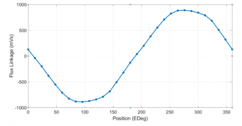
Based on the required parameters of the proposed motor from the analytical calculation given in Table 2, in this part, electromagnetic parameters is simulated and analyzed via the FEA. The model of 2D mesh for both stator and rotor is shown in Figure 4. The distribution of magnetic flux density in both stator and rotor is pointed out in Figure 5. The maximum value reaches 2.378T. The distribution of flux linkage is presented in Figure 6. It can be seen that it is very smooth and sinousoidal.
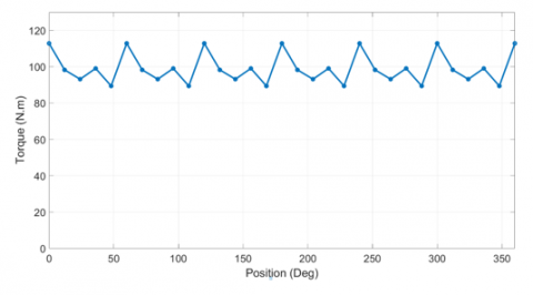
The waveform distribution of back EMF is illustrated in Figure 7. It can be observed that the waveform of back EMF is not sinousoidal with the high harmonic components. Figure 8 depicts the waveform of output torque. The maximum value is 112N.m and 74.5N.m for the average torque. Its torque ripple is indicated in Figure 9, with the value of under 3.5%. The torque ripple plays a crucial role in the design, and one major factor contributing to torque ripple is the cogging torque, as depicted in Figure 10. This result indicates the motor's stability and smooth operation, which are essential considerations in the overall design.
Figure 4. Model of 2D mesh
Figure 5. Distribution of magnetic flux density in both stator and rotor
Figure 6. Distribution of waveform of linkage flux
Figure 7. Distribution of waveform of back EMF
Figure 8. Distribution of waveform of output torque
Figure 9. Distribution of waveform of torque ripple
Figure 10. Cogging torque waveform
Figure 11. Thermal equivalent circuit diagram
Figure 12. Radial (top) and axial (bottom) view results of the thermal model
Figure 11 presents the distribution of thermal equivalent circuit diagram with the heat distribution shown with corresponding temperature values in different colors. It can be seen that at the position of stator winding with yellow nodes and thermistors, the temperature in this area is larger than the remaining positions. The radial and axial results of the thermal model are illustrated in Figure 12. It can be seen that the maximum temperature is 224.4℃ at the middle of the stator winding, and the minimum temperature is 129.2℃ on the external surface of the motor body. For other areas such as the postions of stator and rotor yokes, the temperature rise has a trend of reduction. Through the map of temperature distribution, designers and manufactures can give suitable solutions for cooling and insulation for the motor.
The SPMSM with outer rotor configuration of 7.5kW paper has successfully designed with the two processes: analytical calculation and FEA, where the analytic approach was proposed to defined required parameters of the propsed motor, and the FEA was then introduced to validate and simulate electromagnetic parameters, including magnetic flux density, linkage flux, back EMF, output torque, torque ripple and cogging torque. The achieved results have shown the working characteristics of the motor, especially the cogging torque and torque ripple values. These values will affect the motor's output torque and the vibration and noise of the motor under operation conditions. In addition, via the thermal equivalent circuit model, the temperature distribution at the different regions of the motor has also indicated. Finally, based on the obtained results, designers, researchers and manufacturers can be considered as a reference data to give the suitable prototype design of the SPMSM with outer rotor type.
This work facilitates the groundwork for future studies, potentially involving optimization methods like genetic algorithms and swarm optimization to refine design calculations.
[1] Taha, H.M., Alnaab, I. (2019). Designs of PMSMs with inner and outer rotors for electric bicycle applications. Kurdistan Journal of Applied Research, 4(1): 20-25. https://doi.org/10.24017/science.2019.1.4
[2] Bhat, S.B., Nikam, S.P., Fernandes, B.G. (2014). Design and analysis of ferrite based permanent magnet motor for electric assist bicycle. In 2014 International Conference on Electrical Machines (ICEM), Berlin, Germany, pp. 106-111. https://doi.org/10.1109/ICELMACH.2014.6960166
[3] Zhang, P., Sizov, G.Y., Demerdash, N.A. (2011). Comparison of torque ripple minimization control techniques in surface-mounted permanent magnet synchronous machines. In 2011 IEEE International Electric Machines & Drives Conference (IEMDC), Niagara Falls, ON, Canada, pp. 188-193. https://doi.org/10.1109/IEMDC.2011.5994641
[4] Choi, J.Y., Park, H.I., Jang, S.M., Lee, S.H. (2011). Design and analysis of surface-mounted PM motor of compressor for electric vehicles applications according to slot/pole combinations. The Transactions of the Korean Institute of Electrical Engineers, 60(10): 1846-1857. https://doi.org/10.5370/KIEE.2011.60.10.1846
[5] Manh, T.H., Minh, D.B., Minh, T.P., Quoc, V.D. (2023). Investigation of the influence of skewed slots and degmagnetization effects to line start permanent magnet assistance synchronous reluctance motors. Engineering, Technology & Applied Science Research, 13(1): 9807-9811. https://doi.org/10.48084/etasr.5307
[6] Feng, L., Yu, S., Zhang, F., Jin, S., Sun, Y. (2022). Study on performance of low-speed high-torque permanent magnet synchronous motor with dynamic eccentricity rotor. Energy Reports, 8: 1421-1428. https://doi.org/10.1016/j.egyr.2022.03.018
[7] Lin, J., Schofield, N., Emadi, A. (2013). External-rotor 6-10 switched reluctance motor for an electric bicycle. IECON 2013-39th Annual Conference of the IEEE Industrial Electronics Society, Vienna, Austria, pp. 2839-2844. https://doi.org/10.1109/IECON.2013.6699581
[8] Chan, T.F., Yan, L.T., Fang, S.Y. (2002). In-wheel permanent-magnet brushless DC motor drive for an electric bicycle. IEEE Transactions on Energy Conversion, 17(2): 229-233. https://doi.org/10.1109/TEC.2002.1009473
[9] Huang, V.X. (2012). Modeling of exterior rotor permanent magnet machines with concentrated windings. Doctoral Thesis, Technische Universiteit Delft.
[10] Jung, W.S., Lee, H.K., Lee, Y.K., Kim, S.M., Lee, J.I., Choi, J.Y. (2023). Analysis and comparison of permanent magnet synchronous motors according to rotor type under the same design specifications. Energies, 16(3): 1306. https://doi.org/10.3390/en16031306
[11] Jusoh, L.I., Sulaiman, E., Bahrim, F.S., Kumar, R. (2017). Design comparison of inner and outer rotor of permanent magnet flux switching machine for electric bicycle application. In IOP Conference Series: Materials Science and Engineering. IOP Publishing, 226(1): 012129. https://doi.org/10.1088/1757-899X/226/1/012129
[12] Kim, S.J., Park, E.J., Jung, S.Y., Kim, Y.J. (2017). Transfer torque performance comparison in coaxial magnetic gears with different flux-modulator shapes. IEEE Transactions on Magnetics, 53(6): 1-4. https://doi.org/10.1109/TMAG.2017.2663429
[13] Zhu, Z.Q., Howe, D. (2000). Influence of design parameters on cogging torque in permanent magnet machines. IEEE Transactions on Energy Conversion, 15(4): 407-412. https://doi.org/10.1109/60.900501
[14] Liu, X., Zhang, Z., Xiao, J., Xu, H. (2018). Comparison and analysis of electromagnetic characteristics of IPMSM with single and double layer PMs. International Journal of Applied Electromagnetics and Mechanics, 58(4): 483-496. https://doi.org/10.3233/JAE-180032
[15] Dong, J., Huang, Y., Jin, L., Lin, H. (2016). Comparative study of surface-mounted and interior permanent-magnet motors for high-speed applications. IEEE Transactions on Applied Superconductivity, 26(4): 1-4. https://doi.org/10.1109/TASC.2016.2514342
[16] Pu, T., Du, G., Tong, J., Huang, N., Li, N., Xu, W. (2021). Comparison of rotor strength of various rotor structures for ultra-high-speed permanent magnet synchronous motor. In 2021 IEEE 4th Student Conference on Electric Machines and Systems (SCEMS), Huzhou, China, pp. 1-6. https://doi.org/10.1109/SCEMS52239.2021.9646110
[17] Sahebjam, M., Sharifian, B., Feyzi, M.R., Sabahi, M. (2019). Novel unified control method of induction and permanent magnet synchronous motors. International Journal of Engineering, 32(2): 256-269.
[18] Ponnam, V.K.B., Swarnasri, K. (2020). Multi-objective optimal allocation of electric vehicle charging stations and distributed generators in radial distribution systems using metaheuristic optimization algorithms. Engineering, Technology & Applied Science Research, 10(3): 5837-5844. https://doi.org/10.48084/etasr.3517
[19] Natarajan, S., Kasinathan, G. (2023). A hybrid MIP-CBO approach for loss minimization of the PMSM-fed electric vehicle drive system. Engineering, Technology & Applied Science Research, 13(6): 12278-12283. https://doi.org/10.48084/etasr.6396