Karrar Haider Tajaldin*![]() | Hassan Jassim Motlak
| Hassan Jassim Motlak![]()
© 2024 The authors. This article is published by IIETA and is licensed under the CC BY 4.0 license (http://creativecommons.org/licenses/by/4.0/).
OPEN ACCESS
Solar power plants are desirable because of their low environmental impact and operating costs. However, the efficiency of solar photovoltaic (PV) systems remains challenging due to their nonlinear characteristics. This research proposes novel techniques for tracking the maximal hybrid power point with the goal of improving PV system efficiency. Two well-known shortcomings of traditional maximum power point tracking (MPPT) algorithms are their volatility around the maximum power point (MPP) and their failure accuracy under frequently changing isolation. In order to get over these problems, we put out a theory that uses the Proportional Integration (PI) controller to combine beluga whale optimization (BWO) with perturb and observe (P&O). The effectiveness, intricacy, and simplicity of use of this innovative technique, created by the BWO algorithm and utilizing a Proportional Integration (PI) controller, are compared with traditional P&O and incremental conductance (IC) algorithms in this study. The suggested hybrid PI-BWO approach provides a voltage gain of 2.341 and an average tracking efficiency of about 96.8%, according to MATLAB simulation testing. The P&O theory yielded an efficiency of 93.2% and a voltage gain of 2.25, but the IC technique provided an average efficiency of 95.7% and a voltage gain of 2.28. This method is characterized by its durability, stability, and convenience of use.
maximum power point tracking, perturb and observe, incremental conductance, P&O with proportional integral
The world is currently experiencing a massive demand for electricity as a result of the depletion of fossil fuels [1]. Which negatively affects nature in ways like air pollution, environmental damage, and the non-renewable nature of it [2]. In order to address all of these issues, renewable energy sources offer an alternate source that lowers pollution to the environment because they are cost-effective and can be integrated to supply electricity to remote, urban, and rural areas [3]. One such substitute that is frequently utilized is solar energy, which comes in two flavours: standalone and grid-connected systems [4]. It is necessary to continuously adjust the load voltage to the panel as the PV voltage changes [5]. The installation of a DC/DC converter with an MPPT mechanism will allow for this adaptation. This system makes sure that the photovoltaic panels recover as much energy as possible. MPPT mechanism classification is done using the DC voltage conditioning techniques. Artificial intelligence (fuzzy logic, neural networks, evolutionary algorithms, etc.), hill climbing, perturbation and observation (P&O), and incremental coupling (IC) are the primary algorithms utilized in the literature to control MPPT circuits [6-8].
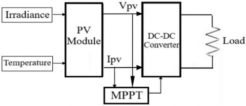
The two primary types of traditional MPPT techniques are P&O and IC [6]. These methods affordability, simplicity, and ease of application have made them widely used. All of these methods, though, have certain drawbacks. When the PV system reaches MPPT, variations in the operating point cause P&O to oscillate around MPP [7]. This is a result of using a fixed perturbation, which eventually causes the energy that is generated to be lost. Furthermore, because of slower convergence, P&O is also unable to track MPP in environments that are changing quickly. Compared to P&O, the IC MPPT technique has a higher algorithmic complexity because it accounts for variations in current in relation to voltage and helps handle abrupt changes in radiation. According to P&O once more, this technique's disadvantage is the uncertainty surrounding step size selection and the oscillations that ensue [8]. Additional straightforward techniques include the fractional open voltage and short circuit methods, which compute MPP using approximation functions for open circuit voltage and current [9]. Control engineering views the PV system as a complex terminal because of its nonlinear characteristics. Different environmental conditions also have an impact on PV systems, so it's important to use a straightforward controller that can adjust to changing conditions [10]. As a result, to track MPP effectively, consistently, and accurately under all operating conditions, a straightforward and reliable controller is needed. Figure 1 the solar system performs better thanks to the converter's controlled duty cycle [11].
When diving into the shortcomings of PV systems, one can explore issues such as inefficient energy conversion, vulnerability to environmental conditions, and challenges in maximizing energy production. For a starting point, you may want to consider the current state of solar energy use and the growing demand for more efficient and reliable photovoltaic systems. The necessity of studying maximum power point tracking (MPPT) algorithms with solar cells arises from the need to optimize the power output of PV systems by dynamically adjusting the operating point to the maximum power point of the solar panel under changing conditions. This becomes critical to enhance overall system performance, increase energy yield, and address limitations associated with fixed operating points in conventional systems. Understanding and improving MPPT algorithms can greatly contribute to the development and efficiency of solar energy use.
Figure 1. Block diagram of PV system [11]
The aforementioned issues are resolved by applying the suggested Perturbation and observation based PI controller. The suggested technology responds quickly to changes in the weather. The PI controller assists in keeping the voltage and current of the Luo converter constant.
Photovoltaic (PV) systems require MPPT techniques for a number of reasons, including efficiency optimization, adaptability to changing conditions, improved system performance, and reduction in system losses. PV panels may lose a sizable portion of their potential energy in the absence of MPPT. By ensuring that the PV system runs at its optimal power point, MPPT reduces these losses.
Efficiency gain and robust performance to guarantee steady and dependable MPPT performance under a variety of circumstances, such as partial shading and temperature fluctuations, are among the goals of MPPT. Furthermore, MPPT is inexpensive and simple to use, requiring neither sophisticated hardware nor a lot of processing power.
Over the past few years, much research has been conducted to develop the efficiency of photovoltaic systems. These studies have explored different approaches and techniques by proposing maximum tracking methods for innovative hybrid power points. In this section, we will discuss some notable works that have contributed to this field.
Calvinho et al. [12] used a new controller for DC-DC converters with the MMPT system based on the PSO algorithm to track the maximum power point of the photovoltaic system to enhance energy production and stability. In the study [13], a perturbation and observation-based algorithm (PGN) and a modified Gauss-Newton were employed to lower computational requirements and increase the accuracy of parameter identification. Amara et al. [14] combined the ANFIS-MPPT algorithm with a PI controller to perform better in various environments when compared to traditional methods. The ANFIS-MPPT command works better than the P&O-MPPT command under a range of irradiance conditions, as seen by the results, which also show acceptable dynamic operations, faster convergence, and less variance of a working point near to MPP.
Mahdi et al. [15] evaluated the effectiveness of soft computing approaches (fuzzy logic and adaptive neuro-fuzzy inference system, or MPPT) with those of standard P&O methods in order to track the maximum power point of PV modules. The MPPT system was modeled and simulated using an MSX-64 PV module and a boost DC-DC converter. These three techniques of MMPT were subjected to a non-shaded pattern, partial shading and shaded of the real weather profile. The capacity to track the MPP under partially shaded conditions and respond to variations in the weather when the system is subjected to a genuine weather profile that is not shaded was demonstrated by these simulated findings. The performance of the traditional P&O-based MPPT has shown how unresponsive this controller is to real weather variations and how unable it is to track the global MPP during partial shading.
This paper examines a stand-alone photovoltaic system consisting of a photovoltaic array, a Luo converter to supply the DC load at the output, and an MPPT controller (P&O, IC and P&O with PI). The model for every component of the system is as follows:
3.1 Photovoltaic array
The photovoltaic system generates electricity from solar radiation. Figure 2 shows the single diode of photo-voltaic module that illustrates the independent photovoltaic system that this article will evaluate [16].
Figure 2. PV cell: (a) External appearance (b) Single-diode equivalent circuit [16]
Through one or more solar panels-photovoltaic panels are mostly constructed of solar cells-a photovoltaic device transforms solar energy into electrical energy. Series or parallel connections are made between the solar cells, depending on the necessary voltage and current. Depicts the PV model's circuit schematic. When solar cells are joined in series, the panel's voltage increases, and when they are connected in parallel, the panel's current value increases [17].
Eq. (1) is used to calculate the solar photovoltaic system's current (I).
$I=I_{P H}-I_D-I_{s h}$ (1)
where,
$I_{P H}$: photovoltaic current
$I_D$: Diod current
$I_{s h}$: Shunt current
The diode characteristic equation ($I_D$) is computed using Eq. (2).
$I_D=I_S\left[\exp \left(\frac{q\left(V_L+I_L R_S\right)}{n K T}\right)-1\right]$ (2)
where,
$I_S$: Series current
$V_L$: Load voltage
$I_L$: Load current
$R_S$: Series resistance
K=Boltzmann constant (1.38×10⁻²³J/K)
T=PV cell temperature (K)
n=Diode ideality factor (1 for ideal diode)
Eq. (3) is used to calculate the leakage shunt current ($I_{s h}$).
$I_{s h}=\frac{V_L+I_L R_S}{R_{s h}}$ (3)
3.2 Positive output super-lift Luo converter (POSLLC)
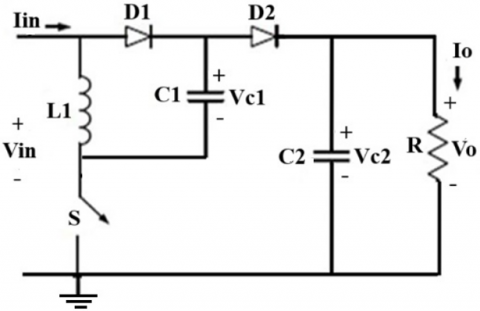
The POSLLC has more performance in terms of extraordinary voltage improvement, high voltage gain, high power density and least output voltage ripple. The POSLLC circuit is used to raise the DC voltage, but some circuits can also be used to lower the voltage, same performance as buck boost converter [18]. The super-lift Luo converter increases the output voltage with a positive polarity, thus increasing the gain in the transmission voltage [19]. The POSLLC converter is divided into sub, main and extra. The main circuit consists of a switch, inductor and two capacitors with two diodes connected to the load. The POSLLC transformer components are calculated using equations for each part [20]. In main series, there are three circuits in the high positive output Lou converter are called as Elementary circuit, Re-lift circuit and Triple-lift circuit [21]. The Luo ultra-thin transformer features a low-side MOSFET switch, geometric progression, and a high voltage step-up ratio. It is well known that all DC-DC converters operate best when the input voltage is reduced using an electrical switch. The switch has two modes of operation: on and off. Diode D2 is reverse biased and diode D1 is forward biased when turned on. The input voltage is the same as the parallel energy storage voltages of the capacitor (C2) and inductor (L). Diode D1 is reverse biased and diode D2 is forward biased when the circuit is turned off. Discharge power route of the capacitor (C2) and inductor (L) when the load is supplied in series. Figure 3 shows the elementary circuit [19].
Analysing the combined system, you'll need to consider the interactions between the PV array and the converter. For example, changes in the output power of the PV array may require adjustments in the converter to maintain optimal operating conditions. Likewise, modifications in the converter parameters might influence how efficiently the PV array's output is utilized. To assess overall work efficiency, it's essential to perform a comprehensive analysis, considering factors such as power losses, voltage regulation, and overall system stability. Simulation tools and mathematical modelling can aid in this process, allowing you to explore different scenarios and fine-tune parameters for maximum efficiency. Remember, the synergy between the PV array and the converter is key to achieving an efficient and reliable solar power system. As you delve into the details of parameter changes, you'll gain valuable insights into optimizing the overall performance of the system.
Figure 3. POSLC circuit [19]
In order to ensure effective operation and compliance with design requirements, the choice of passive component values in the positive super-lift Luo converter should take into account a number of factors. The following are some general guidelines and considerations usually taken during the selection process:
Inductance Value: The inductance value L is crucial for controlling the ripple current and maintaining continuous current mode (CCM). It is generally chosen based on the desired ripple current $\Delta I_L$ and the switching frequency $f_s$.
$L=\frac{\left(V_{\text {in }} \times D\right)}{f_s \times \Delta I_L}$
where, $V_{ {in }}$ is the input voltage, D is the duty cycle, and $\Delta I_L$ is the peak-to-peak inductor current ripple.
Current Rating: The inductor should have a current rating that exceeds the peak inductor current to avoid saturation. The peak current $I_{L_{\text {peak }}}$ can be approximated by:
$I_{L_{\text {peak }}}=I_{L_{\text {avg }}}+\frac{\Delta I_L}{2}$
where, $I_{L_{\text {avg }}}$ is the average inductor current.
Core Material: The core material of the inductor should be chosen to minimize core losses at the operating frequency.
Input Capacitor ($C_{i n}$): The input capacitor helps to reduce the voltage ripple on the input side and should have a low Equivalent Series Resistance (ESR) to handle the high-frequency components of the input current. The capacitance value can be estimated by:
$C_{i n} \geq \frac{I_{L_{\text {avg }}} \times D}{f_s \times \Delta V_{i n}}$
where, $\Delta V_{{in }}$ is the allowable input voltage ripple.
Output Capacitor $C_{{out }}$: The output capacitor filters the output voltage ripple. Its value is selected based on the desired output voltage ripple $\Delta V_{{out }}$:
$C_{\text {out }} \geq \frac{I_{\text {out }} \times D}{f_s \times \Delta V_{\text {out }}}$
where, $I_{\text {out }}$ is the output current.
Switching Capacitor ($C_{s w}$): For converters with additional switching capacitors (as in some advanced topologies like the super-lift Luo converter), the capacitance value should be high enough to maintain the voltage levels during switching transitions.
Voltage Rating: The diodes used should have a reverse voltage rating higher than the maximum output voltage of the converter.
Current Rating: The diodes should be able to handle the peak current without significant losses. The average current through the diode can be approximated by:
$I_D=I_{\text {out }}$
Switching Speed: Fast recovery diodes or Schottky diodes are often preferred for their low forward voltage drop and fast recovery times, which are crucial for high-frequency operation.
Duty Cycle (D): The duty cycle is critical for determining the conversion ratio and is chosen based on the desired output voltage $V_{\text {out }}$ and input voltage $V_{\text {in }}$.
$D=1-\left(\frac{V_{\text {in }}}{V_{\text {out }}}\right)$
Efficiency Considerations: To reduce power losses, high-efficiency components are chosen. This entails selecting MOSFETs with low on-resistance, inductors with efficient core materials, and components with low ESR.
Thermal Management: To ensure dependable operation under all anticipated load conditions, components are selected not only on the basis of electrical specifications but also taking into account their thermal performance.
EMI and Filtering: To guarantee that the converter satisfies regulatory requirements and to lessen electromagnetic interference (EMI), additional filters may be designed.
To attain this optimization, the components’ values for a positive super-lift Luo converter’s passive parts are chosen with care for good performance, efficiency, and reliability. Furthermore, detailed calculations and sometimes iterative trials and prototypes help to fine-tune each component’s value and specification.
3.3 Maximum power point tracking techniques
Maximizing the power produced by PV arrays while regulating the maximum useful voltage is the main objective of MPPT. This implies that MPPT controls the PV array's output. MPPT increases the extracted power output's efficiency by at least 30% in comparison to non-MPPT systems. The literature recommends a number of MPPT techniques, such as the study [22].
3.3.1 Perturb and observe (P&O) method
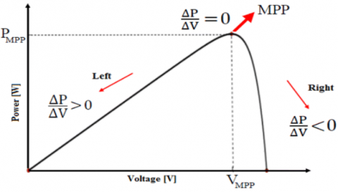
This method tracks the MPP of a PV system on a mirror scale to account for fluctuations in PV module power. The output power can be measured and compared to the output power measured earlier. It is also checked on a regular basis. Sometimes, when power levels rise, the same process is repeated to keep the P&O from reverting. A PV module's power is determined by its voltage and current; when these change, the module's power also changes. The P&O algorithm is forced to use the MPP in order to get the maximum power outcome and to increase and decrease the PV outcome [23]. As seen in Figure 4 [24], the perturb and observe approach is a hill climbing strategy that finds the maximum position in the power curve in the event that the electric array is operating. Figure 5 is a flowchart that illustrates the procedure.
Figure 4. P&O method [24]
Certainly, let's delve into the details of the P&O algorithm and its utilization in maximizing power output from a PV system. In Figure 4, the P&O algorithm is illustrated. Usually, the algorithm modifies the PV system's operational point and tracks the ensuing shift in power output. The goal is to iteratively adjust the operating point until the maximum power point (MPP) is reached. Analyzing the diagram involves understanding how the algorithm responds to changes in the PV output. When the algorithm detects an increase in power, it continues in the same direction, assuming it is approaching the MPP. Conversely, if the power decreases, the algorithm reverses direction, believing it overshot the MPP. The rates of rise and fall essentially determine the step size or the magnitude of perturbation in the operating point. A smaller step size can result in a more precise tracking of the MPP but might take longer to converge, while a larger step size can speed up convergence but risks overshooting the optimal point. It's crucial to strike a balance in choosing appropriate rates of rise and fall. Too aggressive settings might lead to oscillations around the MPP, reducing overall efficiency. On the other hand, overly conservative settings might slow down the algorithm's response to dynamic changes in environmental conditions. The success of the P&O algorithm relies on its adaptability to varying conditions, such as changes in solar irradiance or temperature. Through careful tuning and analysis, you can optimize the algorithm's parameters to ensure a robust and efficient tracking of the MPP under different scenarios. In summary, Figure 4 highlights the dynamics of the P&O algorithm, emphasizing the importance of rates of rise and fall in achieving an effective balance between accuracy and responsiveness in maximizing power output from the PV system [24].
(a)
(b)
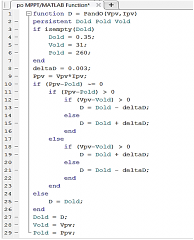
Figure 5. (a) Flowchart of P&O, (b) Pseudo-code of P&O
3.3.2 Incremental conductance (IC) method
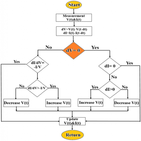
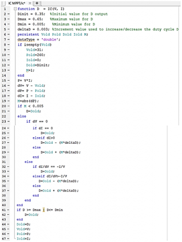
The tracking algorithm of the IC technique uses the slope of the PV module characteristic curve as a guide to monitor MPP. PV module characteristic curve's slope as a guide. The operational point is located at the MPP when the slope is zero; it is positioned to the left of the MPP by a positive slope and to the right of the MPP by a negative slope [25]. Through the use of sensors, the IC algorithm keeps an eye on the PV panel's voltage and current. The sensors' ability to detect the maximum operating point [26]. A flowchart in Figure 6 illustrates the IC execution technique. This strategy makes use of all available data to track the MPP by utilizing the system's P-V curve slope.
(a)
(b)
Figure 6. (a) Flowchart of IC method, (b) Pseudo-code of IC method
3.3.3 Adaptive PI with P&O
Adaptive PI with P&O MPPT is a technique used in photovoltaic (PV) systems to maximize the power output of solar panels. This algorithm works by perturbing the operating point of the PV panel and observing whether it results in an increase or decrease in power output. If there is an increase, then it continues to perturb in that direction until it reaches a point where further perturbation results in a decrease in power output. At this point, it assumes that it has reached the MPP and stays at that point until there is a change in operating conditions.
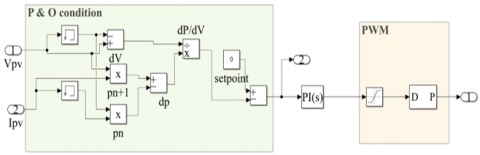
In Figure 7, there is a Matlab simulation of P&O MPPT with a PI controller. This technique can be used in various applications, such as residential solar systems, commercial solar farms, and off-grid systems. This allows it to adapt to changes in operating conditions such as temperature, irradiance, and load [27, 28].
Figure 7. P&O MPPT simulation in Matlab with a PI controller
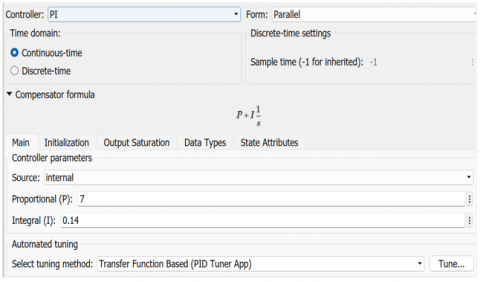
Figure 8. Setting system design for PI controller
In Figure 8, the integral proportional gains are adjusted based on system dynamics by using BWO, ensuring peak performance in many scenarios. The adaptive version of the PI controller is more appropriate for applications with varying operating circumstances or parameters because, unlike the fixed version, it dynamically modifies its parameters in response to changes in the system. The capacity of adaptive PI control to preserve stability and peak performance in the face of unknowns, fluctuating parameters, or disruptions is well established. The P&O algorithm's intrinsic simplicity is enhanced by the adaptive features of the PI controller. By combining the two, the control system can take advantage of the PI controller's flexibility to lessen P&O restrictions such oscillations around the MPP. The BWO method was selected due to its capacity to offer an optimization framework that can adjust the settings of the P&O algorithm and the adaptive PI controller in an effort to strike the best possible balance between efficiency and flexibility. Combining beluga optimization with adaptive PI and P&O may offer a flexible solution appropriate for a range of solar energy system settings, allowing for improved energy extraction while adjusting to changing environmental circumstances.
Based on beluga whale social behavior and hunting strategy, the BWO algorithm is an optimization technique inspired by nature. The BWO algorithm can effectively find optimal or nearly optimal values for the integral gain $\left(K_i\right)$ and proportional gain $\left(K_p\right)$ when used to tune the parameters of a proportional-integral (PI) controller. These values minimize a given performance criterion, such as the Integral of Timeweighted Absolute Error (ITAE), Integral of Squared Error (ISE), or Integral of Absolute Error (IAE). This is a thorough description of how the beluga whale optimization algorithm can be used to adjust the PI controller's parameters: Steps for Tuning PI Controller using BWO.
$J=\int_0^T t|e(t)| d t$
where, e(t) is the error signal and T is the simulation time.
3.3.4 Beluga whale optimization
Adaptive PI with P&O MPPT is an effective technique for maximizing power output from PV systems. It combines two powerful algorithms to provide fast and efficient tracking of MPP under varying operating conditions. This The PI controller values were selected by the BWO algorithm, which is a relatively new optimization algorithm inspired by the social behavior of beluga whales. This algorithm is designed to solve complex optimization problems by mimicking the social behavior of these intelligent marine mammals. Beluga whales are known for their highly social behavior and their ability to communicate with each other using a variety of vocalizations. They also exhibit cooperative hunting behaviors, where they work together to catch prey. These behaviors have inspired researchers to develop an optimization algorithm that mimics the social behavior of beluga whales. Its work by dividing the search space into several subspaces and assigning each subspace to a group of virtual beluga whales. Each whale in the group searches its assigned subspace for the optimal solution while communicating with other whales in its group using a set of predefined vocalizations. The communication between whales allows them to share information about their search progress and coordinate their movements towards the optimal solution. This collaboration helps to avoid getting stuck in local optima and increases the chances of finding the global optimum. This algorithm has been successfully applied to various optimization problems, including feature selection, image segmentation, and power system optimization. It has shown promising results compared to other popular optimization algorithms such as particle swarm optimization and genetic algorithms. The BWO method was selected due to its capacity to offer an optimization framework that can adjust the settings of the P&O algorithm and the adaptive PI controller in an effort to strike the best possible balance between efficiency and flexibility. In this case, the goal function is to minimize the error between the PV system's actual power output and its MPP, thereby optimizing the PI controller's performance.
Combining beluga optimization with adaptive PI and P&O may offer a flexible solution appropriate for a range of solar energy system settings, allowing for improved energy extraction while adjusting to changing environmental circumstances. The source code of BWO is currently available to public: https://ww2.mathworks.cn/matlabcentral/fileexchange/112830-belugawhale-optimization-bwo/ [29, 30].
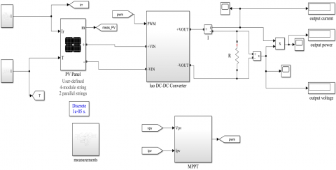
The energy production of solar PV system mainly depends on two variables such as temperature and radiation. The technology for efficient use of solar PV energy is known as MPPT. This technology extracts the highest levels of energy available from solar PV panels by enabling them to operate at maximum efficiency. This paper presents MPPT controllers that are a standard for perturbation and observation (P&O), incremental conduction (IC) and proportional integration (PI). In particular, the performance of the controllers is analyzed. The resilience of a partial-order PI controller based on the Observation and Perturbation Optimization (P&O with PI) algorithm is examined in this research. In a grid connected photovoltaic system. Optimization of parameters of PI controllers is performed. Using the P&O algorithm. This PI controller's performance is contrasted with those of P&O and IC Conventional. An extensive analysis of the linked photovoltaic network's activity. To test the system, MATLAB/Simulink was used. Performance is shown in simulations. The BWO theory was utilized to select the PI controller parameters, and the efficiency of the P&O-PI controller was compared to the MPPT Conventional. Figure 9 displays the basic design of the system with its basic parts: solar cells, a Luo converter, the proposed MPPT controller, and a load resistor, and Figure 10 shows the system's solar cell setup.
Figure 9. MATLAB Simulink design for all system
Figure 10. Setting system design for PV system
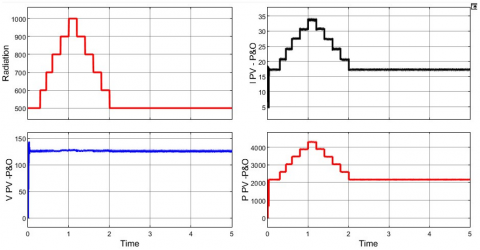
We need to regulate the inverter with a maximum power point tracking point in order to utilize all of the power produced by the PV panel. To extract the maximum power from a PV system at 25ºC and variable of radiation [0.5, 0.6, 0.7, 0.8, 0.9, 1, 0.9, 0.8, 0.7, 0.6, 0.5]×1000 (W/M2), as shown in Figure 11, we will compare updated approaches with classic MPPT methods.
5.1 Result with P&O MPPT
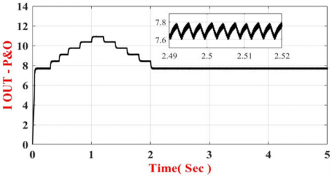
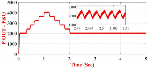
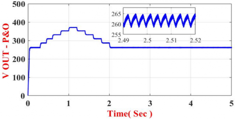
When taking the mean values, we find that the PV system voltage is 125.7 V, the PV system power is 2575 W, and the PV system current is 20.54 A, according to Figure 11. Compared with the improved algorithm, this algorithm exhibits relatively high overshoot and ripple. The average power output in Figure 12 is 2401 W, with an output voltage of 283.1 V, an output current of 8.327 A, an efficiency rate of 93.2%, and a gain voltage of 2.25 between input and output.
Figure 11. P&O MPPT for PV system
(a)
(b)
(c)
Figure 12. Output system for P&O MPPT: (a) Output current, (b) Output power, (c) Output voltage
In Figure 11 the response of the dynamic P&O-MPPT algorithm may exhibit fluctuations during periods of disturbance and monitoring. The MPPT algorithm adjusts the operating point to maximize power output, and these adjustments can cause slight fluctuations before converging to the ideal point.
5.2 Result with IC MPPT
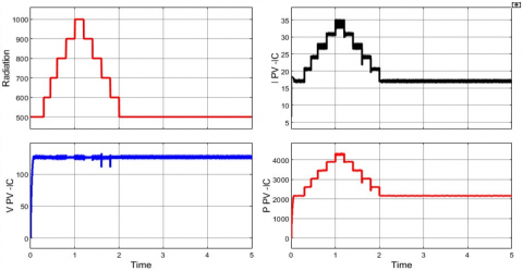
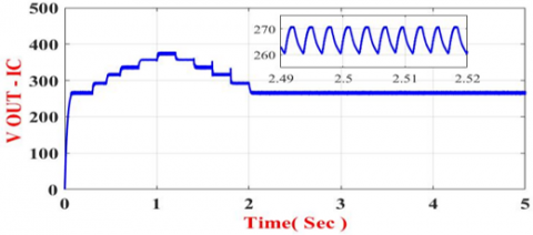
The PV system voltage is 125.8V, the PV system power is 2576W, and the PV system current is 20.46A as shown in Figure 13. As Figure 13 illustrates, the algorithm's performance outperforms P&O in terms of power, ripple, and overshoot, and it more accurately follows the maximum power point. The average power output of 2466W, the output voltage of 287.1V, the output current of 8.443A, the efficiency of 95.7%, and the gain voltage between the input and output are2.28, all shown in Figure 14.
We need specific data from the study or experiment results in order to quantify the performance improvements obtained with the proposed method in comparison to P&O and IC. The effectiveness of MPPT techniques is frequently assessed using metrics such as tracking efficiency, settling time, and other pertinent variables.
Figure 13. IC MPPT for PV system
(a)
(b)
(c)
Figure 14. Output system for IC MPPT (a) Output current, (b) Output power, (c) Output voltage
The general method for calculating these improvements is as follows:
We can calculate the percentage improvements:
For P&O:
Improvement $=\left(\frac{96,8 \%-93.2 \%}{93.2 \%}\right) \times 100 \%=\left(\frac{3.6}{93.2}\right) \times 100 \% \approx 3.86 \%$
For IC:
Improvement $=\left(\frac{96.8 \%-95.7 \%}{95.7 \%}\right) \times 100 \%=\left(\frac{1.1}{95.7}\right) \times 100 \% \approx 1.149 \%$
For P&O:
Improvement $=\left(\frac{5-2}{5}\right) \times 100 \%=\left(\frac{3}{5}\right) \times 100 \%=60 \%$
For IC:
Improvement $=\left(\frac{4-2}{4}\right) \times 100 \%=\left(\frac{2}{4}\right) \times 100 \%=50 \%$
5.3 Result P&O MPPT with adaptive PI
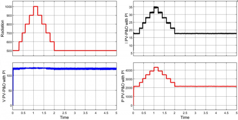
The PV system voltage is 122.7V, the PV system power is 2579W, and the PV system current is 20.95A as shown in Figure 15. When we adapt the P&O to the PI controller by varying its settings using the white whale optimization algorithm, we discover that the efficiency is higher than the two standard theories. This is so that the control system can utilize the flexibility of the PI controller to lessen the effects of the P&O's limitations, like oscillations near MPP, by combining the two.
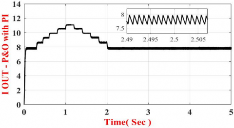
According to Figure 16, with a gain voltage of 2.341 between the input and output, the output voltage is 287.4V, the output current is 8.449A, the average output power is 2496W, and the efficiency is 96.8%.
Table 1 show the value of conventional MPPT and hybrid PI controller MPPT. Through these results, it is clear that the improved method using pi is the best for tracking the maximum power point in solar cells with constant temperature and radiation according to the global system, and even with changing temperatures and radiation as well, it is considered better than the traditional methods of MPPT.
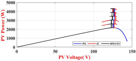
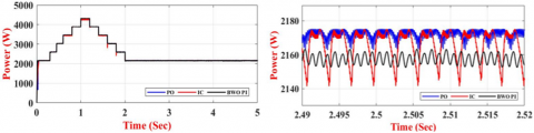
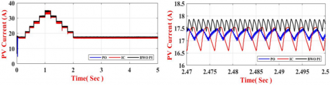
The tracking procedure for the solar cells' maximum power production is displayed in Figure 17. In terms of ripple and oscillation, as well as the value of the generated power in comparison to the power leaving the solar system, Figure 18 compares and contrasts the energy waves generated by MPPT technologies. We note that, in comparison to the other approaches, the hybrid PI method performs the best, reaching an efficiency of 96.8%, which is regarded as a breakthrough. Useful for monitoring peak power points. We note that the fluctuations of the dynamic response in the PI with P&O MPPT algorithm are less than conventional algorithms.
The combination of these techniques and the Luo converter offers a balanced approach, leveraging the strengths of both adaptive PI and P&O MPPT methods to optimize the performance of photovoltaic systems.By using a Luo converter, the system can achieve better power quality with reduced ripple and noise in the output. While Adaptive PI MPPT can quickly adapt to changes in irradiance and temperature, ensuring faster convergence to the maximum power point (MPP).
Table 2 compares the performance of different Maximum Power Point Tracking (MPPT) methods in terms of efficiency (η%) across various studies.
Methods integrating advanced computational techniques (ANFIS, adaptive strategies) tend to achieve higher efficiencies compared to traditional or simpler methods. The proposed adaptive P&O method demonstrates the highest efficiency 96.8%, suggesting that adaptability and real-time optimization are crucial for maximizing the performance of MPPT systems. There is a clear trend toward increasing efficiency over time as methods evolve and incorporate more sophisticated algorithms and adaptive mechanisms. These findings underscore the importance of continuous innovation in MPPT techniques to improve the efficiency and performance of PV systems.
Figure 15. P&O MPPT with PI for PV system
(a)
(b)
(c)
Figure 16. System of output for P&O-PI MPPT (a) Output current, (b) Output power, (c) Output voltage
Figure 17. The dP/dV sign at various points on the power characteristic
(a)
(b)
(c)
Figure 18. Difference output between algorithms MPPT: (a) Power output, (b) PV voltage, (c) PV current
Table 1. Table Results of MPPT methods from MATLAB
|
Parameter |
P&O |
IC |
P&O with PI |
|
Temp ºC |
25 |
25 |
25 |
|
PV Voltage V |
125.7 |
125.8 |
122.7 |
|
PV Current A |
20.54 |
20.46 |
20.95 |
|
PV Power W |
2575 |
2576 |
2579 |
|
Output voltage V |
283.1 |
287.1 |
287.4 |
|
Output current A |
8.327 |
8.443 |
8.449 |
|
Output power W |
2401 |
2466 |
2496 |
|
Efficiency % |
93.2 |
95.7 |
96.8 |
|
Gain |
2.25 |
2.28 |
2.341 |
Table 2. Comparison proposed system with the previous methods
|
Reference |
Year |
Method |
η% |
|
Yu [13] |
2018 |
P&O-PGN |
95% |
|
Amara et al. [14] |
2018 |
ANFIS-MPPT-PI |
96% |
|
Mahdi et al. [15] |
2020 |
P&O-fuzzy logic |
82.125% |
|
The proposed system |
2024 |
Adaptive P&O |
96.8% |
In summary, a major development in the field of solar energy harvesting and control has been made with the adaptation of the Proportional-Integral (PI) algorithm to P&O in solar cells and the optimization of PI parameters using the beluga whale optimization algorithm. The PI and P&O combination works well to create a strong foundation for effective MPPT, which is essential for improving solar photovoltaic systems' overall performance. The potential for utilizing nature-inspired optimization techniques to produce optimal control strategies is demonstrated by the application of the BWO Algorithm for fine-tuning the PI settings. In addition to improving MPPT's speed and accuracy, this hybrid strategy demonstrates resilience in the face of changing and unpredictable environmental conditions. Beluga whale optimization's and PI's effective combination solves some of the long-standing issues with standard MPPT techniques, specifically, the maximum power point's sensitivity to oscillations and changes in parameters. Through PI adaptation to P&O and parameter optimization, the suggested approach yields enhanced tracking efficiency, reaching 96.8%. increased energy productivity, and an effort gain of 2.341, which is relatively better than the traditional IC and P&O algorithms, as the efficiency of the IC algorithm reached 95.7% and a gain of 2.28, while the P&O theory The average efficiency reached 93.2% and an effort gain of 2.25. In conclusion, the BWO algorithm's adaptation of the PI algorithm to P&O with parameter modification offers a viable path forward for improving MPPT methods in solar cells. To confirm its effectiveness in various environmental settings and investigate its suitability for use in actual solar energy systems, more investigation and real-world application are necessary. The restrictions of an MPPT algorithm and an adaptive fractional PI controller will cause a minor increase in system cost and complexity. The P&O MPPT algorithm's low computational requirements and ease of use make it a great choice for real-time implementation. It can be effectively implemented on inexpensive microcontrollers. While, adaptive PI MPPT is more intricate and computationally demanding, which means that real-time implementation is only possible with high-end hardware. Ideal in situations where greater precision is required and processing capacity is available.
Suggestions for Works for the Future
Future research in this field ought to concentrate on tackling particular problems and looking into directions that could lead to significant advancements in solar energy systems. Future work on this project should produce not just improved control strategies for DC-DC Luo converters but also useful knowledge that can be immediately implemented to improve the effectiveness and efficiency of solar energy systems. Investigating these particular paths can help achieve the more general objectives of enhancing renewable energy harvesting technologies, making them more dependable, flexible, and appropriate for a variety of uses.
|
$I_d$ |
Current diode |
|
$I_{s h}$ |
Leakage shunt current |
|
$R_{s h}$ |
Shunt resistance |
|
I |
Solar photovoltaic current |
[1] Djellad, A., Belakehal, S., Chenni, R., Dekhane, A. (2021). Reliability improvement in serial multicellular converters based on STATCOM control. Journal Européen des Systèmes Automatisés, 54(4). https://doi.org/10.18280/jesa.540401
[2] Sharma, S., Sood, Y.R., Sharma, N.K., Bajaj, M., Zawbaa, H.M., Turky, R.A., Kamel, S. (2022). Modeling and sensitivity analysis of grid-connected hybrid green microgrid system. Ain Shams Engineering Journal, 13(4): 101679. https://doi.org/10.1016/j.asej.2021.101679
[3] Wadawa, B., Errami, Y., Obbadi, A., Sahnoun, S. (2021). Robustification of the H∞ controller combined with fuzzy logic and PI&PID-Fd for hybrid control of wind energy conversion system connected to the power grid based on DFIG. Energy Reports, 7: 7539-7571. https://doi.org/10.1016/j.egyr.2021.10.120
[4] Pandey, A., Pandey, P., Tumuluru, J.S. (2022). Solar energy production in India and commonly used technologies-An overview. Energies, 15(2): 500. https://doi.org/10.3390/en15020500
[5] Djidimbélé, R., Kidmo, D.K., Tchaya, G.B., Djongyang, N. (2021). Optimization of the power flow of photovoltaic generators in electrical networks by MPPT algorithm and parallel active filters. Energy Reports, 7: 491-505. https://doi.org/10.1016/j.egyr.2021.07.103
[6] Bhattacharyya, S., Samanta, S., Mishra, S. (2020). Steady output and fast tracking MPPT (SOFT-MPPT) for P&O and InC algorithms. IEEE Transactions on Sustainable Energy, 12(1): 293-302. https://doi.org/10.1109/TSTE.2020.2991768
[7] Kollimalla, S.K., Mishra, M.K. (2014). A novel adaptive P&O MPPT algorithm considering sudden changes in the irradiance. IEEE Transactions on Energy Conversion, 29(3): 602-610. https://doi.org/10.1109/TEC.2014.2320930
[8] Liu, F., Duan, S., Liu, F., Liu, B., Kang, Y. (2008). A variable step size INC MPPT method for PV systems. IEEE Transactions on Industrial Electronics, 55(7): 2622-2628. https://doi.org/10.1109/TIE.2008.920550
[9] Faranda, R., Leva, S. (2008). Energy comparison of MPPT techniques for PV Systems. WSEAS Transactions on Power Systems, 3(6): 446-455.
[10] Wittenmark, B. (1989). Adaptive control. Addison-Wesley.
[11] Sahu, R.K., Shaw, B., Nayak, J.R. (2020). Fractional-order PID controller optimized by SCA for solar system. In Proceedings of International Conference on Artificial Intelligence, Smart Grid and Smart City Applications: AISGSC 2019. Springer International Publishing, pp. 1-10. https://doi.org/10.1007/978-3-030-24051-6_1
[12] Calvinho, G., Pombo, J., Mariano, S., do Rosario Calado, M. (2018). Design and implementation of MPPT system based on PSO algorithm. In 2018 International Conference on Intelligent Systems (IS), Funchal, Portugal. pp. 733-738. https://doi.org/10.1109/IS.2018.8710479
[13] Yu, M.Q. (2018). Parameter identification of photovoltaic cell model based on perturbation and observation and modified Gauss-Newton method. In 2018 37th Chinese Control Conference (CCC), Wuhan, China, pp. 6127-6131. https://doi.org/10.23919/ChiCC.2018.8483101
[14] Amara, K., Fekik, A., Hocine, D., Bakir, M.L., Bourennane, E.B., Malek, T.A., Malek, A. (2018). Improved performance of a PV solar panel with adaptive neuro fuzzy inference system ANFIS based MPPT. In 2018 7th International Conference on Renewable Energy Research and Applications (ICRERA), Paris, France, pp. 1098-1101. https://doi.org/10.1109/ICRERA.2018.8566818
[15] Mahdi, A.S., Mahamad, A.K., Saon, S., Tuwoso, T., Elmunsyah, H., Mudjanarko, S.W. (2020). Maximum power point tracking using perturb and observe, fuzzy logic and ANFIS. SN Applied Sciences, 2: 1-9. https://doi.org/10.1007/s42452-019-1886-1
[16] Shomer, A.O., Elzoghby, H.M., Bahgat, M.E., Sharaf, S.M. (2022). Fractional order PID controller design for maximum power point tracking of dynamic loaded PV system. International Journal of Advanced Engineering and Business Sciences, 3(3): 91-106. https://doi.org/10.21608/ijaebs.2022.164919.1051
[17] Hussein, H.A.K., Motlak, H.J. (2022). Improving the design of super-lift Luo converter using hybrid switching capacitor-inductor cell for PV system. Indonesian Journal of Electrical Engineering and Computer Science, 25(2): 710-720. https://doi.org/10.11591/ijeecs.v25.i2
[18] Khalil, H.K., Hreshee, S.S., Motlak, H.J. (2020). Design and implementation of photovoltaic system based on super-lift LUO converter. In Journal of Physics: Conference Series. IOP Publishing, 1530 (1): 012013. https://doi.org/10.1088/1742-6596/1530/1/012013
[19] Dhas, G.J.S., Dhas, D.A.S., Sreesna, M.K. (2016). Positive output elementary superlift luo converter for PV applications. In 3rd International Conference on Innovative Engineering Technologies.
[20] Tekade, A.S., Juneja, R., Kurwale, M., Debre, P. (2016). Design of positive output super-lift Luo boost converter for solar inverter. In 2016 International Conference on Energy Efficient Technologies for Sustainability (ICEETS), Nagercoil, India, pp. 153-156. https://doi.org/10.1109/ICEETS.2016.7582916
[21] Luo, F.L., Ye, H. (2003). Positive output super-lift converters. IEEE Transactions on Power Electronics, 18(1): 105-113. https://doi.org/10.1109/TPEL.2002.807198
[22] Ali, M.H.M., Mohamed, M.M.S., Ahmed, N.M., Zahran, M.B.A. (2022). Comparison between P&O and SSO techniques based MPPT algorithm for photovoltaic systems. International Journal of Electrical & Computer Engineering, 12(1): 32-40. https://doi.org/10.11591/ijece.v12i1.pp32-40
[23] Chitransh, A., Kumar, S. (2021). The different type of MPPT techniques for photovoltaic system. Indian Journal of Environment Engineering, 1(2): 1-4. http://doi.org/10.54105/ijee.A1809.111221
[24] Maheswari, N.V.U., Shanthi, L.J.S. (2022). Implementation of modified incremental conductance MPPT algorithm in grid connected PV system under dynamic climatic conditions. Indian Journal of Science and Technology, 15(17): 819-828. https://doi.org/10.17485/IJST/v15i17.282
[25] Owusu-Nyarko, I., Elgenedy, M.A., Abdelsalam, I., Ahmed, K.H. (2021). Modified variable step-size incremental conductance MPPT technique for photovoltaic systems. Electronics, 10(19): 2331. https://doi.org/10.3390/electronics10192331
[26] Dhinesh, V., Vijayakumar, D.G., Saravanan, D.S. (2020). A photovoltaic modeling module with different converters for grid operations. International Journal of Innovative Research in Technology, 6(8): 89-95.
[27] Sahoo, J., Samanta, S., Bhattacharyya, S. (2020). Adaptive PID controller with P&O MPPT algorithm for photovoltaic system. IETE Journal of Research, 66(4): 442-453. https://doi.org/10.1080/03772063.2018.1497552
[28] Kler, D., Rana, K.P.S., Kumar, V. (2018). A nonlinear PID controller based novel maximum power point tracker for PV systems. Journal of the Franklin Institute, 355(16): 7827-7864. https://doi.org/10.1016/j.jfranklin.2018.06.003
[29] Zhong, C., Li, G., Meng, Z. (2022). Beluga whale optimization: A novel nature-inspired metaheuristic algorithm. Knowledge-Based Systems, 251: 109215. https://doi.org/10.1016/j.knosys.2022.109215
[30] Baihaqi, M.A., Utama, D.M. (2023). No-Wait flowshop permutation scheduling problem: Fire hawk optimizer vs beluga whale optimization algorithm. Jurnal Ilmiah Teknik Industri, 22(1): 124-136. https://doi.org/10.23917/jiti.v22i1.21128