Youssouf Bouthiba*![]() | Billel Meghni
| Billel Meghni![]() | Abdellatif Cherifi
| Abdellatif Cherifi![]() | Ali Belhamra
| Ali Belhamra![]()
© 2024 The authors. This article is published by IIETA and is licensed under the CC BY 4.0 license (http://creativecommons.org/licenses/by/4.0/).
OPEN ACCESS
In this work, a grid-connected hybrid energy system composed of wind/PV/FC/DG with a HESS based on a battery and supercapacitor. To protect the latter from deep discharge and enhance network flexibility, we use a diesel generator. The objectives of this research are: For generator-side control systems, we apply the TSR strategy for the wind power generator and the FLC strategy for the photovoltaic generator to achieve maximum energy operation. On the management side, we proposed and implemented a new hybrid intelligent energy management strategy based on the FLC-ANN to balance energy supply and demand and increase the life cycle of the proposed system. As for the grid side, the DPC-FLC was applied to control the flow of active and reactive power flowing in the grid. To evaluate the effectiveness of the proposed controllers under changing conditions in energy demand and climate, a simulation test of the proposed system was conducted using the Matlab-Simulink platform. Finally, the results obtained demonstrated the efficiency of the proposed system in terms of the feasibility and effectiveness of the proposed control techniques, in addition to the THD of the network current, which reached 0.34%, which contributes to improving the power quality of hybrid systems.
HES, Grid, HESS, FLC-ANN, DPC-FLC, TSR
Currently, renewable energies are characterized by their intermittent and unpredictable nature, which causes problems in the quality factor and the balance factor between energy production and consumption [1]. We also find that individual energy sources cannot solve these problems, so two or more energy sources (renewable or non-renewable) can be combined to form a hybrid system [2]. In addition, to increase the efficiency of the systems of these energies and establish a balance between consumption and energy production, energy storage is controlled by charge and discharge [3], as there are different types of energy storage systems integrated into RESs, for example: PV/Wind/Battery [4], Wind/Flywheel [5], Wind/SC [6]. Nevertheless, these types do not meet consumption and energy density at the same time, so it is proposed to combine two or more heterogeneous and complementary storage systems (ESS) to form a hybrid system (HESS), such as Battery/SMES [7], Battery/H2 [8], Battery/SC [9]. In this regard, the HESS component of a battery pack and flywheel has been applied to a PV system to supply a residential load [10], and further applied to a wind system [11]. and to power a micro-grid, HESS applied a battery/supercapacitor component to a standalone PV system [12]. Garcia et al. [13] applied HESS (battery/hydrogen) to a wind/PV system. And when designing a control unit for HESS, we face some challenges; for example, we must take into account the controls of each storage element and how the power is distributed between them [7] and the unbalanced load that leads to poor power quality. In order to get rid of the limitations of these challenges, the researchers proposed control strategies to achieve balance between demand and power generation by relying on the PI controller to share power between HESS elements (battery and supercapacitor) [14], as well as controlling the battery and the supercapacitor based on a low-pass filter-PI [9]. The researchers proposed a coordination control to regulate the energy on the one hand and absorb the unbalanced energy in MG on the other hand [15]. I also propose a predictive technique that maintains the SOC and the voltage of the HESS (battery and supercapacitor respectively) elements within the allowable ranges [16], and to improve the management of hybrid systems in terms of efficiency and durability, an FLC-based EMS system was provided to optimally control the output power of FC system [17]. As it was done, a multi-mode logical power distributor strategy was also proposed to solve the problem of a mismatch between demand and generation for a hybrid power system based on an integrated photovoltaic system with HESS [18]. In addition, another energy management strategy based on an artificial neural network (ANN) was proposed for the reverse osmosis desalination unit for the smooth transition of the generated energy [19]. Moreover, an artificial neural network based on Hybrid Bat Search algorithm (HBSANN) and Combined Cuckoo algorithm (CCSNN) was used for energy management in order to enhance the power sharing between HESS elements [1, 20]. Recently, to improve the power management of HESS, the FOPI-PSO controller was implemented [21], and to make wireless charging highly efficient for electric vehicles, the circle search algorithm (CSA) and quantum neural networks (QNN) were combined [22].
In this study, the supercapacitor was integrated with the battery to assist it during charging and discharging processes by alternating, forming a highly efficient hybrid energy storage system (HESS), knowing that it is difficult to control the energy balance effectively between the sources, the capacitor, the battery, and the load in hybrid energy systems by applying conventional control strategies, which represents a challenge due to the variable and non-linear nature of these systems.
To address this challenge, we propose a new intelligent hybrid energy management strategy based on the combination of the Fuzzy Logic Control (FLC) unit and Artificial Neural Network (ANN) unit, which has the ability to deal with complex and nonlinear systems, which is the main contribution of this paper. The goal of this strategy is to improve the management of energy flow between the elements of the hybrid energy system, ensuring efficiency and optimal performance.
The control systems proposed in this study are implemented on the proposed hybrid energy system (PV/wind/FC/DG/battery/SC) to enhance energy production according to three main aspects, as follows:
1) The first aspect is that the generators are controlled to achieve maximum power point tracking (MPPT) by applying TSR technology for wind power generators and fuzzy logic technology for photovoltaic generators. 2) The second aspect is the energy management of the proposed system. To achieve optimal management, an intelligent hybrid strategy was implemented consisting of an FLC unit and an ANN unit working as a unified system with the addition of two PI controllers to achieve the reference tracking required for HESS where the fuel cell is controlled by the PI controller in order to track the reference value of the DC bus. 3) The third aspect, the active and reactive power flowing into the grid, is controlled by implementing Direct Power Control based on the Fuzzy Logic Controller (DPC-FLC).
This paper is organized as follows: Section 2 describe the modeling and control of its different parts of the studied hybrid energy system. In Section 3, the HES management strategy proposed is described. In Section 4, grid-side converter DC/AC is control. In Section 5, are presented the results simulations- MATLAB/Simulink and discussed. Finally in Section 6 a conclusion for this work.
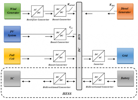
Figure 1 shows the studied hybrid energy system, where the latter is composed of a conventional energy source (diesel generator), three renewable energy sources wind /PV/FC/DG and a hybrid energy storage system (battery / supercapacitor). All of the above elements are connected with control/non-control converter in parallel with the network to provide the necessary power.
Figure 1. Proposed hybrid energy system
2.1 PV system model
The solar cell and the mathematical expression for the current produced through it can be represented according to Eq. (1) [23].
$I=I_{p v}-I_0\left[\exp \left(\frac{V+R_s I}{V_t \alpha}\right)-1\right]-\frac{V+R_s I}{R_p}$ (1)
where: $I$ and $V$ represent the PV cell output current and voltage respectively; $I_0$ is the diode saturation current and $I_{p v}$ is actual light-generated current; $R_p$ and $R_s$ are the PV cell's parallel and series resistances respectively; $V_t$ is the thermal junction voltage; α is the diode constant.
2.1.1 Control MPPT based FLC
In this work, an MPPT technique based on fuzzy logic control (FLC) of a photovoltaic system has been implemented. Despite the challenges it faces of the MPPT-fuzzy logic control technique, it has the ability to easily select the maximum power point for PV panels [24]. The fuzzy rules of this technique are designed according to Table 1, which basically contains the inputs, usually E and ΔE, which are determined according to the Eqs. (2) and (3) (such that dP/dV disappears at MPP) in order to determine the ΔD that is the output, for example, if E is PB it means that the operating point is far to the left from the MPP consequently, ΔD will be PB for increasing duty ratio if ΔE is ZE [25].
Table 1. FLC rules applicable to the MPPT-PV
|
CE |
E |
||||
|
NB |
NS |
ZE |
PS |
PB |
|
|
NB |
NB |
NB |
NB |
NB |
ZE |
|
NS |
NB |
NS |
NS |
ZE |
PS |
|
ZE |
NB |
NS |
ZE |
PS |
PB |
|
PS |
NS |
ZE |
PS |
PB |
PB |
|
PB |
ZE |
PS |
PB |
PB |
PB |
$E(k)=\frac{P(k)-P(k-1)}{V(k)-V(k-1)}$ (2)
$\Delta E(k)=E(k)-E(k-1)$ (3)
where, E: Error, ΔE: Change in error, ΔD: Change in duty ratio, NB: Negative Big, NS: Negative Small, ZE: Zero, PS: Positive Small, and PB: Positive Big.
2.2 Wind turbine model
The following equation expresses the amount of aerodynamic force applied to the plane of the turbine rotor [26]:
$P_{{are }}=C_p \cdot P_v=C_p(\lambda, \beta) \cdot \frac{\rho \cdot S \cdot v^3}{2}$ (4)
where, $v$ is the wind speed $(\mathrm{m} / \mathrm{s})$; $S$ is the circular surface swept by the turbine ($m^2$); $\rho$ is the density of air ( $\mathrm{kg} / \mathrm{m}^3$ ); $\lambda$ is the speed ratio; $\beta$ is the pitch angle of the blade. $C_p$ is the power coefficient and $\lambda$ is the speed ratio.
2.2.1 PMSG model
The PMSG model is represented as follows on the d-q axis [27]:
$\left\{\begin{array}{l}V_{s d}=-R_s I_{s d}-L_s \frac{d I_{s d}}{d t}+\omega L_s I_{s q} \\ V_{s q}=-R_s I_{s q}-L_s \frac{d I_{s q}}{d t}-\omega L_s I_{s d}+\omega \varphi\end{array}\right.$ (5)
where, $V_{s d}, V_{s q}, I_{s d}, I_{s q}$: stator voltage and current on the d–q axis respectively; $R_s, L_s$: generator inductance and resistance respectively; $\varphi$: magnet flux; $\omega$: generator speed.
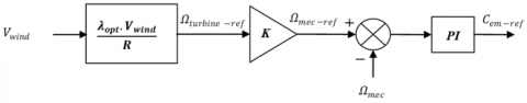
2.2.2 MPPT control
In order to extract the optimal power from wind power, a DC-DC boost converter is used because it is an important part of this study, and a PI controller is used to correct the difference between the required speed (extracted by MPPT) and the actual speed to control the current of the latter [28]. This is done according to Eq. (6) and Figure 2 [29], thus obtaining the optimal power according to Eq. (7) [30].
$\lambda_{o p t}=\frac{R \Omega_{r e f}}{v} \Rightarrow \Omega_{r e f}=\frac{\lambda_{o p t} \cdot v}{R}$ (6)
$P_{o p t}=C_p^{o p t}\left(\lambda_{o p t}, \beta\right) \cdot \frac{\rho \cdot S \cdot v^3}{2}$ (7)
Figure 2. A schematic diagram of the MPPT controller for a wind energy generator
2.3 Fuel cell model
FC can be expressed by the following Eq. (8) and Eq. (9) [31]:
$E=E_{o c}-N A \ln \left(\frac{i_{f c}}{i_0}\right) \cdot \frac{1}{s \frac{T_d}{3}+1}$ (8)
$V_{f c}=E-R_{o h m} \cdot i_{f c}$ (9)
where, $V_{f c}$ is the voltage of the fuel cell (V); $E_{o c}$ is open circuit voltage (V);$i_0$ is exchange current (A); $i_{f c}$ is the current of the fuel cell (A); $R_{\text {ohm }}$ internal resistance (Ω); A is tafel slope (V); the number of cells is N; $T_d$ is the response time.
2.4 Diesel generator model
The electrical power output of a diesel generator is expressed according to the following equation [32]:
$P_m-P_e-D\left(\omega_m-\omega_e\right)=2 H \frac{d \omega_m}{d t}$ (10)
where, $P_e$: electrical power output; $P_m$: mechanical power input; $H$: diesel generator's inertia constant; $D$: factor of damping; $\omega_e$: speed of electrical; $\omega_m$: speed of rotor.
2.5 Hybrid energy storage system (HESS) model
To improve the proposed system's efficiency and address energy quality issues caused by changes in energy demand and climate, a hybrid energy storage system consisting of a battery (lead acid) and a supercapacitor was integrated, in which the battery is given priority during charging and discharging operations. The latter is integrated with DC-Link by means of bidirectional DC-DC buck-boost converters.
2.5.1 Battery model
The battery voltage is expressed according to the following relationships [33]:
$U_{\text {bat }}=E_{b a t}-R_i \cdot i$ (11)
where, Ebat is the no-load voltage; Ri: is the internal resistance of the battery; i is the current of the battery; Ubat is the voltage of the battery.
2.5.2 Supercapacitor model
The output voltage for SC can be expressed according to Eq. (12) [34]:
$V_{s c}=\frac{N_p Q_c}{C_T}-R_{s c} i_{s c}$ (12)
where, $i_{S C}$ and $R_{S C}$ represent the SC's module current (A) and resistance (U), respectively; The electric charge of the cell is denoted by $Q_c$(C).
In this work, we use SOC limits (minimum (SOCmin) and maximum (SOCmax)) to evaluate the range of battery power and SC power allowable according to the following two relationships [35, 36]:
$S O C_{B a t-\min } \leq S O C_{B a t} \leq S O C_{B a t-\text { max }}$ (13)
$S O C_{s c-\min } \leq S O C_{s c} \leq S O C_{s c-\max }$ (14)
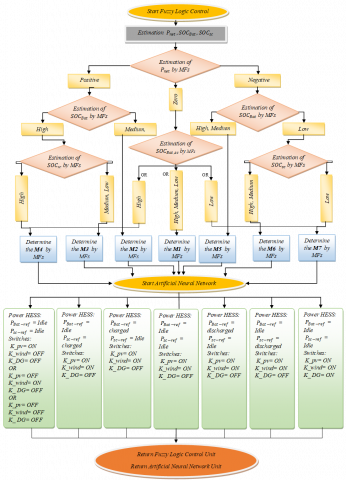
The system in the absence of proper energy management may become unstable, so a new intelligent hybrid energy management strategy was designed and used in order to manage the energy of the proposed system and control the energy flow according to Figure 3 to meet the energy demand of the grid in spite of the changes (changing energy demand and climate change) that occur in our system. This new strategy is based on two basic units, the first is the FLC and the second is the ANN so that both units work together as one system in order to achieve the following objectives:
• Ensuring continuous power supply to the load and keeping constant DC voltage despite changes in the system.
• System component control (HESS, PV, Wind, GD)
• Improving the SOC% of the HESS.
Figure 3. Energy management system flowchart proposed
3.1 A power management strategy proposed (FLC-ANN)
We design the proposed new hybrid energy management strategy according to Figure 4 that relies on artificial intelligence by merging two units of the family of artificial intelligence units to obtain a hybrid unit that operates as one system, where the first unit is FLC and the second unit is ANN.
This hybrid unit determines the HESS reference power and status (ON/OFF) of the K_wind, K_pv and K_DG switches to turn on or off the wind system, PV system, and diesel generator respectively, depending on the SOC of the HESS and net power. Two PI controllers have been added to the proposed management unit to achieve tracking of the required energy references for the HESS. In addition, we use a third PI controller to control the fuel cell in order to maintain DC bus stability in the hybrid system.
Figure 4. The diagram of a power management strategy based on an FLC-ANN
3.1.1 FLC unit control
The fuzzy logic control (FLC)-based controller is the first essential power management part of the proposed hybrid unit, as mentioned and shown in Figure 3 and Figure 4, respectively. It has an intuitive pattern, experience-based of representing action through rules [37]. A unit FLC is determines operating modes (M1, M2, M3, M4, M5, M6 and M7), depending on the SOC of the HESS and the net power by the sample rules proposed in Figure 5 and Table 2.
Figure 5. The first management unit (FLC)
Table 2. Rules applicable to the FLC unit
|
R.N |
INPUT |
OUTPUT |
|
P_net SOC_bat SOC_sc |
M1 M2 M3 M4 M5 M6 M7 |
|
|
R.1 |
P M M |
Off On Off Off Off Off Off |
|
R.2 |
P H M |
Off Off On Off Off Off Off |
|
R.3 |
P H H |
Off Off Off On Off Off Off |
|
R.4 |
Z M M |
On Off Off Off Off Off Off |
|
R.5 |
Z H H |
Off Off Off On Off Off Off |
|
R.6 |
Z L L |
Off Off Off Off Off Off On |
|
R.7 |
N L M |
Off Off Off Off Off On Off |
|
R.8 |
N M H |
Off Off Off Off On Off Off |
|
R.9 |
N H H |
Off Off Off Off On Off Off |
|
R.10 |
N L H |
Off Off Off Off Off On Off |
|
R.11 |
N L L |
Off Off Off Off Off Off On |
P = Positive; Z = Zero; N = Negative H = High; M = Medium; L = Low
3.1.2 ANN unit control
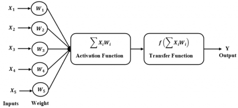
The controller based on an artificial neural network (ANN) is the second essential power management part of the proposed system in this work, as shown in the Figure 3 and Figure 4. The latter (ANN) has been shown to be efficient, robust, and rapid [1]. An artificial neural network (ANN) is a design that simulates the operation of a biological neuron so that it can be created according to Figure 6, which can be summarized as follows [38]:
Figure 6. Artificial neural network model
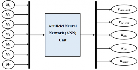
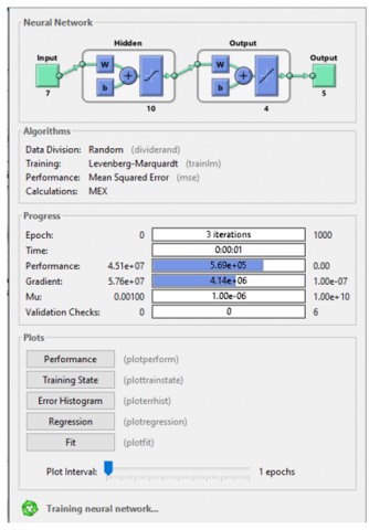
In our study, according to the Figure 7, architecture the neural network consists of 7 inputs ($M_{1,2,3,4,5,6,7}$) and five outputs ($P_{r e f-B a t}, P_{r e f-s c} K_{p v}, K_{\text {wind }}$ and $K_{D G}$), this neural network is trained (e.g. Figure 8) to determine the reference battery power, the SC power, and the K_pv state, And K_wind, and K_DG.
Figure 7. Structure of the proposed neural network
Figure 8. The neural network training stage
3.1.3 ANN training results
Results for training, validation, and target testing are displayed in Figure 9 for the network outputs. Thus, the NN controller was trained using 70% of the training data, 15% of the validation data, and 15% of the target testing. In this respect, based on the regression curves displayed, we conclude that the NN unit has been trained effectively, so all datasets have ideal R- values (R = 1 in all case), as well as the mean square error (MSE) during training is shown in Figure 10 which shows the best performance in validation, with its value of 6.7508e-25 at epoch7.
Figure 9. The ANN controller's regression performance
Figure 10. Validation performance of the ANN
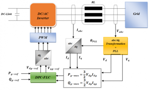
To provide and regulate the required power to the consumers, the active and reactive power between the grid and the hybrid energy system is controlled through the converter control (DC/AC). In this part, to control the active and reactive power flowing in the grid, we propose Direct Power Control (DPC) based on FLC, as shown in Figure 11.
Figure 11. Schematic diagram of grid control
4.1. Model of the grid
We define a frame of reference that rotates synchronously with the grid voltage selected to express the dynamic model of grid connection according to Eq. (15) and Eq. (16) [27]:
$V_{d g}=V_{d i}-R_g I_{d g}-L_{d g} \frac{d I_{d g}}{d t}+L_{q g} \omega_g I_{q g}$ (15)
$V_{q g}=V_{q i}-R_g I_{q g}-L_{q g} \frac{d I_{q g}}{d t}-L_{d g} \omega_g I_{d g}$ (16)
where: $V_{d g}, V_{q g}$: are voltage elements of the grid on the axis of d-q; $V_{d i}, V_{q i}$: are voltage elements of the inverter on the axis of d-q; $R_g$: the resistance of the grid; $L_{d g}, L_{q g}$: are inductance elements of the grid on the axis of d-q; $I_{d g}, I_{q g}$: are current elements of the grid on the axis of d-q.
4.2 Design of a FLC controller
In this study, we use the fuzzy controller to control the active and reactive power. This unit is designed by proposing 9 rules as shown in Table 3. These rules (output variables) are determined depending on the input variables $e_{P_g, Q_g}$ (error of active and reactive power) and $\Delta e_{P_g, Q_g}$ (change in error of active and reactive power), which are specified through Eqs. (17)-(20) respectively. For example, if $e_{P_g, Q_g}$ is NB and $\Delta e_{P_g, Q_g}$ is PB, then the result is ZE. The linguistic variables used in this unit are as follows: ZE is equal zero, PB is positive big, and NB is negative big.
$e_{P_g}=P_{g-\text { ref }}-P_{g-\text { mes }}$ (17)
$\Delta e_{P_g}=\Delta e_{P_s}(k)-\Delta e_{P_g}(k-1)$ (18)
$e_{Q_g}=Q_{g-\text { ref }}-Q_{g-\text { mes }}$ (19)
$\Delta e_{Q_g}=\Delta e_{Q_g}(k)-\Delta e_{Q_g}(k-1)$ (20)
Table 3. FLC rules applicable to the DPC
|
$\boldsymbol{e}_{P_g, Q_g}$ |
$\Delta \boldsymbol{e}_{\boldsymbol{P}_g, \boldsymbol{Q}_g}$ |
||
|
NB |
ZE |
PB |
|
|
NB |
NB |
NB |
ZE |
|
ZE |
NB |
ZE |
NB |
|
PB |
ZE |
PB |
PB |
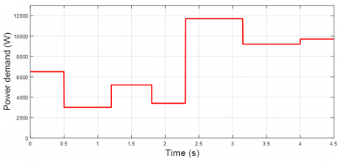
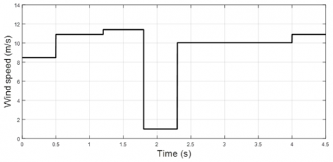
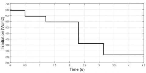
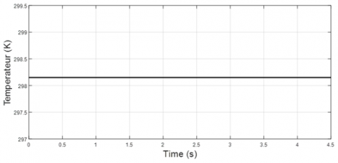
We study the dynamic performance of the studied system by conducting a simulation test on the MATLAB Simulink platform under changing conditions in terms of energy demand and climate: energy demand change, wind speed change, solar radiation change with constant temperature, and HESS state of charge (battery and SC) shown in Figures 12-15, respectively. This is to verify the effectiveness and performance of the proposed controllers that optimize, balance, and share energy between the studied hybrid system elements (PV, wind, etc.) and grid requirements.
We obtained the results by following the following steps:
Figure 12. Profile of the power demand
Figure 13. Profile of the wind speed
Figure 14. Profile of the solar irradiation
Figure 15. Profile of the ambient temperature
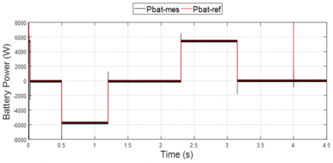
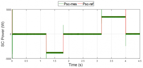
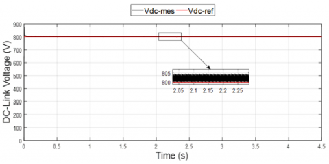
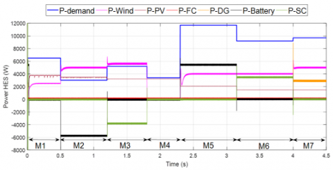
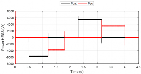
Figure 16 and Figure 17 indicated the tracking power of the references needed for the battery and the supercapacitor, respectively, while Figure 18 illustrates the results of tracking the reference value of the DC bus by controlling the fuel cell, which was shared with other sources and were approximately 200 watts in all modes. The findings shown in Figure 18 and Figure 19 demonstrate attaining energy balance and optimal management of HES, respectively. As a consequence, we discover the source powers for the examined hybrid system are most compatible, as shown by the various patterns observed. Therefore, we interpret each pattern as follows:
Mode 1: Power sources and demand power equal to 6500 W (Pnet = 0), so that 2500 W is generated from the wind generator, 3800 W from the PV source, and 200 W from the FC source. This causes the HESS elements to become inactive (0W) and the diesel generator to stop.
Mode 2: The wind generator outputs 5000 W, the PV generator outputs 3500 W, and the FC source outputs 200 W while the diesel generator is inactive and the demand power is 3000 W less than the source power (Pnet > 0). This indicates that the battery is in charge mode (5700W charge), and the supercapacitor is in rest mode (0W charge/discharge).
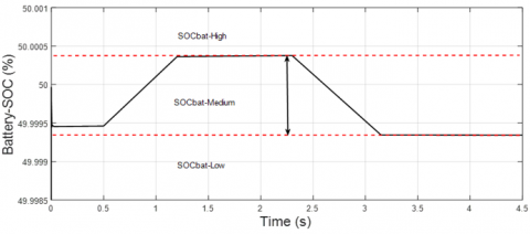
Mode 3: In this mode, the rated request power is 5200 W lower than the sources power (Pnet > 0). So that the photovoltaic generator produces 3200 watts, the wind generator produces 5600 watts, the FC source outputs 200 watts, and the diesel generator output is 0 watts (at idle). On the other hand, the SOCbat has reached its maximum charge, shown in Figure 20, so the battery is in sleep mode (0 W charging), and the supercapacitor is in charging mode to charge the excess power (3800 W charging) in order to support in case of complete discharge of the battery.
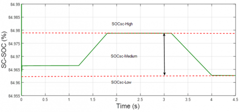
Mode 4: The state of HESS charge reaches its maximum (SOCb > SOCmax and SOCsc > SOCmax) as shown in Figure 20 and Figure 21, so the wind generator is disconnected and the SC stops charging to protect it from overcharging, while the battery and diesel generator will be in their previous states and the photovoltaic generator and the FC supply will remain in operation in order to provide the required power of 3400 W.
Mode 5: In this mode, the power of the sources (6200W) is less than the power required (11700W) (Pnet < 0); in this case, the HESS is discharged, the battery has priority during the discharging process (5500W discharge) in order to support the sources and meet the power needed for the grid , while the SC remains in sleep mode (0 watt discharge) to support the battery when fully discharged, and the diesel generator remains inactive even when needed.
Mode 6: HESS remains discharging to support the sources power (5700 W) and provide the necessary power (9200 W) so that 3500 W of the supercapacitor is discharged while the battery is at rest (0 W discharge) because the SOCbat has reached its minimum (SOCbat < SOCmin), as shown in Figure 20. As for the diesel generator, it remains inactive until the HESS is completely discharged to the minimum discharge (SOCbat < SOCmin and SOCsc < SOCmin).
Mode 7: In this mode, the diesel generator is switched on to replace it with HESS, and this is for two reasons: the first is that the latter has reached its minimum discharge (SOCmin > SOCbat and SOCmin > SOCsc) as shown in Figure 20 and Figure 21, and the second is related to the sources' inability to provide the energy needed for the grid.
The results shown in Figure 22 were achieved by managing the energy between the elements of the hybrid energy storage system as follows:
In the case of (P_net = 0), it indicates that the generation power is equal to the demand power and therefore the supercapacitor and battery are inactive.
In the case of (P_net > 0), it indicates the presence of excess energy, and therefore the battery and the supercapacitor alternately charge this energy, and the battery takes priority in charging until it reaches (SOCmax < SOCbat; Figure 20), and after that the supercapacitor intervenes until it reaches (SOCmax < SOCsc; Figure 21).
In the case of (P_net < 0), this indicates a lack of energy, and therefore the battery and the supercapacitor alternately discharge the necessary energy, and the battery takes priority in discharging until it reaches (SOCbat < SOCmin; Figure 20), after which the supercapacitor intervenes until it reaches (SOCsc < SOCmin; Figure 21).
Figure 16. Power of the battery
Figure 17. Power of the SC
Figure 18. Voltage of the DC Link
Figure 19. Powers of the hybrid energy system
Figure 20. State of charge of the battery
Figure 21. State of charge of the SC
Figure 22. Power of the HESS
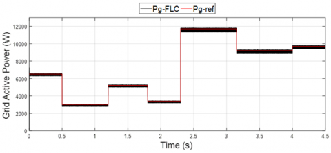
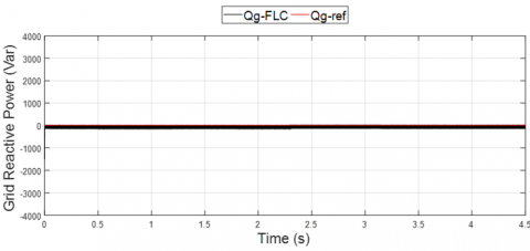
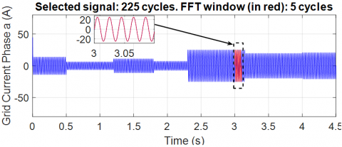
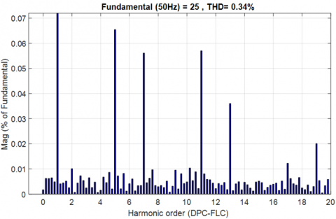
Finally, thanks to the optimal management of the power required for the grid by hybrid energy system, a high quality of power has been achieved by applying a control approach based on Direct Power Control-Fuzzy Logic Control (DPC-FLC) applied to the flow of active and reactive energy in the grid, as shown in Figure 23 and Figure 24. The results of Figure 25 and Figure 26 show the quality of the electrical power output that is injected into the grid, as we note that the THD of the grid current (phase A) was reduced to the lowest distortion (it was 0.34%) by applying the proposed control, and from it we conclude that the technique The proposed control is more robust and effective in terms of reducing distortion and THD.
Figure 23. Active power of the grid
Figure 24. Reactive power of the grid
Figure 25. Grid current phase a for FLC
Figure 26. THD for DPC-FLC
In this paper, a hybrid energy system based on PV / Wind / FC / DG and HESS was presented, with the latter connected to the grid to provide the necessary energy. To control the proposed system by improving the power of the sources and achieving energy balance, several control units have been proposed, and they are as follows:
To evaluate the robustness and efficiency of the proposed controllers mentioned previously, the system was subjected to different scenarios represented in climate changes (solar radiation and wind speed) and energy demand by conducting a simulation test of the proposed system using the MATLAB Simulink program.
The simulation results have proven the effectiveness and performance of the controllers applied to the system, especially the proposed hybrid power management unit, in adapting to the sudden changes to which the hybrid system is subject, which indicates the superiority and optimal performance of the system, and the DPC-FLC technique applied on the grid side has good tracking indices and a low THD (0.34%), which indicates good current quality, and therefore, the results obtained indicate the extent to which this paper contributes to encouraging the use of the proposed controllers in future applications for stand-alone hybrid energy systems and grid-connected hybrid energy systems, especially those containing a hybrid energy storage system.
[1] Singh, P., Lather, J.S. (2020). Dynamic power management and control for low voltage DC microgrid with hybrid energy storage system using hybrid bat search algorithm and artificial neural network. Journal of Energy Storage, 32: 101974. https://doi.org/10.1016/j.est.2020.101974
[2] Krishna, K.S., Kumar, K.S. (2015). A review on hybrid renewable energy systems. Renewable and Sustainable Energy Reviews, 52: 907-916. https://doi.org/10.1016/j.rser.2015.07.187
[3] Javed, M.S., Zhong, D., Ma, T., Song, A., Ahmed, S. (2020). Hybrid pumped hydro and battery storage for renewable energy based power supply system. Applied Energy, 257: 114026. https://doi.org/10.1016/j.apenergy.2019.114026
[4] Gomes, J.G., Jiang, J., Chong, C.T., Telhada, J., Zhang, X., Sammarchi, S., Li, J. (2023). Hybrid solar PV-wind-battery system bidding optimisation: A case study for the Iberian and Italian liberalised electricity markets. Energy, 263: 126043. https://doi.org/10.1016/j.energy.2022.126043
[5] Kumar, A.W., din Mufti, M.U., Zargar, M.Y. (2022). Fuzzy based virtual inertia emulation in a multi-area wind penetrated power system using adaptive predictive control based flywheel storage. Sustainable Energy Technologies and Assessments, 53: 102515. https://doi.org/10.1016/j.seta.2022.102515
[6] Rahim, A.A., Nowicki, E.P. (2012). Supercapacitor energy storage system for fault ride-through of a DFIG wind generation system. Energy Conversion and Management, 59: 96-102. https://doi.org/10.1016/j.enconman.2012.03.003
[7] Ni, F., Zheng, Z., Xie, Q., Xiao, X., Zong, Y., Huang, C. (2021). Enhancing resilience of DC microgrids with model predictive control based hybrid energy storage system. International Journal of Electrical Power & Energy Systems, 128: 106738. https://doi.org/10.1016/j.ijepes.2020.106738
[8] Lubello, P., Pasqui, M., Mati, A., Carcasci, C. (2022). Assessment of hydrogen-based long term electrical energy storage in residential energy systems. Smart Energy, 8: 100088. https://doi.org/10.1016/j.segy.2022.100088
[9] Cabrane, Z., Kim, J., Yoo, K., Ouassaid, M. (2021). HESS-based photovoltaic/batteries/supercapacitors: Energy management strategy and DC bus voltage stabilization. Solar Energy, 216: 551-563. https://doi.org/10.1016/j.solener.2021.01.048
[10] Barelli, L., Bidini, G., Bonucci, F., Castellini, L., Castellini, S., Ottaviano, A., Zuccari, A. (2018). Dynamic analysis of a hybrid energy storage system (H-ESS) coupled to a photovoltaic (PV) plant. Energies, 11(2): 396. https://doi.org/10.3390/en11020396
[11] Barelli, L., Ciupageanu, D.A., Ottaviano, A., Pelosi, D., Lazaroiu, G. (2020). Stochastic power management strategy for hybrid energy storage systems to enhance large scale wind energy integration. Journal of Energy Storage, 31: 101650. https://doi.org/10.1016/j.est.2020.101650
[12] Jing, W., Lai, C.H., Wong, W.S., Wong, M.D. (2017). Dynamic power allocation of battery-supercapacitor hybrid energy storage for standalone PV microgrid applications. Sustainable Energy Technologies and Assessments, 22: 55-64. https://doi.org/10.1016/j.seta.2017.07.001
[13] Garcia, P., Torreglosa, J.P., Fernandez, L.M., Jurado, F. (2013). Optimal energy management system for stand-alone wind turbine/photovoltaic/hydrogen/battery hybrid system with supervisory control based on fuzzy logic. International Journal of Hydrogen Energy, 38(33): 14146-14158. https://doi.org/10.1016/j.ijhydene.2013.08.106
[14] Kollimalla, S.K., Mishra, M.K., Ukil, A., Gooi, H.B. (2016). DC grid voltage regulation using new HESS control strategy. IEEE Transactions on Sustainable Energy, 8(2): 772-781. https://doi.org/10.1109/TSTE.2016.2619759
[15] Zhu, Y., Zhuo, F., Wang, F. (2014). Coordination control of lithium battery-supercapacitor hybrid energy storage system in a microgrid under unbalanced load condition. In 2014 16th European Conference on Power Electronics and Applications, Lappeenranta, pp. 1-10. https://doi.org/10.1109/EPE.2014.6910727
[16] Hredzak, B., Agelidis, V.G., Jang, M. (2013). A model predictive control system for a hybrid battery-ultracapacitor power source. IEEE Transactions on Power Electronics, 29(3): 1469-1479. https://doi.org/10.1109/TPEL.2013.2262003
[17] Abd-El Baset, D., Rezk, H., Hamada, M. (2020). Fuzzy logic control based energy management strategy for renewable energy system. In 2020 International Youth Conference on Radio Electronics, Electrical and Power Engineering (REEPE), Moscow, Russia, pp. 1-5. https://doi.org/10.1109/REEPE49198.2020.9059203
[18] Feng, X., Gooi, H.B., Chen, S.X. (2014). Hybrid energy storage with multimode fuzzy power allocator for PV systems. IEEE Transactions on Sustainable Energy, 5(2): 389-397. https://doi.org/10.1109/TSTE.2013.2290543
[19] Charrouf, O., Betka, A., Abdeddaim, S., Ghamri, A. (2020). Artificial neural network power manager for hybrid PV-wind desalination system. Mathematics and Computers in Simulation, 167: 443-460. https://doi.org/10.1016/j.matcom.2019.09.005
[20] Singh, P., Anwer, N., Lather, J.S. (2022). Energy management and control for direct current microgrid with composite energy storage system using combined cuckoo search algorithm and neural network. Journal of Energy Storage, 55: 105689. https://doi.org/10.1016/j.est.2022.105689
[21] Zermane, A.I., Bordjiba, T. (2024). Optimizing energy management of hybrid battery-supercapacitor energy storage system by using PSO-based fractional order controller for photovoltaic off-grid installation. Journal Européen des Systèmes Automatisés, 57(2): 465-475. https://doi.org/10.18280/jesa.570216
[22] Meenalochini, P., Priya, R.A., Pugalenthi, R., Jagadeeshwaran, A. (2024). Energy management of grid connected PV with efficient inverter based wireless electric vehicle battery charger: A hybrid CSA-QNN technique. Journal of Energy Storage, 80: 110255. https://doi.org/10.1016/j.est.2023.110255
[23] Sumathi, S., Kumar, L.A., Surekha, P. (2015). Solar PV and wind energy conversion systems: An introduction to theory, modeling with MATLAB/SIMULINK, and the role of soft computing techniques (Vol. 1). Switzerland: Springer. https://doi.org/10.1007/978-3-319-14941-7
[24] Yilmaz, U., Kircay, A., Borekci, S. (2018). PV system fuzzy logic MPPT method and PI control as a charge controller. Renewable and Sustainable Energy Reviews, 81: 994-1001. https://doi.org/10.1016/j.rser.2017.08.048
[25] Salam, Z., Ahmed, J., Merugu, B.S. (2013). The application of soft computing methods for MPPT of PV system: A technological and status review. Applied Energy, 107: 135-148. https://doi.org/10.1016/j.apenergy.2013.02.008
[26] El Aimani, S. (2004). Modélisation des différentes technologies d'éoliennes intégrées dans un réseau de moyenne tension (Doctoral dissertation, Ecole Centrale de Lille).
[27] Chinchilla, M., Arnaltes, S., Burgos, J.C. (2006). Control of permanent-magnet generators applied to variable-speed wind-energy systems connected to the grid. IEEE Transactions on Energy Conversion, 21(1): 130-135. https://doi.org/10.1109/TEC.2005.853735
[28] Borni, A., Chenni, R. (2015). Etude et optimisation d’un multi système hybride de conversion d’énergie électrique.
[29] Azzouz, T. (2015). Modélisation et commande d'un système de conversion d'énergie éolienne à base d'une MADA (Doctoral dissertation, Université Mohamed Khider-Biskra).
[30] Benlahbib, B., Bouarroudj, N., Mekhilef, S., Abdelkrim, T., Lakhdari, A., Abdelhalim, B., Bouchafaa, F. (2019). Power management and DC link voltage regulation in renewable energy system. In 2019 International Conference on Advanced Electrical Engineering (ICAEE), Algiers, Algeria, pp. 1-6. https://doi.org/10.1109/ICAEE47123.2019.9014653
[31] Motapon, S.N., Tremblay, O., Dessaint, L.A. (2012). Development of a generic fuel cell model: application to a fuel cell vehicle simulation. International Journal of Power Electronics, 4(6): 505-522. https://doi.org/10.1504/IJPELEC.2012.052427
[32] Mohamed, M.M., El Zoghby, H.M., Sharaf, S.M., Mosa, M.A. (2022). Optimal virtual synchronous generator control of battery/supercapacitor hybrid energy storage system for frequency response enhancement of photovoltaic/diesel microgrid. Journal of Energy Storage, 51: 104317. https://doi.org/10.1016/j.est.2022.104317
[33] Sarrias, R., Fernández, L.M., García, C.A., Jurado, F. (2012). Coordinate operation of power sources in a doubly-fed induction generator wind turbine/battery hybrid power system. Journal of Power Sources, 205: 354-366. https://doi.org/10.1016/j.jpowsour.2012.01.005
[34] Rezk, H., Nassef, A.M., Abdelkareem, M.A., Alami, A.H., Fathy, A. (2021). Comparison among various energy management strategies for reducing hydrogen consumption in a hybrid fuel cell/supercapacitor/battery system. International Journal of Hydrogen Energy, 46(8): 6110-6126. https://doi.org/10.1016/j.ijhydene.2019.11.195
[35] Merabet, A., Ahmed, K.T., Ibrahim, H., Beguenane, R., Ghias, A.M. (2016). Energy management and control system for laboratory scale microgrid based wind-PV-battery. IEEE Transactions on Sustainable Energy, 8(1): 145-154. https://doi.org/10.1109/TSTE.2016.2587828
[36] Kannayeram, G., Prakash, N.B., Muniraj, R. (2020). Intelligent hybrid controller for power flow management of PV/battery/FC/SC system in smart grid applications. International Journal of Hydrogen Energy, 45(41): 21779-21795. https://doi.org/10.1016/j.ijhydene.2020.05.149
[37] Kamel, A.A., Rezk, H., Abdelkareem, M.A. (2021). Enhancing the operation of fuel cell-photovoltaic-battery-supercapacitor renewable system through a hybrid energy management strategy. International Journal of Hydrogen Energy, 46(8): 6061-6075. https://doi.org/10.1016/j.ijhydene.2020.06.052
[38] Agatonovic-Kustrin, S., Beresford, R. (2000). Basic concepts of artificial neural network (ANN) modeling and its application in pharmaceutical research. Journal of Pharmaceutical and Biomedical Analysis, 22(5): 717-727. https://doi.org/10.1016/S0731-7085(99)00272-1