Teerawut Savangboon![]() | Akharakit Chaithanakulwat*
| Akharakit Chaithanakulwat*![]() | Nuttee Thungsuk
| Nuttee Thungsuk![]() | Thaweesak Tanaram
| Thaweesak Tanaram![]() | Papol Sardyoung
| Papol Sardyoung![]()
© 2024 The authors. This article is published by IIETA and is licensed under the CC BY 4.0 license (http://creativecommons.org/licenses/by/4.0/).
OPEN ACCESS
This research paper focuses on the application of fuzzy logic control in the high-frequency switching control of SEPIC DC/DC converters and three-phase inverters for photovoltaic systems. The research is separated into two distinct sections. The first part entails the design and development of a prototype mechanism for a single-ended primary-inductor converter (SEPIC), which is utilized to manage the input voltage from the PV system. The operation of this SEPIC DC/DC converter incorporates real-time fuzzy logic control principles and methods. The second part involves the design and creation of a three-phase inverter mechanism (SVPWM) responsible for driving a three-phase induction motor. In a similar manner, fuzzy logic control principles and methods are independently employed for the operation control of this three-phase inverter. Both control mechanisms are integrated with the mathematical model of MATLAB/Simulink program and synchronized with the TMS320F28379D microcontroller in order to effectively regulate their respective functions. The evaluation and experimentation of the developed mechanisms demonstrate the successful regulation of input and output voltages for the SEPIC DC/DC Converter, as well as the efficient control of the three-phase induction motor's speed, torque, and power using the three-phase inverter.
renewable energy, SEPIC, high-frequency, fuzzy logic control, boost converters, buck-boost converters, Proportional-Integral (PI) control, microcontroller
Maximum power point tracking (MPPT) has become a significant challenge for photovoltaic systems. Achieving the maximum power point (MPP) in such a system is challenging because it depends on the fluctuating environmental factors of solar radiation, temperature, and shading. The MPP of a photovoltaic system also causes the controller to continuously generate appropriate instructions for MPPT. This is especially important because these interferences or discrepancies that affect the system can damage the photovoltaic array. However, to meet the needs of MPPT in various studies, it has been optimized with various principles, including perturbation and observation (P&O), incremental conductance (INC), and genetics (GA), which are simple but limited. Therefore, this research presents a fuzzy logic control (FLC) method that differs from the traditional peak power point tracking method used with conventional DC/DC converters. The FLC methodology is known for its ability to adapt to different working conditions and environments without complex system models. Therefore, FLC control for high-frequency switching in a photovoltaic SEPIC DC/DC converter and three-phase inverter is an important point of focus in this research. The use of FLC as a control method for managing high-frequency switching in SEPIC DC/DC converters in PV power systems was specific for this research. In addition, appropriate operating parameters are defined to reduce ripple, and switching control features are defined with the effective SVPWM principle for three-phase inverters for fast response to three-phase motor drives for various applications. However, renewable energy has become increasingly important in today's world as the human race faces the threat of climate change. Among the various available energy sources, solar energy is regarded as a clean and sustainable resource [1-4]. Using solar panels to convert solar energy into electricity and store it in high-capacity batteries is a highly efficient method for modern residential and industrial applications. However, the output power of solar panels will decrease significantly if they do not operate at the maximum power points. Maximum power point tracking technology has been developed and utilized in solar systems, and the most common approach is to use DC-DC converters. Voltage energy storage systems, such as ultracapacitors and lithium-ion batteries, require voltage to be maintained within a specific range [5, 6]. This means that a stable output voltage of the solar system is necessary, and by utilizing a DC-DC converter, the output voltage can be controlled. As the output power of solar panels is much lower than that of conventional solar panels, photovoltaic panels are used to supply power to both residential and industrial loads [7, 8]. High-power inverters are needed to convert direct current into alternating current. Therefore, the required output of the DC-DC converter in solar systems involves not only maintaining the voltage output, but also maintaining the output voltage at the maximum power point. On the other hand, the output of the DC-AC converter must be synchronized with the voltage of the grid [9, 10]. Modern solar systems usually consist of multiple solar arrays, and each array has a number of solar panels connected in series and parallel. The application of DC-DC converters is significant, because different arrays work at different maximum power points due to partial shading, and the outputs of different arrays need to be connected in series or parallel [11]. However, if the maximum power point is not tracked, then the generated power can fluctuate greatly, and the overall efficiency will decrease. Compared to on- and off-line control and perturbation observation methods, maximum power point tracking technology significantly enhances the efficiency of solar systems. The most efficient solar tracking algorithm is used in the system [12, 13]. However, the algorithm itself is complicated, and the execution time is very short. Thus, the algorithm could easily be realized by programming the microcontroller. A high-speed and high-efficiency DC-DC regulator with maximum power point control capabilities is commonly used in solar energy systems [14]. The output voltage can be controlled by adjusting the duty cycle of the converter, and the maximum power point control algorithm calculates a proper duty cycle at every sampling interval. Solar energy conversion systems with maximum power point tracking abilities and voltage regulations are considered hybrid maximum power point systems [15-18]. By integrating renewable energy with other types of energy, such as wind power and hydroelectric power, the stability and reliability of renewable energy generation can be enhanced. The power generation from renewable energy arrays can be easily switched from one to another under different weather conditions, and the energy will be efficiently sent to the energy storage facility [19-23]. Due to the efforts of researchers and engineers, solar energy grid power technology has been continuously enriched, and the performance of grid-connected solar energy systems has improved significantly. Modern solar energy systems tend to use maximum power point technology to increase efficiency in practice [24-27]. It can be concluded that maximum power point control technology has a significant impact on solar systems and benefits both residential and industrial applications [28]. However, the development and implementation of maximum power point control technology will continue to further improve the efficiency of solar systems.
The remainder of the article is organized as follows. Part 2 subsequently elucidates the theory and principles employed in the design and development of a prototype mechanism for a single-ended primary-inductor converter (SEPIC). Part 3 illustrates the process of designing and creating a three-phase inverter mechanism (SVPWM) that is responsible for propelling a three-phase induction motor. Subsequently, Section 4 presents the findings and discusses the configuration and analysis. Ultimately, Section 5 draws conclusions by proposing recommendations for improvement.
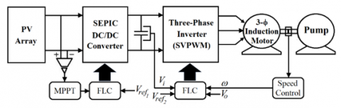
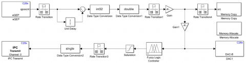
A block diagram of the proposed system is displayed in Figure 1. The design of the prototype mechanism is divided into two main parts. The first part involves the SEPIC DC/DC converter mechanism, which regulates the input voltage received from the PV array. The output of the SEPIC DC/DC converter serves as the voltage source for the three-phase inverter. This inverter is responsible for supplying voltage to the three-phase induction motor, which is coupled with water pumps for aquaculture and more.
Figure 1. Block diagram of the prototype mechanism
A block diagram of the proposed system is displayed in Figure 1. The design of the prototype mechanism is divided into two main parts. The first part involves the SEPIC DC/DC converter mechanism, which regulates the input voltage received from the PV array. The output of the SEPIC DC/DC converter serves as the voltage source for the three-phase inverter. This inverter is responsible for supplying voltage to the three-phase induction motor, which is coupled with water pumps for aquaculture and more.
The second part of the design is the control part, which includes the SEPIC DC/DC converter mechanism and the three-phase inverter mechanism. Fuzzy logic control (FLC) is used to independently control the high frequency switching of these mechanisms. The SEPIC DC/DC converter mechanism has fuzzy logic control conditions, including maximum power point tracking (MPPT) for solar light irradiation. This control condition regulates the voltage received from the PV array and compares it with the reference voltage in the configuration.
Similarly, the three-phase inverter mechanism also utilizes fuzzy logic control. The input voltage, DC link voltage, output voltage, and speed of the three-phase induction motor are compared with reference values. The input voltage of the three-phase inverter mechanism is filtered with an appropriate capacitor size to minimize ripples. Further details of the control mechanism will be provided in the next section.
The purpose of this discussion is to offer a thorough elucidation of the control techniques employed in the proposed study. In recent decades, several studies aiming at new solutions and control applications for these converters have been presented. One of the most commonly considered control methods for achieving a fixed voltage in such converters is fuzzy logic control. In this work, a new control application for high frequency switching, which is applied in photovoltaic systems, is proposed to increase voltage, reduce losses and accelerate system response.
3.1 Photovoltaic technology
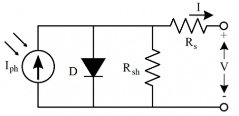
Photovoltaic cells produce direct current, which can be converted to alternating current through an inverter. However, a converter is necessary to increase the voltage and maintain a consistent level. The most commonly used converter mechanisms for direct current include the boost converter, buck converter, buck boost converter, and single-ended primary inductance converter (SEPIC). These converters are also utilized for connecting a photovoltaic system to the grid through an inverter. Photovoltaic cell technologies can be classified into three generations. First-generation cells, also known as conventional c-Si solar cells, have an efficiency rate of approximately 15-20%. They are created by slicing a piece of crystalline silicon from a large ingot and processing it into a wafer. Second-generation cells, referred to as thin-film cells, are characterized by a layer of crystalline silicon on glass, stainless steel, or a similar substrate. These thin-film cells are much thinner, measuring in micrometers, than first-generation silicon cells, which are 100-350 micrometers thick. As a result, thin-film cells require less material, making them more cost-effective. They are also more flexible and lighter than first-generation cells. However, their efficiency is lower, at approximately 10-12%. The efficiency of solar panels can be improved by incorporating multiple layers of photovoltaic cells in a single panel. These multijunction cells are commonly used in satellite environments and can achieve efficiencies exceeding 40%. It is important to test the efficiency of newly developed solar cells under standardized conditions known as 'STC' or 'Standard Test Conditions'. These conditions included a light spectrum with an air mass of 1.5, a radiation intensity of 1 kW/m², and a cell temperature of 25℃. The equivalent circuit of a single photovoltaic cell can be represented as shown in Figure 2.
Figure 2. Single-diode model
3.2 The single-ended primary inductance converter
The high-frequency switching control technique uses a chopping frequency that is ten times greater than the output voltage. Figure 3 illustrates the utilization of fuzzy logic control in high-frequency switching control. High-frequency switching control with fuzzy logic control consists of two inner current control loops and one outer voltage control loop. The input current feedback loop is used to control the inductor current. The two high-frequency duty cycle signals, Dhigh and DLow, are determined by a comparator to regulate the inductor current between the reference levels $i_{\max }^*$ and $i_{\min }^*$.
These two reference levels are used to calculate the value of the input current error. The controller output of the maximum power point tracking will change as the solar radiation varies throughout the day. The duty cycle d high will be updated and determined by the input irradiance level and output voltage. Additionally, the duty cycle DLow is found by subtracting both Dhigh and the controller output. All intermediate variables of the converter equations, which have a direct impact on the output voltage, are used as the inputs of the fuzzy logic controller.
A simulation of the SEPIC DC/DC converter under fuzzy logic control was performed. The input and intermediate variables were defined, and the output of the fuzzy controller was derived. For the three-phase inverter, a high-frequency switching control scheme is applied to regulate the output voltage. In principle, the implemented control strategy of the high-frequency switching control with fuzzy logic control in a three-phase inverter is quite similar to the fuzzy logic control in the SEPIC DC/DC converter, which has voltage control loops, and the output voltages are regulated by using triple component injection. The given simulation validity ensures that the designed control methods work perfectly under different conditions, such as sudden changes in the reference level and input irradiance. Additionally, the output voltage levels are well regulated, and the inverter can drive the motors efficiently by using high-frequency switching control and fuzzy logic control. Based on the simulation and analysis, it is evident that utilizing high-frequency switching control along with fuzzy logic control in a three-phase inverter yields a prompt response during abrupt changes in the reference level, as well as a robust tolerance toward fluctuations in both the input voltage and load. Finally, both a high-power factor and high efficiency can be achieved, as evidenced by the simulation results.
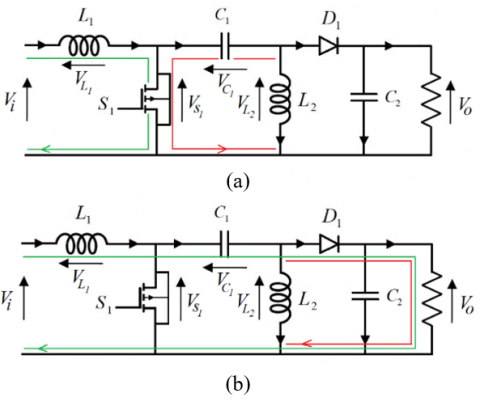
Figure 3. Fundamental principles of the SEPIC operation
Nonetheless, the desired outcome will be the voltage produced by the ideal SEPIC converter.
$V_o=\frac{D \times V_i}{1-D}$ (1)
Nonetheless, this equation does not consider any losses occurring as a result of elements in the circuit, such as voltage drop bracketing diodes (VD).
$V_o+V_D=\frac{D \times V_i}{1-D}$ (2)
Eq. (2) is derived, resulting in the representation of the duty cycle.
$D=\frac{V_o+V_D}{V_i+V_o+V_D}$ (3)
Nonetheless, the highest duty cycle is observed when the input voltage reaches its lowest value.
In theory, a larger inductor is more effective at reducing ripples. Conversely, the cost of larger inductors is greater, and they also result in increased internal resistance. This increased resistance negatively impacts the efficiency of the converter. To achieve the optimum converter design, it is crucial to select an inductor of sufficient size to maintain an acceptable voltage, ripple, and current. Therefore, the equation utilized for designing the inductor is essential.
In Eq. (4), $V_{i \min }$ represents the minimum input voltage, $D_{\max }$ signifies the maximum duty cycle, $\Delta i_{o \text { max }}$ denotes the maximum rate of change of the output current, and $f_{s w}$ represents the frequency utilized for electronic switches.
$L=\frac{V_{i \min }\left(D_{\max }\right)}{\Delta i_{o \max } f_{s w}}$ (4)
3.3 Implementation of fuzzy logic control in SEPIC DC/DC converter
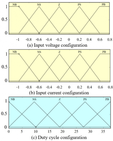
The peak current mode control algorithm, coupled with fuzzy logic control, was developed for the purpose of regulating the output of the SEPIC converter. The configuration and strategy for the fuzzy logic controller (FLC) in the SEPIC converter have been thoroughly discussed and designed. A hybrid -type fuzzy controller, equipped with two inputs and one output, is employed to regulate the output voltage [29-31]. The programming of the fuzzy logic controller is achieved using the advanced programming features within the TMS320F28379D microcontrollers. These microcontrollers are digital signal processors that operate at an impressive speed of 1 gigahertz. Additionally, they include a variety of internal and external I/O ports, allowing versatility in different fuzzy logic circuit applications. This advanced programming feature empowers the fuzzy logic controller to effectively handle noise, while providing a swift response to changes in data and maintaining a stable output without significant overshoot. The controller programs were successfully downloaded into the TMS320F28379D microcontrollers, and the SEPIC converter was tested by supplying non active power from the system. The converter has demonstrated excellent control over the power sourced from the photovoltaic panel. Furthermore, the TMS320F28379D microcontrollers have displayed the ability to adapt to noise and changes in system inputs, allowing for manipulation of the output voltage waveform without significant disturbances. By comparing fuzzy logic control and peak current mode control, it was determined that the SEPIC converter yields a favorable transient response and steady- state response. Despite the introduction of a large disturbance during fuzzy logic control, the output voltage remains well- regulated. This is due to the three membership functions of each input covering the entire range of the input voltage, enabling the fuzzy controller to manipulate the input without encountering any significant issues. Moreover, when power is supplied from the photovoltaic panel, the fuzzy logic- controlled SEPIC converter exhibits commendable performance in terms of the step response, settling time, rise time, and maximum peak overshoot. In the case of uncertain conditions, the logic algorithm for regulating the duty cycle can be classified into five variables: NB (negative big), NS (negative small), ZE (zero), PS (positive small), and PB (positive big). Furthermore, the control of the SEPIC converter relies on the fundamental conditions for FLC control, specifically the control of photovoltaic peak power point tracking, which entails voltage and current input, as well as duty cycle output, as demonstrated in Figure 4 [32].
The implementation of fuzzy logic control in the SEPIC DC/DC converter in this study defines a 5×5 member function for input errors to provide relatively accurate data with relatively small error results, as shown in Table 1.
Figure 4. Control of the fundamental parameters of fuzzy logic
Table 1. Rule base
|
DEE |
NB |
NS |
ZE |
PS |
PB |
|
DNB |
H |
H |
H |
MH |
M |
|
DNS |
H |
H |
MH |
MH |
LM |
|
DZE |
H |
MH |
MH |
LM |
LM |
|
DPS |
MH |
MH |
LM |
LM |
L |
|
DPB |
M |
LM |
L |
L |
L |
However, the parameter configuration method for controlling the DC/DC SEPIC converter with FLC defines the configuration conditions for the relationship between the input voltage and current and duty, as shown in Table 2.
Table 2. Parameter configuration
|
Parameter |
Specifications |
|
Input voltage (V) |
50-200 |
|
Input current (A) |
0-10 |
|
Duty cycle (%) |
0-75 |
The configuration process of DC/DC converter control with FLC is as follows: The input voltage from the photovoltaic configuration control voltage is in the range of 50-200 V, which will vary according to the duty cycle in the range of 0-75%. The current supplied to the load (inverter) is proportional to the input voltage relationship, which is controlled by comparison with the configured reference voltage.
To evaluate the precision of the fuzzy logic algorithm in controlling the generated SEPIC DC/DC converter mechanism, this study was assessed through mathematical simulation equations performed with the MATLAB/Simulink program. A test schematic, as depicted in Figure 5, was used for this purpose.
Figure 5. Demonstration of SEPIC
3.4 Implementation of fuzzy logic control in a three- phase inverter
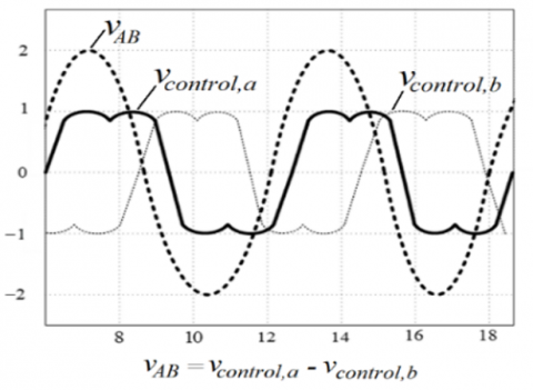
Initially, the discrepancy in phase currents is determined by evaluating the variance between the designated currents and the actual currents. Subsequently, this discrepancy and its rate of change over time are fuzzified using Gaussian membership functions, which contain instructions on how to rectify the current phase angles and averages for pulse width modulation (PWM) signals. These signals are then utilized to compute the ON and OFF durations for each of the six switches in the three-phase inverter, effectively rectifying the discrepancies to uphold superior performance. This subject matter delineates a configuration for a three-phase inverter employed in a three-phase motor drive. The purpose of this configuration is to attain substantial torque and power output through the utilization of space vector pulse width modulation (SVPWM). This technique governs the voltage of every phase connected to the positive or negative bus, which is divided into eight states. Nonetheless, these eight states serve as a means of intensifying the voltage between the line-to-line, which constitutes the fundamental frequency in a three-phase inverter system. This fundamental frequency dictates that the modulation of the phase control signals need not be in the form of a sinusoidal waveform; rather, the voltage disparity between the line and line must adhere to a sine waveform and possess a distinct phase angle of 120 degrees [33, 34].
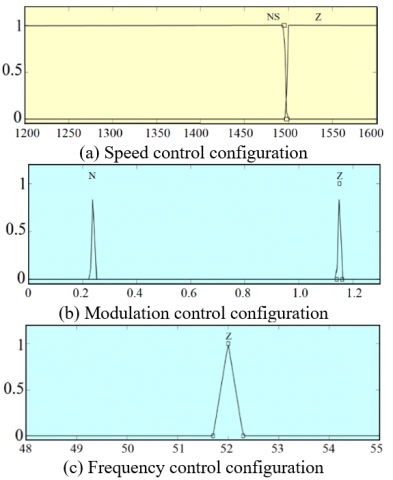
Figure 6 illustrates the waveforms controlling phase A and phase B, along with the line-to-line voltage waveforms. However, only the line-to-line voltage difference is shown in this instance. Similarly, for modulation control implemented through fuzzy logic control, two conditions must be met: modulation control versus frequency control. FLC control determines the output conditions of the three-phase inverter, which powers a three-phase induction motor. This condition necessitates real-time speed detection of the motor to define the six modulation and switching frequency conditions of the power electronics (IGBT or MOSFET) utilized in the three-phase inverters. However, FLC modulation and frequency control entail the application of conditional divisions, as demonstrated in Figure 7.
According to Figure 7, the conditions can be explained in the following manner: Condition 1 indicates that if there is a negative change in motor speed (N), the modulation index will be within the range of zero (Z), and the frequency will also be within the range of zero (Z). Similarly, condition two indicates that if there is no change in motor speed (Z), the modulation index will be in the negative range (N), and the frequency value will be in the zero range (Z). However, the subsequent section of the study focuses on conducting experiments and evaluating the results of the prototype mechanism through a comparative analysis.
Figure 6. The modulation waveforms of the SVPWM
Figure 7. Control configuration of a three-phase inverter using the SVPWM
Similarly, for the fuzzy logic control application with a three-phase inverter, a 2×2 member function is defined, which provides 4 control conditions. From the control conditions, there is a relatively small error in the input, which consists of accurate and sufficient to control the device. The six switches can configure the functions, as shown in Table 3.
Table 3. Rule base
|
DEE |
NN |
NZ |
|
DNN |
MH |
MH |
|
DNZ |
MM |
LM |
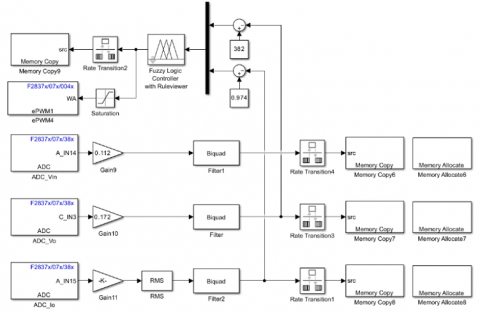
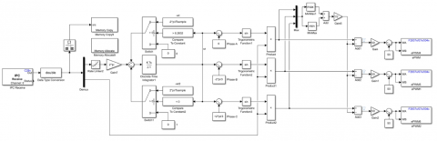
Equally, consequently, to verify the soundness of the control principle, it was assessed using mathematical simulation equations in MATLAB/Simulink software, following the test diagram illustrated in Figure 8 and Figure 9.
In the following section, the creation mechanism is evaluated by aligning the outcomes acquired through the MATLAB/Simulink simulation. This evaluation included using a suitable setup for the desired objective with TMS320F28379D microcontrollers.
Figure 8. Control of the SVPWM
Figure 9. Control of the three-phase motor speed
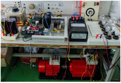
Figure 10 shows the mechanisms and prototypes designed for experimentation and evaluation.
Figure 10. Mechanisms and prototypes created
The instant evaluation of the results is determined by various dynamic scenarios, as specified in Table 4.
The assessment of the experiment is divided into two parts: the first focuses on the voltage regulation of the SEPIC DC/DC converter, while the second concentrates on the control of the three-phase induction motor. The following sections present an evaluation and discussion of these aspects.
Table 4. Configuration specifications
|
Details |
Specifications |
|
Three-phase induction motor (HP) |
1.34 |
|
Irradiation level (W/m2) |
1000 |
|
Input voltage (V) |
250-330 |
|
Output voltage (V) |
380 |
The evaluation of the SEPIC DC/DC converter and three-phase inverter mechanism for the use of fuzzy logic control was conducted using MATLAB/Simulink software. This control method utilizes conditions and tools provided in the MATLAB/Simulink program library and is compatible with TMS320F28379D microcontrollers. The evaluation and analysis of the experiment are presented as follows.
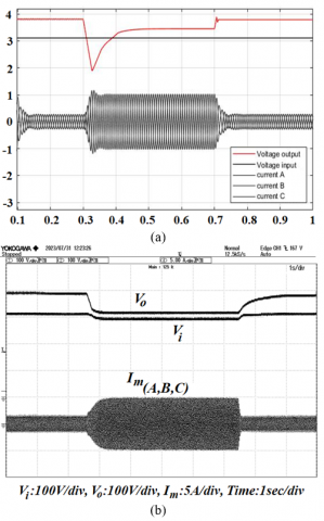
Figures 11 (a) and (b) simulation and evaluation of fuzzy logic control for high-frequency switching in SEPIC DC / DC photovoltaic converters and three-phase inverters controlled by the SVPWM method in the state of a three-phase induction motor coupled with a load (pump). Under this condition, the performance of the created mechanism is simulated and evaluated, as well as the system that does not have the fuzzy logic control algorithm. The simulation and evaluation, as shown in Figure 11 (a), using the tools in the MATLAB/Simulink program library show that the input voltage configured according to the conditions results in the output voltage ripple of the absorbing power during the start of the three-phase induction motor and on load. Similarly, if the current/phase of the three phases of the induction motor is considered, the current waveform is consistent and correlated with the output voltage waveform. However, if the test is considered in the no-load condition, the output voltage is slightly absorbed power again and enters the three-phase induction motor operating under normal conditions.
Figure 11 (b) comparing the performance evaluation results of the created mechanism with the simulation results, it is found that if the photovoltaic has the intended voltage but the effect due to irradiation and temperature causes the maximum power point of the power supply to the SEPIC DC/DC converters and three-phase inverters to decrease in performance, causing the input voltage and output voltage of the mechanism to decrease. Similarly, the output voltage is reduced compared to that of the input due to the absorbing power of the three-phase inverters supplied to the three-phase induction motor. At the same time, for the three-phase induction load supply motor, the absorbing power causes the current of the three-phase induction motor for the on load to lose more power than in the simulation because the simulation cannot cause a dynamic condition. However, if we consider the overall picture, it can be unuttered and conclude that the simulation results and the evaluation results of the generated mechanism are consistent, so the results are confirmed and reliable.
Figure 11. Simulation and evaluation of the operation of the SEPIC DC/DC converter in the uncontrolled state of fuzzy logic
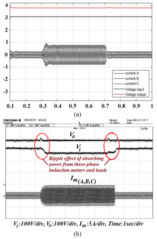
Figures 12 (a) and (b) show simulations and evaluations of the SEPIC DC/DC converter controlled by fuzzy logic and the three-phase inverter controlled by the created SVPWM method created. Figure 12 (a) shows the simulation with a MATLAB / Simulink control program with fuzzy logic and an SVPWM. Based on the simulation with the configuration input voltage, output voltage, and modulation ratio (% duty), under the maximum power point tracking of the photovoltaic system, the voltage control of the SEPIC DC/DC converter controlled by fuzzy logic can be effectively controlled. Similarly, when supplying voltage to a three-phase inverter, the SVPWM method can better control the power supply to the three-phase induction and load than can unregulated.
Figure 12 (b) is an evaluation of the performance of the created mechanism, and it is found that the energy absorption while inducing three phases in the load, the SEPIC DC/DC converter, and the three-phase inverter can control the power supply according to the purpose of the configuration. However, if the simulation and evaluation are considered in a general way, the performance of the results is consistent.
Figure 12. Simulation and evaluation of the operation of the SEPIC DC/DC converter in the uncontrolled state of fuzzy logic
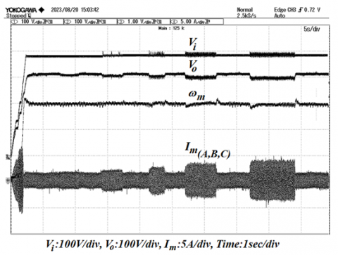
Figure 13 shows an evaluation of the performance of the SEPIC DC/DC converter mechanism controlled by fuzzy logic and a three-phase inverter controlled by the SVPWM method. The configuration allows the three-phase induction motor to be loaded in continuous steps to evaluate the durability of the created mechanism. The evaluation revealed that the mechanism is able to respond well to the changes that occur. However, if the input voltage, output voltage, speed, and current of each phase of three-phase induction are considered, the response results of the measured parameters are consistent and relative. Similarly, on the basis of the evaluation of the mechanism at different times of photovoltaic exposure from the sun, it was found that maximum power point tracking is the main factor in supplying power to the created mechanism. Therefore, the overall control of the power of the mechanism depends on the factors and effects of irradiation and temperature on the photovoltaic system. Similarly, simulations of maximum power point tracking control with other algorithms of SEPIC DC/DC converters controlled by fuzzy logic, including Perturb and Observe (P&O), incremental conductance (INC), and genetic (GA), show that each algorithm has different limitations depending on the application conditions. However, the SEPIC DC/DC converter controlled by the fuzzy logic method has been found to have more distinctiveness and advantages and can provide more fine-grained control conditions. The need for high resolution can create more fuzzy conditions and rules, making the control of the voltage change of the SEPIC DC/DC converter even more efficient.
Figure 13. Overview of the operation of the SEPIC DC/DC converter mechanism and the three-phase inverter
Constant control of the output voltage of the three-phase inverter using the SVPWM method. The outstanding feature of this SVPWM control method, which uses the principle of voltage control on the DQ frame axis in real time, is that it connects signals from the controller model to MATLAB/Simulink programs through digital signal processing boards TMS320F28379D microcontrollers faster than conventional classical methods. The SVPWM control method can control the stability of the output voltage faster and more efficiently than can the conventional classical method. Therefore, the three-phase inverter using the SVPWM method created for this research has a size and rating that can withstand changes of more than 10% from the rated input voltage supplied by the SEPIC DC/DC converter.
Similarly, a comparison of the SVPWM control method was performed by connecting signals from the controller model in the MATLAB/Simulink program via the DSPACE 1104 digital signal processing board to the signal connection from the controller model in the MATLAB/Simulink program through the digital signal processing board TMS320F28379D microcontrollers. Based on the control of the created mechanism, the response performance of the TMS320F28379D microcontrollers can be controlled under real-time conditions with a lower error percentage than that of the digital signal processing boards. DSPACE 1104. The comparison of the SVPWM control methods of these two digital signal processing boards is only one part. However, researchers interested in this SVPWM control method should consider the DQ frame-axis conversion principle, which is the main process of responding to configuration in conjunction with connecting signals from the control model in MATLAB/Simulink.
Fuzzy logic control for high-frequency switching in photovoltaic SEPIC DC/DC converters and three-phase inverters is developed and created using the SVPWM method in the driving state of three-phase induction motors coupled with loads (pumps). To ensure real-time control of the prototype mechanism using the fuzzy logic control of the SEPIC DC/DC converter, it can handle high-frequency switching devices. There are three parameters for the configuration of the SEPIC DC/DC converter mechanism, including the input voltage, input current, and modulation rate (% duty cycle) of the mechanism. According to the evaluation, Fuzzy Logic Control for High-Frequency Switching in Photovoltaic SEPIC DC/DC Converters can effectively control the maximum power point tracking operation according to the configuration conditions set for the purpose, even if there are irradiation and temperature changes caused by photovoltaics. The results of a simulation evaluation with the MATLAB/Simulink program, are compared with those of a prototype mechanism, which confirms the validity of the principles and methods and that the proposed method is reliable.
Similarly, the fuzzy logic control of a three-phase inverter with the SVPWM method to control the high-frequency switching of power electronics (IGBT) according to the given configuration conditions revealed that the control of the output voltage stability of a three-phase inverter with a DQ frame in real time is more prominent than that of the conventional classical method. Connecting signals from a simulation of a controller in a MATLAB/Simulink program via a digital signal processing board TMS320F28379D microcontroller can be controlled more quickly than can other classical methods. The configuration control of the three-phase inverter can effectively control the speed of the three-phase induction motor drive when loaded, as shown and described above.
However, researchers interested in this SVPWM control method should consider the DQ frame-axis conversion principle, which is the main process of responding to the configuration together with connecting signals from the controller model in the MATLAB/Simulink program of the created three-phase inverter. Similarly, if you are interested in the development mechanism of SEPIC DC/DC converters, the conditions and rules of fuzzy methods should be improved to be more precise, which will make the control of the output voltage stability of SEPIC DC/DC converters using high-frequency switching more efficient.
The researchers and working group express their gratitude to Dhonburi Rajabhat University, Thailand, for its support in providing laboratories and research instruments, which enabled them to successfully achieve their objectives.
[1] Hosseini, S.E., Wahid, M.A. (2020). Hydrogen from solar energy, a clean energy carrier from a sustainable source of energy. International Journal of Energy Research, 44(6): 4110-4131. https://doi.org/10.1002/er.4930
[2] Obaideen, K., AlMallahi, M.N., Alami, A.H., Ramadan, M., Abdelkareem, M.A., Shehata, N., Olabi, A.G. (2021). On the contribution of solar energy to sustainable developments goals: Case study on Mohammed bin Rashid Al Maktoum Solar Park. International Journal of Thermofluids, 12, 1-14. https://doi.org/10.1016/j.ijft.2021.100123
[3] Kanna, I.V., Demir, D. (2020). Solar research–A review and recommendations for the most important supplier of energy for the earth with solar systems. International Journal of Ambient Energy, 41(8): 962-968. https://doi.org/10.1080/01430750.2018.1472658
[4] Pandey, A.K., Kumar, R.R., Kalidasan, B., Laghari, I.A., Samykano, M., Kothari, R., Abusorrah, A.M., Sharma , K., Tyagi, V.V. (2021). Utilization of solar energy for wastewater treatment: Challenges and progressive research trends. Journal of Environmental Management, 297: 113300. https://doi.org/10.1016/j.jenvman.2021.113300
[5] Tafti, H.D., Konstantinou, G., Townsend, C.D., Farivar, G.G., Sangwongwanich, A., Yang, Y., Pou, J., Blaabjerg, F. (2020). Extended functionalities of photovoltaic systems with flexible power point tracking: Recent advances. IEEE Transactions on Power Electronics, 35(9): 9342-9356. https://doi.org/10.1109/TPEL.2020.2970447
[6] Aygül, K., Cikan, M., Demirdelen, T., Tumay, M. (2023). Butterfly optimization algorithm based maximum power point tracking of photovoltaic systems under partial shading condition. Energy Sources, Part A: Recovery, Utilization, and Environmental Effects, 45(3): 8337-8355. https://doi.org/10.1080/15567036.2019.1677818
[7] Mishra, D.P., Senapati, R., Salkuti, S.R. (2022). Comparison of DC-DC converters for solar power conversion system. Indonesian Journal of Electrical Engineering and Computer Science, 26(2): 648-655. https://doi.org/10.11591/ijeecs.v26.i2.pp648-655
[8] Uthirasamy, R., Chinnaiyan, V.K., Vishnukumar, S., Karthick, A., Mohanavel, V., Subramaniam, U., Muhibbullah, M. (2022). Design of boosted multilevel DC-DC converter for solar photovoltaic system. International Journal of Photoenergy, 2022(1): 1648474. https://doi.org/10.1155/2022/1648474
[9] Raj, A., Praveen, R.P. (2022). Highly efficient DC-DC boost converter implemented with improved MPPT algorithm for utility level photovoltaic applications. Ain Shams Engineering Journal, 13(3): 101617. https://doi.org/10.1016/j.asej.2021.10.012
[10] Khan, R.A., Liu, H.D., Lin, C.H., Lu, S.D., Yang, S.J., Sarwar, A. (2023). A novel high-voltage gain step-up DC-DC converter with maximum power point tracker for solar photovoltaic systems. Processes, 11(4): 1087. https://doi.org/10.3390/pr11041087
[11] Sutikno, T., Purnama, H.S., Aprilianto, R.A., Jusoh, A., Widodo, N.S., Santosa, B. (2022). Modernisation of DC-DC converter topologies for solar energy harvesting applications: A review. Indonesia Journal of Electrical Engineering and Computer Science, 28(3): 1845-1872. https://doi.org/10.11591/ijeecs.v28.i3.pp1845-1872
[12] Shams, I., Mekhilef, S., Tey, K.S. (2020). Maximum power point tracking using modified butterfly optimization algorithm for partial shading, uniform shading, and fast varying load conditions. IEEE Transactions on Power Electronics, 36(5): 5569-5581. https://doi.org// 10.1109/TPEL.2020.3029607
[13] Pervez, I., Shams, I., Mekhilef, S., Sarwar, A., Tariq, M., Alamri, B. (2021). Most valuable player algorithm based maximum power point tracking for a partially shaded PV generation system. IEEE Transactions on Sustainable Energy, 12(4): 1876-1890. https://doi.org/10.1109/TSTE.2021.3069262
[14] Ravindranath Tagore, Y., Rajani, K., Anuradha, K. (2022). Dynamic analysis of solar powered two-stage DC-DC converter with MPPT and voltage regulation. International Journal of Dynamics and Control, 10(6): 1745-1759. https://doi.org/10.1007/s40435-022-00930-8
[15] Baba, A.O., Liu, G., Chen, X. (2020). Classification and evaluation review of maximum power point tracking methods. Sustainable Futures, 2: 100020. https://doi.org/10.1016/j.sftr.2020.100020
[16] Pande, J., Nasikkar, P., Kotecha, K., Varadarajan, V. (2021). A review of maximum power point tracking algorithms for wind energy conversion systems. Journal of Marine Science and Engineering, 9(11): 1187. https://doi.org/10.3390/jmse9111187
[17] Kumar, G.A., Shivashankar. (2022). Optimal power point tracking of solar and wind energy in a hybrid wind solar energy system. International Journal of Energy and Environmental Engineering, 13(1): 77-103. https://doi.org/10.1007/s40095-021-00399-9
[18] Eltamaly, A.M., Al-Saud, M.S., Abokhalil, A.G. (2020). A novel bat algorithm strategy for maximum power point tracker of photovoltaic energy systems under dynamic partial shading. IEEE Access, 8: 10048-10060. https://doi.org/10.1109/ACCESS.2020.2964759
[19] Kumar, S., Saket, R.K., Dheer, D.K., Holm‐Nielsen, J.B., Sanjeevikumar, P. (2020). Reliability enhancement of electrical power system including impacts of renewable energy sources: A comprehensive review. IET Generation, Transmission & Distribution, 14(10): 1799-1815. https://doi.org/10.1049/iet-gtd.2019.1402
[20] E Husin, H., Zaki, M. (2021). A critical review of the integration of renewable energy sources with various technologies. Protection and Control of Modern Power Systems, 6(1): 1-18. https://doi.org/10.1186/s41601-021-00181-3
[21] Bagherian, M.A., Mehranzamir, K. (2020). A comprehensive review on renewable energy integration for combined heat and power production. Energy Conversion and Management, 224: 113454. https://doi.org/10.1016/j.enconman.2020.113454
[22] Sinsel, S.R., Riemke, R.L., Hoffmann, V.H. (2020). Challenges and solution technologies for the integration of variable renewable energy sources—A review. Renewable Energy, 145: 2271-2285. https://doi.org/10.1016/j.renene.2019.06.147
[23] Alam, M.S., Al-Ismail, F.S., Salem, A., Abido, M.A. (2020). High-level penetration of renewable energy sources into grid utility: Challenges and solutions. IEEE Access, 8: 190277-190299. https://doi.org/10.1109/ACCESS.2020.3031481
[24] Hamid, A.K., Mbungu, N.T., Elnady, A., Bansal, R.C., Ismail, A.A., AlShabi, M.A. (2023). A systematic review of grid-connected photovoltaic and photovoltaic/thermal systems: Benefits, challenges and mitigation. Energy & Environment, 34(7): 2775-2814. http://dx.doi.org/10.1177/0958305X221117617
[25] Basit, M.A., Dilshad, S., Badar, R., Sami ur Rehman, S.M. (2020). Limitations, challenges, and solution approaches in grid‐connected renewable energy systems. International Journal of Energy Research, 44(6): 4132-4162. https://doi.org/10.1002/er.5033
[26] Mohamad, F., Teh, J., Lai, C.M. (2021). Optimum allocation of battery energy storage systems for power grid enhanced with solar energy. Energy, 223: 120105. https://doi.org/10.1016/j.energy.2021.120105
[27] Bughneda, A., Salem, M., Richelli, A., Ishak, D., Alatai, S. (2021). Review of multilevel inverters for PV energy system applications. Energies, 14(6): 1585. https://doi.org/10.3390/en14061585
[28] Al-Shahri, O.A., Ismail, F.B., Hannan, M.A., Lipu, M.H., Al-Shetwi, A.Q., Begum, R.A., Al-Muhsen, N.F., Soujeri, E. (2021). Solar photovoltaic energy optimization methods, challenges and issues: A comprehensive review. Journal of Cleaner Production, 284: 125465. https://doi.org/10.1016/j.jclepro.2020.125465
[29] Zangeneh, M., Aghajari, E., Forouzanfar, M. (2022). Design and implementation of an intelligent multi-input multi output Sugeno fuzzy logic controller for managing energy resources in a hybrid renewable energy power system based on Arduino boards. Soft Computing, 26: 1459-1473. https://doi.org/10.1007/s00500-021-06288-x
[30] Phan, D., Bab-Hadiashar, A., Fayyazi, M., Hoseinnezhad, R., Jazar, R.N., Khayyam, H. (2021). Interval type 2 fuzzy logic control for energy management of hybrid electric autonomous vehicles. IEEE Transactions on Intelligent Vehicles, 6(2): 210-220. https://doi.org// 10.1109/TIV.2020.3011954
[31] Pradhan, P.C., Sahu, R.K., Panda, S. (2021). Analysis of hybrid fuzzy logic control based PID through the filter for frequency regulation of electrical power system with real-time simulation. Journal of Control, Automation and Electrical Systems, 32(4): 439-457. https://doi.org/10.1007/s40313-020-00684-8
[32] Chaithanakulwat, A., Thungsuk, N., Savangboon, T., Ngao-Ngam, S., Kanharin, P., Kanjak, N., Tanaram, T. (2023). A comparison of the response and voltage regulation performance of the single-channel DC/DC boost converter circuit with artificial neural networks, fuzzy logic and PID controllers. Journal Européen des Systèmes Automatisés, 56(1): 77-87. https://doi.org/10.18280/jesa.560111
[33] Ghaderi, D., Padmanaban, S., Maroti, P.K., Papari, B., Holm-Nielsen, J.B. (2020). Design and implementation of an improved sinusoidal controller for a two-phase enhanced impedance source boost inverter. Computers & Electrical Engineering, 83: 106575. https://doi.org/10.1016/j.compeleceng.2020.106575
[34] Chakir, F., El Magri, A., Lajouad, R., Kissaoui, M.H., Zeggaf, M.H. (2022). A new multilevel DC-AC converter topology with a reduced number of switches controlled by the multi carrier sinusoidal PWM technique. In 2022 2nd International Conference on Innovative Research in Applied Science, Engineering and Technology (IRASET), Meknes, Morocco, 2022: 1-5. https://doi.org//10.1109/IRASET52964.2022.9738017