Ahmed Khalaf Hamoudi![]() | Luay Thamir Rasheed*
| Luay Thamir Rasheed*![]()
© 2024 The authors. This article is published by IIETA and is licensed under the CC BY 4.0 license (http://creativecommons.org/licenses/by/4.0/).
OPEN ACCESS
This study examines the effectiveness of an adaptive integral sliding mode controller (AISMC) for adjusting an electronic throttle valve's (ETV) angular position. An electronic throttle is a DC motor-driven valve that controls the flow of air into the engine in modern cars. Due to the nonlinear dynamical properties of electronic throttle systems, they are challenging to control using the conventional PID control technique. In the present investigation, an adaptive integral sliding mode control approach is recommended for controlling the ETV. First, the dynamical model of the electronic throttle is utilized to create an integral sliding mode controller (ISMC). The switching control term and the equivalent control term makes up the ISMC. The permissible minimum switching control term's gain is determined using the adaptive sliding mode control. The controller's chattering is reduced as a result. A computer simulation of the suggested control technique is then conducted, and the simulation results validate that the suggested control method has a sufficient degree of control performance. Regarding the transient features of the system, an analysis has been carried out to compare the effectiveness of the AISMC with alternative controllers. The MATLAB package's environment has been employed to implement the simulation.
electronic throttle valve, adaptive integral sliding mode controller, disturbance, parameters uncertainty, chattering
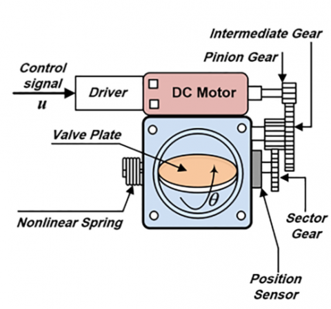
One of the most important components of an automobile engine is its throttle valve. During combustion process, the air-fuel ratio is adjusted by changing the valve plate's opening angle. In traditional car engines, the valve plate is directly controlled by the driver through a wire connection to the accelerator pedal. Classical technology does not take into consideration external and internal factors such as weather, road conditions, fuel efficiency, vehicle emissions, and fuel economy. This has a negative impact on the engine's overall efficiency and the accuracy of the car's system, particularly because the dynamics of the throttle valve are highly complex and nonlinear due to variable stiffness and mechanical hysteresis. In recent automotive technologies, the ETV has appeared to solve the problems caused by the previous era's conventional throttle valve [1, 2]. The ETV is seen in Figure 1 [2].
The components of the ETV as it is described in the study [2] are as follows: a position sensor, a nonlinear spring, a valve plate, a motor pinion gear, an intermediate gear, a sector gear, and a DC motor operated by a driver. The ETV basically acts as a DC motor-driven valve that regulates the quantity of air that enters the car's combustion system [1-5]. The mechanism for controlling of the engine control unit positions the electronics throttle valve using the reference opening angle. Throttling angle, which modifies the air mass flow rate to the engine port, is the primary engine control input that meets the required characteristics [6-10].
Figure 1. The ETV schematic diagram [2]
In present vehicles, the electronic throttle has become more and more prevalent. in an effort to lower emissions, improve fuel economy, and improve driver comfort. The electronic throttle exhibits a high degree of parameter uncertainty and nonlinearity. It is difficult to get an acceptable control performance when utilizing the conventional PID control approach because of the strong nonlinear feature and parameters uncertainty in the electronic throttle. For controlling such controlled plants with high nonlinear features and parameter uncertainty, backstepping controller and sliding mode control are dependable control techniques. The Backstepping controller performs well and has good qualities for controlling the ETV's position [11-16]. Because the sliding-mode control may asymptotically stabilize the system, it has been widely used in real-world applications [17-22].
The control law in the studies [23, 24] is the twisting algorithm based on second order sliding mode control for the control of an ETV. Additionally, in the study [21], the electronic throttle was regulated using fuzzy sliding-mode control, in which the gain of the switching control term was identified using the fuzzy logic system. As a result, the controller's chatting is suppressed. In the study [22], the sliding mode control is implemented using neural networks to adjust the angular position of the electronic throttle's valve. Some researchers employ Observer based Sliding-Mode Control to regulate the opening of the ETV systems [23].
Higher Order Sliding-Mode design and control of an electronic throttle control system were present in the studies [24, 25]. An idea for an adaptive sliding mode control mechanism has been outlined [26-30] to control the position of the ETV. Furthermore, integral sliding mode control was implemented in certain works to control ETV's angular position [31, 32]. This research suggests developing an adaptive integral sliding mode control approach to control the position of the ETV. The nominal control part and the discontinuous control part make up the suggested controller.
The ETV's dynamical model serves as the foundation for the nominal control part's design. On the other hand, the adaptive sliding mode control serves to identify the discontinuous control component. The adaptive sliding mode control, to put it simply, calculates the switching gain. The adaptive-integral sliding-mode control approach provided here can reduce chattering with little time settling period. Lastly, a computer simulation executes using MATLAB programming and Simulink, and the results confirm that the recommended control technique works.
The ETV mathematical models are expressed [16]:
$\ddot{\theta}=-a_1 \theta-a_2 \dot{\theta}+b_1 \mathrm{u}+w$ (1)
where, $w$ represent the disturbance and the parameters uncertainty.
If one establishes $x_1=\theta, x_2=\dot{\theta}$, and $y=x_1$, then the representation of the state space of the variables can be expressed below [16]:
$\dot{x_1}=x_2$ (2)
$\dot{x_2}=-a_1 x_1-a_2 x_2+b_1 u+w$ (3)
In matrix form Eqs. (2) and (3) becomes
$\left[\begin{array}{l}\dot{x}_1 \\ \dot{x}_2\end{array}\right]=\left[\begin{array}{cc}0 & 1 \\ -a_1 & -a_2\end{array}\right]\left[\begin{array}{l}x_1 \\ x_2\end{array}\right]+\left[\begin{array}{c}0 \\ b_1\end{array}\right] u+\left[\begin{array}{c}0 \\ w\end{array}\right]$ (4)
And the output can be represented as below:
$y=\left[\begin{array}{ll}1 & 0\end{array}\right]\left[\begin{array}{l}x_1 \\ x_2\end{array}\right]$ (5)
where,
$\begin{aligned} & a_1=2.9245 \times 10^{-11}, a_2=2.9275 \times 10^{-11} \\ & b_1=0.3139 \text {, and } w=-1.8207\end{aligned}$
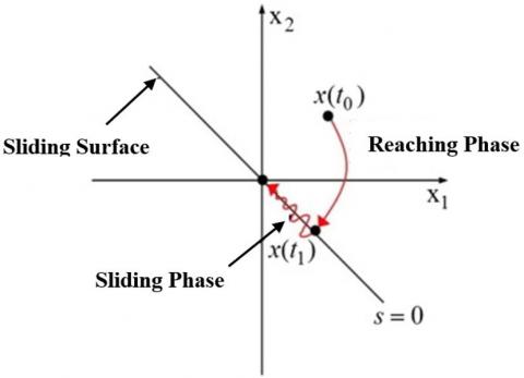
A well-liked methodology for developing a dependable controller technique in contemporary control systems is the SMC. This type of controller is composed of two phases, the reaching phase and the sliding phase [27]. Figure 2 below shows these two phases:
Figure 2. The two phases of classical sliding mode [27]
In the reaching phase, the state trajectory will begin from any initial position and then oriented toward the switching surface S=0; hence, the sliding phase will be started at this instant as shown in Figure 2 [33]. In the sliding phase, as demonstrated in Figure 2, the state trajectory is required to remain on the switching surface and travel along it until it reaches the origin in a finite amount of time [33].
The control action in SMC is expressed as below:
$u=u_n+u_{d i s}$ (6)
where, $u_{\text {dis }}$ represents the discontinuous control portion and $u_n$ represents the nominal control part. The definition of the discontinuous control portion, $u_{\text {dis }}$, is as follows [27]:
$u_{d i s}=-k(t) \operatorname{sign}(s)$ (7)
where, $k(t)$ is a positive-valued constant. By inserting Eq. (7) in (6), the control law can be rewritten as:
$u=u_n-k(t) \operatorname{sign}(s)$ (8)
One of the most significant issues with the sliding mode control is the chattering phenomenon, which is brought on by a zigzag motion in the output along the sliding surface. Since chattering phenomenon excite the un-modeled dynamics of mechanical systems, it is an undesired attribute. The Chattering, which is undesirable characteristic, is occures becauses of using the $\operatorname{sign}(s)$ function in discontinuous control part [33].
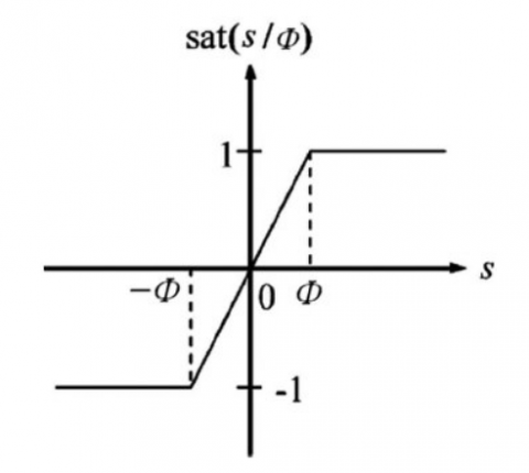
To decrease chattering, the saturation function, which is shown in Figure 3, is used in place of the signum function in Eq. (8). Eq. (8) will therefore look like this:
$u=u_n-k(t) \operatorname{sat}(s)$ (9)
where, $s$ represents the sliding surface and it can be characterized as:
$s=\lambda e+\dot{e}$ (10)
where, $\lambda$ is a positive-valued constant parameter. To keep things simple, we'll suppose that $\lambda=1$.
Let $x_1=e$ and $x_2=\dot{e}$, then Eq. (10) will be as below:
$s=x_1+x_2$ (11)
Figure 3. The saturation function [27]
$\operatorname{sat}(s, \varphi)=\left\{\begin{array}{cl}\operatorname{sign}(s) & \text { if }|s|>\varphi \\ 1 & \text { if }|s| \leq \varphi\end{array}\right\}$ (12)
Hence, as shown in Figure 3, $\varphi$ is the thickness of the saturation function.
To create the AISMC design, two components of Eq. (6) are required. The two components of Eq. (6) are $u_n$ and $u_{\text {dis}}$. This controller's construction uses $u_n$ in the same way as an integral sliding mode controller (ISMC) [33]. On other hand, the discontinuous controller part, $u_{\text {dis }}$ is obtained in the same manner as an adaptive sliding mode controller (ASMC) is designed [27].
4.1 The design of $u_n$
Let the error and its derivatives are defined as below:
$z_1=e=\theta-\theta_d+0.095$ (13)
where, the value 0.095 is the offset value of ETV
$\theta=z_1+\theta_d-0.095$ (14)
and,
$z_2=\dot{e}=\dot{\theta}-\dot{\theta_d}$ (15)
$\dot{\theta}=z_2+\dot{\theta_d}$ (16)
substitute Eqs. (12) and (14) in Eq. (10) and for simplicity let $\lambda=1$. The Eq. (10) will be as below:
$s_0=z_1+z_2$ (17)
$z=-s_0 $ (18)
$s=s_0+z $ (19)
$\dot{z}_1=z_2$ (20)
$\ddot{z}_2=\ddot{\theta}-\ddot{\theta}_d=\ddot{e}$ (21)
$\ddot{\theta}-\ddot{\theta_d}-\ddot{e}=0$ (22)
Eq. (3) yields $\ddot{\theta}$ in the equation above, and $\ddot{e}$ is written [31]:
$\ddot{e}+c_1 e+c_2 \dot{e}=0$ (23)
$ \ddot{e}=-c_1 z_1-c_2 z_2$ (24)
Eqs. (3) and (21) can be substituted into Eq. (19) to get this outcome.
$\begin{gathered}-a_1\left(z_1+\theta_d-0.095\right)-a_2\left(z_2+\dot{\theta_d}\right)+b_1 u+ \\ w-\ddot{\theta_d}+c_1 z_1+c_2 z_2=0\end{gathered}$ (25)
And as a result, $u$ can be obtained from the last equation as below:
$\begin{gathered}u=\frac{1}{b_1}\left(a_1\left(z_1+\theta_d-0.095\right)+a_2\left(z_2+\dot{\theta_d}\right)-\right. \\ \left.w+\ddot{\theta_d}-c_1 z_1-c_2 z_2\right)\end{gathered}$ (26)
The last equation represents nominal control part $u_n$. Therefore, the last equation can rewrite as following:
$\begin{gathered}u_n=\frac{1}{b_1}\left(a_1\left(z_1+\theta_d-0.095\right)+a_2\left(z_2+\dot{\theta_d}\right)-\right. \\ \left.w+\ddot{\theta_d}-c_1 z_1-c_2 z_2\right)\end{gathered}$ (27)
4.2 The design of $u_{\text {dis }}$
The value of $k(t)$ in ASMC could be stated [27]:
$k(t)=\left\{\begin{array}{ccc}\mu & \text { if } & K_{\min }<\mu<K_{\max } \\ K_{\min } & \text { if } & \mu \leq K_{\min } \\ K_{\max } & \text { if } & \mu \geq K_{\max }\end{array}\right\}$ (28)
$\begin{array}{ll}\dot{k}(t) =\left\{\begin{array}{cl}\rho \cdot|s(x . t)| \cdot \operatorname{sign}(|s(x . t)|)-\epsilon) & \text { if } k>\mu \\ \mu & \text { if } k \leq \mu\end{array}\right\}\end{array}$ (29)
where, $\rho>0$ is used to raise or lower the value of $k(t), \epsilon>$ 0 is a very small value, and $K_{\min }$ and $K_{\max }$ are the minimum and maximum gain respectively that must be properly selected by the designer.
Finally, the complete equation of AISMC can be described by replacing Eqs. (9) and (27) in Eq. (6).
$\begin{gathered}u=\frac{1}{b_1}\left(a_1\left(z_1+\theta_d-0.095\right)+a_2\left(z_2+\dot{\theta_d}\right)-w+\right. \\ \left.\ddot{\theta}_{d^{-}}-c_1 z_1-c_2 z_2\right)-\mathrm{k}(\mathrm{x}) \operatorname{sat}(\mathrm{s})\end{gathered}$ (30)
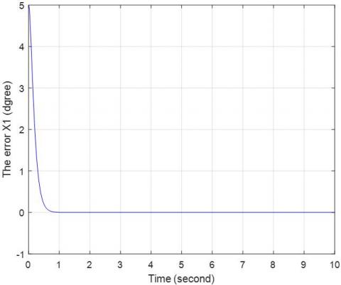
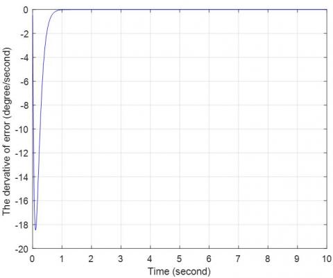
A computer is used to simulate the suggested controller with the ETV through the use of MATLAB programming. Figures 4 to 12 display the simulation's results. The intended angle is depicted with time in Figure 4. Figure 5 displays the actual angle over time. Figure 6 combined the desired and the actual angle with time to illustrate the variation between the two. Figures 7 and 8, respectively, show the error and the derivative of the error with time. These figures indicate that the tracking error is significantly smaller than that of the ASMBSC [16], as shown in Table 1. Conversely, Figure 9 shows the phase plane that occurs between the error and the error's derivative. The recommended controller's control action is depicted in Figure 10. This figure reveals that the control action is smooth and without sharp spikes and within the acceptable range of ±24 volts depending on the supply voltage of the DC motor of the ETV. Figure 11 shows a representation of the sliding surface. The main feature of the ISMC is that the sliding variable $s$ is equal to zero from the first instant which means that the system reaches the sliding surface from the first time of simulation. Lastly, Figure 12 plots the integral term $z$ and sliding variable $s$ against time.
Figure 4. The desired angle (degree) against time
Figure 5. The actual angle (degree) against time
Figure 6. The desired and actual angles with time (degree)
Figure 7. The error $x_1$ (degree) against time
Figure 8. The temporal derivative of errors $x_2$ (degree/second) against time
Figure 9. The phase plane that separates the error from the error derivative
Figure 10. The control measure (volt) against time
Figure 11. The sliding surface against time
Figure 12. The sliding variable $s$ and integral term $z$ plotted against time
Table 1. The controllers' tracking error
|
Time (Second) |
Tracking Error of AISMC (Degree) |
Tracking Error of ASMBSC (Degree) [16] |
|
0.8 |
0.192 |
-0.04 |
|
3 |
3.98×10⁻⁷ |
0 |
|
5 |
8.17×10⁻⁷ |
0.001 |
|
8 |
8.57×10⁻⁷ |
0 |
|
10 |
-1.24×10⁻⁶ |
0.1 |
Table 1 demonstrates clearly that, when utilizing the recommended controller, the tracking error is significantly smaller than that of the ASMBSC in the study [16]. Table 2 makes it evident that the recommended controller has a chattering magnitude of 1.29 volts from peak to peak, where 5 volts is its value in the study [16]. This indicates that, when compared to the study [16], the suggested controller can lower chattering to a low number.
Table 2. The controllers' performance
|
Time (Second) |
Control Action with AISMC (Volt) |
Control Action with ASMBSC (Volt) [16] |
|
0.1 |
6.55 |
24 |
|
2 |
6.33 |
0 |
|
2.4 |
6.29 |
5 |
|
5 |
6.31 |
0 |
|
6.6 |
7.58 |
5 |
|
8 |
6.29 |
0.1 |
|
9.65 |
7.58 |
5 |
|
10 |
7.45 |
3.7 |
In order to extend this study for future work, different control techniques can be designed and used to control the angular position of the ETV system. Moreover, a comparison study can be conducted between these suggested controllers and the proposed controller [2, 19, 34-36].
This work introduces an adaptive integral sliding mode control approach to regulate and stabilize the electronic throttle valve's angular position. MATLAB software-based computer simulation has been used to assess the recommended controller's efficacy. The performance of the suggested controller (AISMC) in relation to the ASMBSC has been compared and evaluated, as listed in Tables 1 and 2.
Tables 1 and 2 present the comparison in terms of the tracking error and the chattering magnitude in the control signal. This comparison revealed that the controlled system utilizing the suggested controller performs better than the controlled system utilizing the ASMBSC in terms of lowering tracking error to almost (0) degree and chattering magnitude to (1.29) volt in the presence of an external disturbance and parameters uncertainty.
[1] Wang, C.H., Huang, D.Y. (2013). A new intelligent fuzzy controller for nonlinear hysteretic electronic throttle in modern intelligent automobiles. IEEE Transaction Industrial Electronics, 60(6): 2332-2345. https://doi.org/10.1109/TIE.2012.2193861
[2] Yuan, X., Wang, Y. (2008). A novel electronic-throttle-valve controller based on approximate model method. IEEE Transactions on Industrial Electronics, 56(3): 883-890. https://doi.org/10.1109/TIE.2008.2004672
[3] Aono, T., Kowatari, T. (2006). Throttle-control algorithm for improving engine response based on air-intake model and throttle-response model. IEEE Transaction on Industrial Electronics, 53(3): 915-921. https://doi.org/10.1109/TIE.2006.874263
[4] Pan, Y., Ozguner, U., Dagci, O.H. (2008). Variable-structure control of electronic throttle valve. IEEE Transaction on Industrial Electronics, 55(11): 3899-3907. https://doi.org/10.1109/TIE.2008.2005931
[5] Al-samarraie, S.A., Abbas, Y.K. (2012). Design of electronic throttle valve position control system using nonlinear PID controller. International Journal of Computer Applications, 59(15): 27-34.
[6] Jiao, X., Li, G., Wang, H. (2018). Adaptive finite time servo control for automotive electronic throttle with experimental analysis. Mechatronics, 53: 192-201. https://doi.org/10.1016/j.mechatronics.2018.06.010
[7] Loh, R.N., Thanom, W., Pyko, J.S., Lee, A. (2013). Electronic throttle control system: Modeling, identification and model-based control designs. Engineering, 5(7): 587-600. http://doi.org/10.4236/eng.2013.57071
[8] Zandi Nia, A., Nagamune, R. (2018). Switching gain-scheduled proportional–integral–derivative electronic throttle control for automotive engines. Journal of Dynamic Systems, Measurement, and Control, 140(7): 071015. https://doi.org/10.1115/1.4039152
[9] Eski, İ., Yıldırım, Ş. (2017). Neural network-based fuzzy inference system for speed control of heavy duty vehicles with electronic throttle control system. Neural Computing and Applications, 28: 907-916. https://doi.org/10.1007/s00521-016-2362-0
[10] Yadav, A.K., Gaur, P., Tripathi, S. (2015). Design and control of an intelligent electronic throttle control system. In 2015 International Conference on Energy Economics and Environment (ICEEE), Greater Noida, India, pp. 1-5. https://doi.org/10.1109/EnergyEconomics.2015.7235119
[11] Hamoudi, A.K., Rasheed, L.T. (2023). Design and study of adaptive backstepping control scheme for position control of the propeller driven pendulum system. Journal Européen des Systèmes Automatisés, 56(2): 281-289. https://doi.org/10.18280/jesa.560213
[12] Bai, R., Tong, S., Karimi, H.R. (2013). Modeling and backstepping control of the electronic throttle system. Mathematical Problems in Engineering, 2013: 871674. http://doi.org/10.1155/2013/871674
[13] Rui, B., Yang, Y., Wei, W. (2017). Nonlinear backstepping tracking control for a vehicular electronic throttle with input saturation and external disturbance. IEEE Access, 6: 10878-10885. https://doi.org/10.1109/ACCESS.2017.2783948
[14] Ma'arif, A., Vera, M.A.M., Mahmoud, M.S., Ladaci, S., Çakan, A., Parada, J.N. (2022). Backstepping sliding mode control for inverted pendulum system with disturbance and parameter uncertainty. Journal of Robotics and Control, 3(1): 86-92. https://doi.org/10.18196/jrc.v3i1.12739
[15] Kurihara, N., Yamaguchi, H. (2017). Adaptive back-stepping control of automotive electronic control throttle. Journal of Software Engineering and Applications, 10(1): 41-55. http://doi.org/10.4236/jsea.2017.101003
[16] Humaidi, A.J., Hameed, A.H. (2019). Design and comparative study of advanced adaptive control schemes for position control of electronic throttle valve. Information, 10(2): 65. https://doi.org/10.3390/info10020065
[17] Yu, X., Kaynak, O. (2009). Sliding-mode control with soft computing: A survey. IEEE Transactions on Industrial Electronics, 56(9): 3275-3285. https://doi.org/10.1109/TIE.2009.2027531
[18] Al-Samarraie, S.A., Al-Nadawi, L.Y.K., Mishary, M.H., Salih, M.M. (2015). Electronic throttle valve control design based on sliding mode perturbation estimator. Iraqi Journal of Computers, Communications, Control, and Systems Engineering, 15(2): 65-74.
[19] Hameed, A.H., Al-Dujaili, A.Q., Humaidi, A.J., Hussein, H.A. (2019). Design of terminal sliding position control for electronic throttle valve system: A performance comparative study. International Review of Automatic Control, 12(5): 251-260. https://doi.org/10.15866/ireaco.v12i5.16556
[20] Wang, H., Liu, L., He, P., Yu, M., Do, M.T., Kong, H., Man, Z. (2016). Robust adaptive position control of automotive electronic throttle valve using PID-type sliding mode technique. Nonlinear Dynamics, 85: 1331-1344. https://doi.org/10.1007/s11071-016-2763-8
[21] Bai, R., Liu, Y., Wang, S. (2014). Fuzzy sliding-mode control of the electronic throttle system. In Proceeding of the 11th World Congress on Intelligent Control and Automation, Shenyang, China, pp. 747-750. https://doi.org/10.1109/WCICA.2014.7052808
[22] Barić, M., Petrović, I., Perić, N. (2005). Neural network-based sliding mode control of electronic throttle. Engineering Applications of Artificial Intelligence, 18(8): 951-961. https://doi.org/10.1016/j.engappai.2005.03.008
[23] Yang, B., Liu, M., Kim, H., Cui, X. (2018). Luenberger-sliding mode observer based fuzzy double loop integral sliding mode controller for electronic throttle valve. Journal of Process Control, 61: 36-46. https://doi.org/10.1016/j.jprocont.2017.11.004
[24] Reichhartinger, M., Horn, M. (2009). Application of higher order sliding-mode concepts to a throttle actuator for gasoline engines. IEEE Transactions on Industrial Electronics, 56(9): 3322-3329. https://doi.org/10.1109/TIE.2009.2026382
[25] Feng, Y., Yu, X., Han, F. (2012). High-order terminal sliding-mode observer for parameter estimation of a permanent-magnet synchronous motor. IEEE Transactions on Industrial Electronics, 60(10): 4272-4280. https://doi.org/10.1109/TIE.2012.2213561
[26] Ghabi, J., Dhouibi, H. (2018). Adaptive sliding mode controller for an inverted pendulum. In 2018 15th International Multi-Conference on Systems, Signals & Devices (SSD), Yasmine Hammamet, Tunisia, pp. 1397-1401. https://doi.org/10.1109/SSD.2018.8570597
[27] Hameed, A.M., Hamoudi, A.K. (2023). A 2-link robot with adaptive sliding mode controlled by barrier function. Journal Européen des Systèmes Automatisés, 56(6): 1105-1113. https://doi.org/10.18280/jesa.560620
[28] Al-hadithy, D., Hammoudi, A. (2020). Two-link robot through strong and stable adaptive sliding mode controller. In 2020 13th International Conference on Developments in eSystems Engineering (DeSE), Liverpool, United Kingdom, pp. 121-127. https://doi.org/10.1109/DeSE51703.2020.9450762
[29] Ye, M., Wang, H. (2019). A robust adaptive chattering-free sliding mode control strategy for automotive electronic throttle system via genetic algorithm. IEEE Access, 8: 68-80. https://doi.org/10.1109/ACCESS.2019.2934232
[30] Hassan, M.R., Al-Samarraie, S.A. (2022). Robust nonlinear control design for the HVAC system based on adaptive sliding mode control. Journal Européen des Systèmes Automatisés, 55(5): 593-601. https://doi.org/10.18280/jesa.550504
[31] AL-Samarraie, S.A., Badri, A.S., Mishary, M.H. (2015). Integral sliding mode control design for electronic throttle valve system. Al-Khwarizmi Engineering Journal, 11(3): 72-84.
[32] Abd, A.F., Al-Samarraie, S.A. (2021). Integral sliding mode control based on barrier function for servo actuator with friction. Engineering and Technology Journal, 39(2): 248-259. https://doi.org/10.30684/etj.v39i2A.1826
[33] Hamoudi, A.K., Rahman, N.O.A. (2017). Design an integral sliding mode controller for a nonlinear system. Al-Khwarizmi Engineering Journal, 13(1): 138-147. https://doi.org/10.22153/kej.2017.09.003
[34] Mahmood, N.S., Humaidi, A.J., Al-Azzawi, R.S. (2023). Nonlinear PD state feedback control for electronic throttle valve based on ant colony optimization. In 2023 IEEE 11th Conference on Systems, Process & Control (ICSPC), Malacca, Malaysia, pp. 38-43. https://doi.org/10.1109/ICSPC59664.2023.10420124
[35] Mahmood, N.S., Humaidi, A.J., Al-Azzawi, R.S., Al-Jodah, A. (2024). Extended state observer design for uncertainty estimation in electronic throttle valve system. International Review of Applied Sciences and Engineering, 15(1): 107-115. https://doi.org/10.1556/1848.2023.00662
[36] Gzam, R., Gharsallaoui, H., Benrejeb, M. (2023). On electronic throttle valve control system based observers. In 2023 IEEE International Conference on Advanced Systems and Emergent Technologies (IC_ASET), Hammamet, Tunisia, pp. 1-6. https://doi.org/10.1109/IC_ASET58101.2023.10151052