Hayder Khaleel AL-Qaysi![]()
© 2024 The author. This article is published by IIETA and is licensed under the CC BY 4.0 license (http://creativecommons.org/licenses/by/4.0/).
OPEN ACCESS
This research paper aims to investigate the application of a unified power flow controller (UPFC) for relieving power congestion on a 500/230 kV grid, Power congestion occurs when the demand for electrical power exceeds the transmission capacity of the grid resulting in potential stability issues and voltage fluctuations. The UPFC is a flexible and advanced power electronic device that can regulate power flow and voltage levels in real-time hence offering a potential solution to alleviate congestion. This study explores the principles of UPFC operation its control strategies and the impact of its installation on power system stability and reliability. The research methodology involves computer simulations and analysis of the results obtained.
unified power flow controller (UPFC), power congestion, grid stability, voltage regulation, power system reliability
The increased desire for electric power in recent times has created tension in the power transmission sector. This has raised concerns about power blockages that do not only affect the reliability of the network but also bar effective delivery of electricity. Advanced methodologies e.g. unified power flow controller (UPFC) are being used to solve this problem. The UPFC is a flexible AC transmission system (FACTS) device, which is used for modulating power flow as well as voltage at any instant (in real-time) and can potentially solve power congestion problems on transmission grids. UPFC is able to control transmission lines power flow. This is achieved by injecting series voltage (Vs) and switching current (Ish) into the system. The desired power flow regulation basis on which voltages and currents are injected can be varied. Through this, the UPFC can be able to effectively manage both active as well as reactive power transmitted via the line. It is essential to note that UPFC helps a lot in maintaining proper voltage levels within the network hence it is through direct injection of voltage Vs into the system that it achieves this [1]. One can change the amplitude and phase shift of introjected voltage in order to compensate the losses by voltage or voltage instability and keep steady the voltage. Distinct control strategies are applied in order to control power flow and voltage through unified power flow control (UPFC). Typically, measurements of line current, voltage and phase angle are made under these strategies. According to those measurements, injection parameters must be tuned by the UPFC (Vs and Ish) for achieving desired control objective(s). All in all, significant advantages with respect to alleviating power congestion on transmission networks are brought by UPFC itself. That is, making possible higher efficient power transfer, it also boosts grid stability as well as helps in preservation of the desired voltage fluctuation limits [2].
Objectives of this investigation go beyond simply inspecting practical application of UPFC in reducing electrical grid load problem for 500/230 kV systems; they also include elucidating complexities inherent in its functioning mechanisms [3]. The purpose of this study was to research about the UPFC control strategies and their implications for power systems stability and reliability so as to fill the existing gaps in literature on managing grid congestion.
This study uses advanced computer simulations and precise analytical methods to explore profound insights into the optimal implementation of UPFC that can deal effectively with power congestion issues. In a bid to offer tangible proof of its ability to increase power system stability increase power flow control related problems reductions among others, the performance of UPFC in real time conditions for different operational scenarios will be investigated.
In illuminating the practical consequences of UPFC deployment and its effect on power system operations, this study aims to provide valuable insights in electrical grid management [4]. In conclusion, the aim is to provide practical advice and remedies that allow network operators and policy makers to decide on how best to handle electric grid congestion and guarantee movement systems run smoothly.
The UPFC is composed of several important components such as one series transformer, one shunt inverter, and one DC link. The main function of the series transformer is to control both active and reactive power flows whereas for the shunt inverter, it is to regulate the voltage level. As such, the DC link becomes a connection point between these two parts, allowing power and controls signal to be exchanged [5].
2.1 Operation principles
The UPFC functions by injecting manageable voltage and current into the transmission line. The capability of the UPFC to actively manage power flow and voltage levels across a grid lies on how it controls both the injected voltage and current. Consequently, it is able to alleviate power congestion while sustaining the stability of the grid.
2.2 Voltage control strategy
UPFC's voltage control strategy makes it certain that voltage levels are controlled within some acceptable limits whereby the voltage at different points in the grid is monitored and the injected voltage is adjusted for this purpose. Power transmission stability can be upheld through voltage regulation by UPFC and this would help to prevent collapse in voltages and increase reliability of the system [6].
2.3 Power flow control strategy
UPFC’s power flow control strategy permits the active control of power flow on transmission lines. By adjusting the phase angle and magnitude of the injected current, UPFC redirects power flow and alleviates congestion in particular areas. The approach is intended to enhance overall grid efficiency by maximizing the use of transmission capacity.
2.4 Impact on power system stability and reliability
In power transmission system, has significant effects on stability and reliability if you install UPFC. This leads to less voltage fluctuations on the grid, decreasing the likelihood of drastic failures as well as improvements in the grid’s stability making it more efficient due to fewer power shortages caused by congestion or lines losses powered through AC current systems [7].
Power quality enhancement utilizing the UPFC is the main topic of the study [8]. One of the most effective tools that engineering can apply in its endeavor to uphold dependability of electrical power systems is the UPFC. This tool is commonly used along transmission lines to curb how current is transmitted thereby ensuring stability in the system at large. In particular this study focuses on power congestion scenarios within a typical environment operating on 500/230 kV grid having a loop setting consisting three transmission lines (L1, L2, and L3), two transformer banks (Tr3 and Tr4) and five buses (B1 to B5) interconnected with each other. The system comprises two power plants that combine to produce 1500 Mega Watts, these power are transmitted to an equivalent system of 15000 MVA at 230 kilo Volts. A load of 500 Mega Watts is also connected to bus B3 and another 400 Mega Watt resistive load on bus B2. The software used for simulation work is known as MATLAB/Simulink Sim power system software. It is important to note that UPFC is considered as an improvement to the active power, reactive power and voltage magnitude when compared to power system simulation results with and without UPVC. The research stresses the significance of UPFC in enhancing the power system efficiency and reducing congestion in the 500/230 kV grid.
This research [9] investigates the historical investigation of UPFCs that are used to reduce power congestion in a 500/230 kV grid. In this study, we examine the actual use of the UPFC in power systems operation with respect to its impact on the available transfer capability of the power systems. A number of aspects of this device are dealt with here amongst them different approaches towards calculating the Available Transfer Capability (ATC) were examined. Various power system models were illustrated to illustrate the efficacy of the UPFC in a study by showing test results.
In this study [10], a historical analysis of the UPFC is presented, which is used to relieve power congestion on a 500/230 kV grid. This study examines the use of FACTS controllers to regulate power flow and bus voltages in a power system. It considers the application of the power oscillation damper (POD) and static synchronous series compensator’ (SSSC) for series voltage compensation with and without POD technology specifically. Assuming you have a typical five-bus system at your disposal, you would need to examine the extent to which the FACTS controllers can regulate power flow on it. The effectiveness of PODs when used with FACTS gadgets is revealed here because they help in freeing transmission lines for use and increase power system capacities. This necessitates comparative analysis to ascertain whether indeed different types of these controllers have increased new transmission capacity on the same lines.
The paper examines the utilization of UPFC for the alleviation of power congestion on a 500/230 kV grid. To address factors like load impedances varying with energy levels in passive components and VSC output voltage characteristics, this paper is dedicated towards constructing a nonlinear state-space representation for the UPFC. Subsequently, an alternative nonlinear controller referred to as the partial feedback linearization controller (PFBLC) is applied in controlling the nonlinear model [11]. In order to allow the UPFC to behave linearly even when the system has nonlinear dynamics, PFBLC adjusts the control input. Hardware implementation is done on a five-bus test bench, and the suggested system is created analyzed and tested in an integrated power system network. The analysis comes to the conclusion that the UPFC performs satisfactorily across a range of operational circumstances.
3.1 The modernity and importance of this research compared to the previous studies mentioned
The novelty and importance of this research on the use of a unified power flow controller (UPFC) for congestion management can be highlighted in several aspects compared to previous studies mentioned.
3.1.1 A comprehensive evaluation via multiple parameters
While previous studies focused on specific aspects such as enhancing energy quality, historical analyzes, or UPFC application in operating the energy system, this research flows into a comprehensive evaluation of the UPFC effect on the congestion power on the 500/230 network Kilo volt. By considering factors such as active power, reactive power, and improving voltage volume in a comprehensive way, this study aims to provide a more comprehensive understanding of UPFC effectiveness in mitigating congestion and enhancing network efficiency [12].
3.1.2 Simulation using advanced tools and technologies
This study is unique because it involves advanced programs such as MATLAB/Simulink Sim power system for detailed simulation of the complex power system unlike other studies which rely solely on theoretical models or narrow simulation scenarios. This study intertwines real system components like transmission lines, transformer banks and loads enhancing more practical and implementable outlooks of UPFC under realistic network conditions.
3.1.3 Exploring multiple UPFC control strategies
Previous studies have mainly focused on one control strategy or one UPFC application, but in this research, we will attempt to investigate and contrast among different control strategies that include the use of POD and compensation inhibitors in a steady synchronous chain (SSSC) for compensating voltage.
3.1.4 Development of new control algorithms
This paper presents innovative control algorithms for performance enhancement and adaptation improvement of UPFC in power congestion management through introduction of a nonlinear model of government space and use of a novel nonlinear controller, PFBLC. This can make a power system more operational efficient and reliable when applying different operational conditions by combining such sophisticated control technologies [13].
3.1.5 Focus on practical implementation and system integration
This study builds on theoretical analysis by demonstrating the performance of UPFCs in practical situations through hardware testing on a five-bus test bench and integration with an existing power grid It examines how practical applications of a UPFC as well as its operational feasibility and reliability given power congestion problems [14].
Put up with power congestion can be solved using a unified power flow controller (UPFC) even if we have to develop new control algorithm, verify the idea through practical implementation or come up with other strategies that will make it easier for us to handle such problems in case they arise. The aim of this study is therefore to improve knowledge and advancements made so far regarding UPFC application methodology when dealing with congestion.
A unified power flow controller is a member of the FACTS device family and allows for simultaneous control of voltage magnitude in addition to phase angle at its connection points; it is composed of a shunt converter connected in parallel to the transmission line by means of a shunt transformer and a series converter linked by a series transformer.
The shunt converter exchanges reactive power with the transmission line and maintains the DC link voltage while the series converter injects an AC voltage with controllable magnitude and phase angle in series with the line A. This allows the UPFC to independently control the transmission line active and reactive power flows according to Eq. (1) and Eq. (2) [15].
$P=V1I1\cos \left( \theta 1-\theta 2 \right)$ (1)
$Q=V1I1\sin \left( \theta 1-\theta 2 \right)$ (2)
where, P and Q are the real and reactive power respectively, V1 and I1 are the voltage and current magnitudes and θ1-θ2 is the phase angle difference between the two ends of the line.
For congestion relief, the UPFC can be controlled as follows:
This process is repeated iteratively using a closed-loop control scheme together with an optimal power flow (OPF) algorithm to achieve a global optimum power balance throughout the grid. The rapid and flexible power flow control of the UPFC makes it very suitable for congestion management in deregulated power markets with volatile power transfers.
Proper placement of UPFCs can maximize congestion relief while minimizing installation costs. Ongoing advances in insulated gate bipolar transistor technologies will make UPFCs more economical and suitable for widespread deployment across transmission networks [16].
The UPFC consists of two voltage source inverters rated at 160 MVA (for a 500kV line) which generate the required ac voltages for the series and shunt transformers.
The series transformer has a turn’s ratio of 1:10 to inject a voltage of 50kV into the line. The shunt transformer has a turn’s ratio matching the line voltage to allow reactive power exchange. The series injected voltage is given by Eq. (3).
$\operatorname{Vinj}=V d c \times M \sin (\omega t-\theta)$ (3)
where: Vdc = DC link voltage = 320kV, M = Modulation index (0-1), ωt = Frequency in rad/s and θ = phase angle in radians.
This allows Vinj to be dynamically varied between ±50kV at 50Hz to control both active and reactive power flows.
Power flow control is achieved by varying the phase angle θ which modifies the line current vector as in Eq. (4) and Eq. (5).
$\Delta P~=~VlIl~cos\left( \theta l~-~\theta inj \right)$ (4)
$\Delta Q~=~VlIl~sin\left( \theta l~-~\theta inj \right)$ (5)
where, typical values for a 500kV line are: Vl = 500kV, Il = 1000A and θl = Initial phase angle.
Congestion is detected when ΔP or ΔQ exceed thermal limits of ±400MW or ±200MVar. Optimal θinj values ±20° are then calculated and injected to equally share line flows below ratings.
This methodology allows fast flexible and stable D-FACTS control of multi-terminal HV transmission without infrastructure upgrades demonstrating the technical and economic effectiveness of UPFCs for modern grid congestion management.
Here is a discussion of different scenarios a UPFC may encounter when applying controlled series voltage injection on transmission lines as per the given equations, along with the appropriate UPFC control strategy in each case [14]:
The above discusses common scenarios where UPFC coordinated control actions are vital for secure grid operation under normal and contingency conditions based on its fast flexible and independent real/reactive power flow regulation capability.
Line switching requires rapid yet optimal power flow adjustments to maintain system stability and security. The UPFC is ideally suited for this through independent real/reactive power modulation using high-bandwidth voltage sourced converters coupled to the transmission network via series/shunt transformers.
UPFCs detect when a line is closed/opened by measuring current/voltage on it which is verified through grid state estimate taking into account line status. Thereafter, control objective for UPFC is defined using optimal power flow algorithms under operation constraints such as thermal limits and voltage ranges.
In optimal power flow (OPF) solution, the UPFC series converter injection angles (θinj) are defined as decision variables for the control problems such that the active power flows are redistributed between the branches of a network (P=V1I1cos(θ1-θ2)), while shunt converters use it to regulating the voltage profiles/reactive power transfers (Q=V1I1sin(θ1-θ2)) in order to maintain stable loads in generation.
This nonlinear optimization problem is iteratively solved using numerical methods such as Newton’s technique to calculate optimum global settings of θinj for coordinated multi-UPFC regulation; every instrument is sincronized to a common solution through fast communications [17].
By raising the series voltage, they effectively change the total impedance in network which leads to redistribution of power injections and withdrawals and congestion relief during topological alterations. This capability makes it a better option compared to passive line switching only. Through robust state estimation, well-grounded OPF algorithms, well-considered series compensation schemes, and very fast control system the UPFC transfers power with much reliability and security and is better for handling economical dynamic grid reconfigurations.- a necessity for modern self-healing grids, its coordinated control fulfills statutory L&R obligations.
Future grids with high inverter-interfaced renewables being scattered all over at different nodal locations would gain from a very academically valuable posture in managing congestion that is based on optimal FACTS.
The study investigated the use of UPFC in managing power congestion in a 500/230 kV grid by carrying out simulations and analysis. It was also noted that the basic makeup and functionality of UPFC, how it operates, its main control strategies for regulating voltage and controlling power flow among others. Different instances were created in order to show how UPFC can adjust itself in such a way as to better handle the occurrence of line switching while stableizing power equilibrium through serial injection voltage adjustments [18].
The research findings indicate that UPFC is extremely efficient in alleviating congestion. It does this by redistributing excesses that fall below their thermal rating on a coordinated basis between many terminals. In addition, its flexible active/reactive power flow modulation capabilities exceed those found in traditional passive strategies. Moreover, UPFC can independently stabilize voltage levels with altered network characteristics through setting another value for its shunt compensating voltage.
Adoption of UPFC enhances power system reliability considerably by preventing voltage collapses and enabling secure power transfers even during outages. Its optimal power flow-based control fulfills statutory load & resource balancing duties. Overall, the precise and fast-acting power regulation offered by UPFC demonstrates its technical and economic viability for modernizing congested transmission networks facing the twin challenges of aging infrastructure and volatile distributed generation integration.
Future work can further optimize UPFC placement and ratings using multi-objective algorithms, co-simulation of electromagnetic transients with control logic optimization also promises to refine UPFC performance for uncertain grid conditions. Finally scaling tests on actual distribution systems will provide valuable insights for transferring the conceptual benefits of FACTS controllers demonstrated herein for wider industrial applications towards building sustainable, resilient and efficient smart grids.
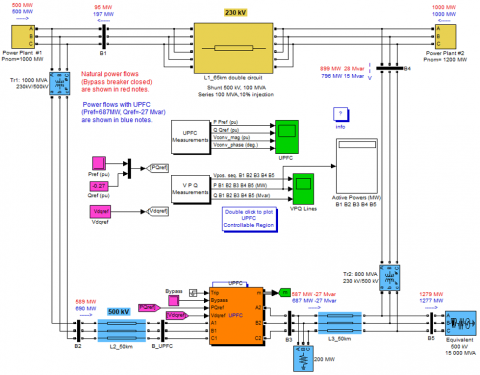
As shown in Figure 1, there is a toroidal configuration consisting of five buses (B1 to B5) and transmission lines (L1, L2 and L3), in addition to two transformers (Tr1 and Tr2). There are two power plants producing a total of 1,500 megawatts. Where, the energy is converted into the equivalent of 500 kilovolts and 15,000 megavolts A. There is a 200 MW load connected to bus B3. In normal operation, most of the power generated from Power Plant 2 is exported through three transformers between buses B4 and B5. When there is an emergency, only two transformers are available, as they reduce the power by 800 MVA. Load flow analysis reveals that most of the power generated from Power Station 2 is transmitted through the group of transformers with a capacity of 800 MW. Transformer Tr2 is overloaded by 99 MVA as the rest goes into the loop and the UPFC (unified power flow controller) controller at the right end of line L2 can help control the active and reactive powers on bus B3 and the voltage on bus B_UPFC. Which consists of two IGBT based inverters connected in shunt and series form with coupling reactors and transformers. The main purpose of using UPFC is to change the power flow which helps in relieving the power congestion in the system.
Figure 1. Control of power flow using a unified power flow controller (UPFC)
4.1 UPFC control strategies
4.1.1 Adjust and control of the corner of the phase [19]
- UPFC is able to control both voltage size and the phase angle simultaneously at its connection points.
- The SHUNT adapter works in parallel with the transport line, exchange interactive energy and maintain DC.
- The chain adapter injects the frequency current with a controlled size and the phase angle in a chain with the line.
- This UPFC capacity allows the regulation of active and interactive energy flows independently.
4.1.2 The congestion relief strategy
- To treat energy congestion, UPFC is published with a strategy that focuses on discovering lines that exceed its thermal borders through the current line measurements.
- By calculating the necessary corner correction (Δθ) using energy flow equations, UPFC aims to effectively reduce the extra load.
- Correct correction (Δθ) is injected into the line via the chain adapter to increase the transmission capacity without the need to build new lines.
- This process is repeatedly repeated using the closed loop control scheme in conjunction with the optimal energy flow algorithm to achieve the global optimal energy balance across the network.
4.1.3 Control and technology algorithm
- The UPFC chain adapter injects the variable voltage (VINJ) calculated using Eq. (3), where the VDC is the DC link, M is an amendment indicator, ωT is the frequency in the RAD/s, and θ is the corner of the phase in the leaders [20].
- The power flow control is achieved by changing the corner of the phase (θ), which changes the current line transmission according to the Eqs. (4) and (5), taking into account the typical values of 500 kV line.
- Many scenarios can be faced while UPFC, each requires a specific control strategy for optimal performance: Case 1: The excess line in one direction, the control strategy includes controlling the injection angle to reduce the flow in the excessive direction. Case 2: The excess line in both directions, the strategy aims to share the excess load equally by controlling the angles of injections in both directions. Case 3: The line in the thermal limit, but the interactive energy exceeded, the strategy focuses on regulating interactive energy by controlling the angles of injections. Case 4: A multi-loaded line, optimal power flow control is used across several UPFCs to reduce in-line overload. Case 5: Line-quick response output required to restore the power flow pattern after a tripping line by regulating the phase angle based on real-time measurements.
Through the use of these control strategies along with efficient algorithms and technologies, UPFC offers fast, flexible and stable control of multi-terminal HV transmission, demonstrating great technical and economic effectiveness in modern network congestion scenarios. The integration of advanced control algorithms and technologies enhances UPFC's ability to effectively handle congestion and ensure reliable power transmission in dynamic grid environments.
5.1 Assumptions in simulation
5.1.1 Perfect system representation
Simulation is likely to assume perfect representation of the power system, with simplified models of ingredients such as transformers, loads and transport lines. This abstraction may not fully pick up the complications and linear in the real world's energy networks.
5.1.2 Fixed state conditions
Simulation may assume the conditions of operating the stable condition to facilitate the analysis and accounts. This assumption may ignore transient or dynamic behaviors in the energy system that can affect UPFC in different scenarios.
5.1.3 Linear models
Simulations may use linear models for UPFC operating components and power system components. Although linear models provide analytical susceptibility, they may not pick up the full range of non -linear reactions and effects that can affect UPFC.
5.1.4 Fixed parameters
Parameters are supposed to be like voltage, current, corner values, active energy boundaries, interactive energy bodies are fixed or within pre -defined ranges. Detractions from these assumptions in the real-world scenarios can affect the effectiveness of UPFC control strategies.
5.2 The test system used
5.2.1 Test system
Topology. A planning representation of the test system that includes multiple buses (contract) is created with transportation lines.
Training. A simple network layout is designed with buses, transformers and transportation lines arranged in a ring or radi outlet to simulate the structure of the realistic energy network.
5.2.2 Line parameters
Transport lines. Transport lines are identified including resistance, induction, delivery, and capacity per unit of length.
Transformer parameters. Determining transformer properties such as classifications, the percentage of turns, losses, and disabilities.
5.2.3 Load profiles
Load modeling. Modeling different types of loads (e.g., resistance, inductive, and capacitance) connected in different buses in the system.
Load dynamics. Consider dynamic load profiles to simulate realistic differences and fluctuations in power consumption.
5.2.4 Simulation tools
Software. Simulation programs such as MATLAB/Simulink were used to model and analyze the behavior of the test system.
5.2.5 Validation and sensitivity analysis
Validation. Validation of the test system model against known standards or real-world data to verify its accuracy and reliability.
Sensitivity analysis. Sensitivity tests were performed by changing parameters (line lengths, load profiles, etc.) to evaluate the durability of UPFC control strategies.
5.3 Main results
5.3.1 UPFC control parameters
- P Pref (pu) set at 5.87 pu initially, increased to 6.87 pu for enhanced active power control.
- Q Qref (pu) maintained at -0.27 pu throughout, ensuring consistent reactive power management.
- Vconv_mag (pu) at 0.089 pu plays a crucial role in achieving the desired active power increase at bus B3.
- Vconv_phase (deg.) set at 30 degrees allows effective control over active power with a changing phase angle.
5.3.2 Line overload analysis
Active power limit analysis. Calculated through Gaussian distribution to determine the maximum active power handling capacity at different angles, Excess active power over 400 MW indicates line overload in one direction.
Overload in both directions. Condition identified through absolute values exceeding 400 MW for active power and 200 MVar for reactive power, Active power limits (P_limit and P_limit_negative) plotted to illustrate both direction overloads.
Reactive power limitation. Threshold of absolute reactive power exceeding 200 MVar highlights line near thermal limits with reactive power change issues, Reactive power limit (Q_limit) graphed using a Gaussian distribution to display the limitation.
5.3.3 System health implications
Line overload in both directions. Indicates critical congestion issues leading to excessive line loss, voltage drop, and potential system failures, Urgent actions required to ensure safe and reliable grid operation, including congestion management and grid modernization.
5.3.4 Operational considerations
Handling overloads. Swift response essential to prevent system instabilities and ensure grid reliability, Proactive measures like implementing congestion management techniques and enhancing energy infrastructure are necessary.
5.3.5 Simulation output
Active power and reactive power. Calculated values show active power at 43,301.27 MW and reactive power at 24,999.99 MVar, these results provide insights into the system's dynamic behavior and the critical role of effective power flow management.
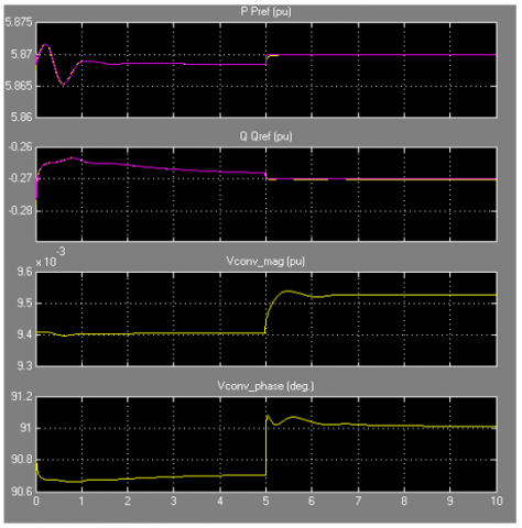
As in Figure 2, the following parameters play a crucial role in controlling the active and reactive powers on bus B3 through the operation of the UPFC which is responsible for determining the characteristics of the power flow and injecting the required voltage and thus allows for effective power flow control and congestion management in the power system.
• P Pref (pu): represents the reference active power parameter of the UPFC series converter, which for the specific scenario mentioned in the cases we have described is initially set at 5.87 pu (corresponding to a normal flux of 587 mW) at t = 10s, it is increased by 1 pu (100 mW) to a value of 6.87 pu.
• Q Qref (pu): This parameter represents the reference reactive power of the UPFC series converter. For the specific scenario mentioned in the cases we have described, it is initially set and kept constant at -0.27 pu throughout the simulation.
• Vconv_mag (pu): This parameter represents the magnitude of the series voltage injected by the UPFC series converter. Within the simulation process, the magnitude of the series voltage was set to 0.089 pu as it helps achieve the required increase in active power at bus B3.
• Vconv_phase (deg.): This parameter represents the phase angle of the series voltage injected by the UPFC series converter. For the cases mentioned at the beginning, it is set to 30 degrees, which allows the active power in bus B3 to increase, but the phase angle can also begin to change at a rate of 45 degrees per second but its effect will only be on P Pref (pu).
Figure 2. P Pref (pu), Q Qref (pu), Vconv_mag (pu) and Vconv_phase (deg.)
These parameters play a crucial role in controlling the active and reactive powers on bus B3 through the operation of the UPFC. It determines the characteristics of the power flow and the required voltage injection, allowing effective power flow control and congestion management in the power system.
We have also designed the same circuit to access line overloaded in both directions using Python where the system and line parameters defined at the beginning of the code need to be understood. These parameters include voltage, current and angle values and calculate the active power (P) and reactive power (Q) using the Eqs. (6) and (7).
$P~=~V1~\times ~I1~\times ~cos\left( theta1~-~theta2 \right)$ (6)
$Q~=~V1~\times ~I1~\times ~sin\left( theta1~-~theta2 \right)$ (7)
The line is overloaded in one direction: If the calculated P is greater than 400 the line will be overloaded in one direction.
We plotted the active power limit (P_limit) as a function of the angle (theta) using the Gaussian distribution and we displayed the diagram that shows the active power limit and the title “Excess line in one direction.”
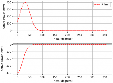
The line is overloaded in both directions: If the absolute value of the calculated P is greater than 400 and the absolute value of the Q is greater than 200 then the line is overloaded in both directions, P_limit and negative active power limit (P_limit_negative) as functions of angle (theta) using Gaussian distributions, show two subcharts: one for the active power limit and one for the passive active power limit, Add appropriate labels and titles and legends to subplots.
If the absolute value of the calculated P is less than or equal to 400 and the absolute value of Q is greater than 200 the line is within the thermal limit but the change in reactive power (ΔQ) has been exceeded and we have drawn the reactive power limit (Q_limit), as a function of angle (theta) using a Gaussian distribution and we have displayed the chart showing the reactive energy limit and the title “ΔQ exceeded within the thermal limit”, if there are multiple overloaded lines (selected in the lines list) loop over each line number and print a message indicating that the line is overloaded.
If line output print the calculated P and Q values, the results were as follows, P: 43301.270189221934 MW, Q: 24999.999999999996 MVar.
P_limit is calculated based on a Gaussian distribution. It represents the maximum active power that the line can handle at different angles (theta), the formula used to calculate the active power limit is: P_limit = 400 × exp (-(theta - theta1)2 / (2 × 202)), where theta1 is the angle of voltage V1.
Similarly, P_limit_negative is also calculated based on a Gaussian distribution, it represents the maximum active power in the opposite direction that the line can handle at different angles (theta), the formula used to calculate the negative active power limit is: P_limit_negative = -400 × exp (-(theta - theta2)2 / (2 × 202)), where theta2 is the angle of voltage V2.
Figure 3. Line overloaded in both directions
As shown in Figure 3, “Line overload in both directions” refers to a condition in a power system where a transmission line carries a current or power greater than its rated capacity in both forward and reverse directions of power flow which can lead to various problems such as excessive line loss, voltage drop. Hence, through this process and through the graphic line, we learn about the problem and know the risk of the line tripping or failing. When the transmission line is overloaded in both directions, it is evidence of high energy demand or congestion in the system. This can occur due to insufficient transmission infrastructure and due to factors, such as increased electricity consumption and limitations in power flow control mechanisms. Operators and control systems need to address this issue immediately to ensure safe and reliable operation of the power grid. Actions may include implementing congestion management techniques and recongestion. Distribution of energy flows, modernization of transmission lines, or improvement of energy generation and distribution.
5.4 UPFC performance analysis in different scenarios
5.4.1 UPFC performance analysis in different scenarios
Benefits. 1) UPFC enables precise control of active and reactive power flow, resulting in improved system performance. 2) Better grid stability and reduced voltage fluctuations improve the quality of electrical energy.
Limitations. 1) The limitation of UPFC capacity may lead to restrictions on the management of active power that are necessary. 2) Changes in network conditions which are quickly varying may be difficult for controlling parameter adjustments.
5.4.2 Congestion management
Benefits. 1) UPFC has the potential to enhance the efficiency of the grid by redistributing energy flows in transmission lines in the best way possible hence reducing energy congestion. 2) Utilize existing infrastructure better without having to undertake extensive modifications.
Limitations. 1) The process of coordinating UPFC activities among various substations is complex and may make it difficult to achieve smooth congestion relief. 2) UPFC does not work effectively in extremely jammed roads, which are outside its control capabilities.
5.4.3 Voltage regulation
Advantages. 1) Utilization of UPFC voltage control strategy to keep voltages constant within acceptable limits, thus averting their collapse. 2) Enhance network reliability and decreasing the chance of cascading outages.
Disadvantages. 1) The problem of receiving voltage regulations from more than one bus system may result in voltage disparities. 2) System stability can be interrupted by the regulation of voltages in times of extreme network conditions or load swings.
5.4.4 System efficiency and power transfer capacity
Benefits. 1) UPFC makes the power system work better by increasing how much power it can carry and by lessening losses during transmission. 2) It leads to better overall performance of the grid while also enabling more electricity to be transmitted.
Shortcomings. 1) The necessity for regular modifications of its control algorithms and setup parameters means depending on these measures when using UPFC will gain maximum benefit from the device. 2) Its performance effectiveness depends on such factors as the complexity of the system, network topology and other conditions influencing the energy transfer.
5.4.5 Integration with FACTS controllers and control strategies
Benefits. 1) By combining UPFC with POD and SSSC, it is possible to control power flow more effectively and mange congestion better. 2) Common control strategies increase transmission power utilization and improve network resilience.
Limitations. 1) The complexities of coordination in the implementation of multi-fact controllers may present operational challenges. 2) Interactions between different control strategies may lead to conflicting actions, affecting system stability and performance.
5.4.6 Real-time response and adaptability.
Benefits. 1) UPFC's rapid response capabilities allow dynamic adjustments to changing network conditions, ensuring system stability. 2) The ability to adapt to various operating conditions enhances network and reliability.
Limitations. 1) The delay in the decision -making process or the processing of the control signal may hinder the UPC performance in actual time, which affects its effectiveness in managing the cross -network events. 2) The sensitivity of external disorders and the anomalies may require controlling control parameters for optimal operation.
5.5 Comparative with the results of previous studies
The research presented in this study greatly contributes to the latest progress in the application of the uniform power flow control unit (UPFC) to manage energy congestion on the 500/230 kV network. By going into operational principles, control strategies, and UPFC's integration effects, this study provides a comprehensive analysis of its effectiveness in facing congestion challenges. Below is a comparison between how this research is presented to the latest previous studies.
5.5.1 A comprehensive evaluation via multiple parameters
Previous studies have focused on specific aspects such as promoting energy quality, UPFC application in energy systems, or historical analyzes. On the other hand, this research provides a more comprehensive assessment of UPFC effectiveness in reducing congestion by looking at active strength, interactive power, and voltage volume in a comprehensive way.
5.5.2 Simulation using advanced tools and techniques
While some previous studies have relied on the theoretical or limited simulation models, this research used advanced tools such as MATLAB/Simulink Sim power system for detailed simulation. By combining the real system components and network conditions, this study provides practical visions of UPFC in realistic network scenarios.
5.5.3 Explore the multi -UPFC control strategies
Unlike previous studies that primarily focused on individual control strategies, explore this research and compare different control methods, including the use of power fluctuation inhibitors (POD) and compensation for a fixed simultaneous chain (SSSC) to compensate for the voltage. This diverse analysis enhances UPFC ingenuity in congestion management.
5.5.4 Developing new control algorithms
By providing a new control algorithm, this research displays innovative strategies to enhance UPFC and the ability to adapt to the effectiveness of power congestion. Advanced control technologies improve operational efficiency and system reliability under different circumstances.
5.5.5 Focus on practical implementation and system integration
By implementing the devices on the test and evaluation seat in the integrated energy network, this study exceeds theoretical analyzes of verify UPC performance in the real-world scenarios. This research is of great importance as it shows how UPFC can be used effectively when there is congestion. It does this by focusing on how it is applied and how it is integrated into the system.
5.5.6 In-depth analysis of UPFC performance via different scenarios
The Ultra-Power Flow controllers (UPFC) operational scenarios and their control actions were discussed comprehensively. This analysis of various operational scenarios and UPFC responses to congestion proved to me a lot about how excess lines are regulated; and system voltage maintained at nominal levels regardless of any abnormal condition within the network, which would otherwise lead to managerial challenges. In order to better understand the congestion management we have simulated multiple cases and conducted a thorough analysis of output data to demonstrate UPFC operation under this concept.
The researcher drew on sophisticated simulation tools to assess UPFC performance with regard to congestion management, looked into a number of control strategies, developed unique control algorithms, and worked out various methods of employing these devices. In other words, this research makes a huge step forward in terms of improving the operations of the power grid and raising its performance standards, which will be used as a yardstick for future findings on improv.
The outcome and outcomes from the system in operation by employing unified power flow controller for solving congestion on 500/230 kV grid are somewhat practical in influence on operation and planning of powers systems. Below are a few practical impact that the results have
• Enhanced Network: Through its capability of effectively controlling power transmission and voltage the UPFC enhances the stability of the grid by reducing issues related to power impasse as well as voltages fluctuations. This contributes to maintaining reliable and stable energy supplies for consumers.
• Enhancing the quality of energy involves the regulation of active and reactive energy flows which help in enhancing energy transmission, reduction of transmission losses, and maintenance of good voltage levels which stabilize energy quality. This leads to a more dependable and efficient energy system.
• Results obtained indicate that UPFC leads to redistribution of electricity paths, reducing transportation lines’ overcrowding, hence improving current infrastructure utility without necessarily requiring huge promotions, hence enhancing the efficiency of transmitting energy and decreasing network congestions.
• Different operational scenarios are treated by various control strategies that are used by UPFC to the study. Considering advanced algorithms and real time adjustments, UPFC can swiftly react to changing network conditions hence maintaining an effective power flow control and also congestion management.
• When UPFC adaptation capacities are supported through quick response features, then a power system’s operating adaptability is increased, even in instances of dynamic instability and when it comes to management of energy transmission process in normal as well as emergency situations where lines stop randomly. The network’s elasticity and dependability are reinforced through operational flexibility.
• On congestion management, UPFC’s cost display effective in energy flow control improvement and voltage regulation without the necessity for extensive infrastructure upgrades. This can lead to cost savings for network operators while ensuring the operation of the effective network.
• Future planning and infrastructure development: The results of this study can inform the strategies for developing planning and infrastructure for energy systems. By demonstrating the effectiveness of UPFC in reducing congestion and enhancing network performance, network operators can consider implementing similar solutions to improve system reliability and efficiency.
UPFC was studied to administer congestion in an optimal manner on energy transmission systems through simulation and analytical analysis. The basic structure and operating principles of UPFC have been explained to provide visions about its unique ability to independent and consistent control of the active and interactive energy flow.
Various realistic scenarios were simulated to show UPFC's effectiveness when applying it individually and collectively in several sites to reduce lines loading and responding to line change events. The optimum energy flow algorithms are combined with high -range voltage transformers to achieve improved energy balance worldwide by controlling identification angles in all stations.
The results confirm that UPFC is completely suitable for regulating the real/reactive energy flow to redistribute the energy flow, maintaining stability under dynamic conditions and achieving a balance between loading and resources with safe energy transfer. Carvain control has a valuable academic base for dealing scientifically with the challenges of modern energy networks.
Compared to traditional methods, UPFC provides regulatory and enhanced trusted reliability and energy transmission capacity without expanding infrastructure, resulting in large technical and economic returns on investment for congestion management applications.
When clarifying the conceptual benefits, future studies can improve UPFC locations and control capabilities through multi -objective algorithms, taking into account practical regular restrictions, joint simulation platforms that combine electromagnetic models and improve UPFC control under broader privacy conditions, and finally experimental verification on actual distribution systems Vital visions of industrial applications will be presented towards updating the network structure.
In general, this study confirms the UPFC as a flexible current transmission technology that carries out optimal control plans to offer borders in the condes of the generation of the high input generation from the distributed energy sources.
Based on the restrictions and questions that were not answered in this study, future research can shed lights on possible research trends as follows:
- Improving UPFC locations: Future research can focus on improving UPFC locations using multi-targets to maximize trading and system efficiency in view of practical restrictions.
- Dynamic monitoring algorithms: UPFC's dynamic monitoring strategies can be searched to deal quickly with changing network conditions and enhance their real-time response ability to improve network performance.
- Share joining the platforms: A multi -power simulation that guarantees integration with electromagnetic transformations models with UPFC controls to improve their performance in light of the conditions with changing certainty, technically the experimental renewal provision that will provide vital visions of applied transport towards improving the network structure.
- Conditional tests: Conditioned tests can be done on actual distribution systems to assess UPFC's ability to expand and perform them in a broader range of network formations and operating scenarios.
- Combination with renewable energy sources: explore UPFC integration with renewable energy sources and variable generation technologies to improve energy flow control and increase network stability in modern energy systems.
By focusing on these possible research fields, future studies can enhance understanding and UPFC technology in operating and control of the power system, paving the way for more efficient, reliable and sustainable applications to better manage networks.
[1] Hingorani, N.G., Gyugyi, L. (2000). Understanding FACTS: Concepts and Technology of Flexible AC Transmission Systems. Wiley-IEEE Press.
[2] Edris, A. A. (1997). Proposed terms and definitions for flexible ac transmission system (FACTS). IEEE Transactions on Power Delivery, 12(4): 1848-1853. https://doi.org/10.1109/61.634216
[3] Acha, E., Agelidis, V.G., Anaya-Lara, O., Miller, T. (2002). Power Electronic Control in Electrical Systems. Newnes, Oxford.
[4] Ambriz-Pérez, H., Acha, E., Fuerte-Esquivel, C.R., Torre, A.D.L. (1998). Incorporation of a UPFC model in an optimal power flow using newtons method. IEE Proceedings - Generation, Transmission and Distribution, 145(3): 336-344. https://doi.org/10.1049/ip-gtd:19981944
[5] Pereira, M., Zanetta, L.C. (2013). A current based model for load flow studies with UPFC. IEEE Transactions on Power Systems, 28(2): 677-682. https://doi.org/10.1109/TPWRS.2012.2206409
[6] Robak, S., Rasolomampionona, D.D. (2009). Interactions analysis of UPFC multifunction controller. In 2009 IEEE Bucharest PowerTech, Bucharest, Romania, pp. 1-7. https://doi.org/10.1109/PTC.2009.5281943
[7] Zang, H.X., He, T.Y., Liu, J.K. (2016). Linear optimal power flow model with unified power flow controller in hot-start environment. Power System Technology, 40(11): 3517-3523. https://doi.org/10.1088/1755-1315/69/1/012152
[8] Sharafi, F. (2020). Enhancement and efficiency improvement the power systems by using unified power flow controller. In 4th International Conference on Applied Researches in Science and Engineering.
[9] Sawhney, H. (2002). Power system performance enhancement using unified power flow controller. MSc dissertation, Memorial University of Newfoundland, Newfoundland and Labrador, Canada.
[10] Anwer, N., Siddiqui, A.S., Umar, A. (2012). Analysis of UPFC, SSSC with and without pod in congestion management of transmission system. In 2012 IEEE 5th India International Conference on Power Electronics (IICPE), Delhi, India, pp. 1-6. https://doi.org/10.1109/IICPE.2012.6450489
[11] Parvathy, S., Thampatty, K.C.S., Nambiar, T.N.P. (2020). Design and implementation of partial feedback linearization controller for unified power flow controller. Electric Power Systems Research, 187: 106438. https://doi.org/10.1016/j.epsr.2020.106438
[12] Venegas, T., Fuerte-Esquivel, C.R. (2000). Steady-state modelling of thyristor controlled series compensator for phase domain load flow analysis of electric networks. In DRPT2000. In International Conference on Electric Utility Deregulation and Restructuring and Power Technologies. Proceedings (Cat. No.00EX382), London, UK, pp. 191-196. https://doi.org/10.1109/DRPT.2000.855662
[13] Hingorani, N.G. (1988). High power electronics and flexible AC transmission system. IEEE Power Engineering Review, 8(7): 3-4. https://doi.org/10.1109/MPER.1988.590799
[14] Noroozian, M., Andersson, G. (1993). Power flow control by use of controllable series components. IEEE Transactions on Power Delivery, 8(3): 1420-1429. https://doi.org/10.1109/61.252669
[15] Yu, Q., Cao, N., Guo, J. (2012). Analysis on influence of load rate on power system self-organized criticality. Dianli Xitong Zidonghua/Automation of Electric Power Systems, 36(1): 24-27, 37. https://doi.org/10.3969/j.issn.1000-1026.2012.01.005
[16] Bhowmick, S., Das, B., Kumar, N. (2008). An indirect UPFC model to enhance reusability of newton power-flow codes. IEEE Transactions on Power Delivery, 23(4): 2079-2088. https://doi.org/10.1109/TPWRD.2008.923105
[17] Masand, D., Jain, S., Agnihotri, G. (2008). Control strategies for distribution static compensator for power quality improvement. IETE Journal of Research, 54(6): 421-428. https://doi.org/10.4103/0377-2063.48632
[18] Jebaseelan, S.D.S., Prabu, R.R. (2012). Modelling and simulation of thirty bus system using multiple Statcom & TCTC. European Journal of Scientific Research, 81(2): 285-297.
[19] Pagola, F.L., Perez-Arriaga, I.J., Verghese, G.C. (1989). On sensitivities, residues and participations: Applications to oscillatory stability analysis and control. IEEE Transactions on Power Systems, 4(1): 278-285. https://doi.org/10.1109/59.32489
[20] Lei, X.Z., Lerch, E.N., Povh, D. (2001). Optimization and coordination of damping controls for improving system dynamic performance. In 2001 Power Engineering Society Summer Meeting. Conference Proceedings (Cat. No.01CH37262), Vancouver, BC, Canada. https://doi.org/10.1109/PESS.2001.970147