Henchiri Abdelhamid*![]() | Tahar Bahi
| Tahar Bahi![]()
© 2024 The authors. This article is published by IIETA and is licensed under the CC BY 4.0 license (http://creativecommons.org/licenses/by/4.0/).
OPEN ACCESS
In recent years, the adoption of photovoltaic technology has become increasingly attractive and popular due to the rising global demand for power. The energy conversion structure considered in this study, as well as its investigation, undoubtedly constitute the main tasks for the design and projection of photovoltaic systems connected to the electric distribution network. This paper presents the mathematical model of a photovoltaic system, along with the design of a maximum power point tracking algorithm and control. Subsequently, the dynamic performance of the photovoltaic generator connected to the distribution network via inverters is examined under various climatic conditions. Simulation results demonstrate that the controllers ensure optimal operation of the photovoltaic panel at its maximum power point, maintaining the DC output voltage at its reference level regardless of atmospheric conditions in terms of dynamic response time, overshoot, and reference tracking.
photovoltaic, buck-boost, DC control, MPPT, incremental conductance, grid system
Electric power generation is undergoing significant changes during this decade. This is mainly due to the demand of electricity which increase drastically, with the development of renewable which is unlimited, non-polluting and whose exploitation causes fewer damages on the environment [1]. The renewable energies harness natural resources abundantly available in our environment, such as sunlight, wind, water, and geothermal heat. These resources are essentially limitless but can be accessed without the same concerns about depletion as with finite fossil fuels [2]. Solar and wind power, for instance, benefit from declining costs of technology and installation, making them attractive options for both large-scale and distributed energy generation. Photovoltaic (PV) systems present a compelling solution as a renewable energy source (RES). Their utilization has been notably emphasized in grid-connected applications due to the numerous benefits associated with employing RES in distributed generation systems (DSG). Nowadays, using renewable energy resources as a power supplier in a power generating system instead of conventional ones has been more popular. Furthermore, a sensitivity analysis is also performed considering variations in two important parameters, namely solar irradiation (G) and temperature (T). These systems possessing significant advantages over traditional energy sources such as oil and natural gas. However, their efficiency and controllability remain notable drawbacks. Integrating photovoltaic (PV) systems with the utility grid, power electronic converters become essential components. This integration commonly involves the use of a voltage source inverter along with a boost converter. The dynamic nature of PV systems, influenced by factors like temperature, solar radiation, and load variation, leads to fluctuations in voltage, current, and power output. PV generators exhibit nonlinear current-voltage characteristics, complicating their control. Moreover, the optimal operating point of a PV array varies with changes in solar irradiation and cell temperature. Consequently, the online tracking of the maximum power point (MPPT) is crucial for optimizing the performance of PV systems. Efforts to address these challenges through research and technological advancements have been documented extensively in the studies [3-8]. To maximize power extraction from the PV generator, a sophisticated approach involves employing an optimal algorithm for Maximum Power Point Tracking (MPPT) in conjunction with loop control mechanisms utilizing a Proportional Integral (PI) controller. This controller adjusts the duty cycle to maintain the output voltage at the desired reference level, ensuring efficient operation of the DC bus [9-11]. Effective integration of renewable energy-based electricity production systems necessitates a thorough analysis of photovoltaic systems connected to the distribution network. This analysis enables accurate prediction of their dynamic performance under varying operating conditions. Such insights are crucial for making informed decisions regarding the feasibility of integrating this technology into the electric utility grid.
This work focuses on optimizing energy output through the implementation of MPPT techniques. Various methods, including hill climbing, perturb and observe, particle swarm optimization, fuzzy logic control, ant colony optimization, neural networks, cuckoo search, and others, have been employed [12-14]. These techniques aim to track the maximum power that the generated power can produce. In this study, we specifically utilize the Incremental Conductance method for MPPT, which is implemented on a DC-DC converter circuit. Furthermore, the key findings of numerical simulations conducted in this study are associated with achieving optimal performance under variable conditions, primarily solar irradiation and temperature fluctuations.
The use of the configuration structure of the photovoltaic chain connected to the electrical grid considered in this study is primarily motivated by its ability to harness a renewable, clean, and abundant energy source: the sun. This energy source offers inexhaustible potential and contributes to reducing greenhouse gas emissions, while providing greater energy independence. The associated control represents a significant advancement compared to existing energy production systems. It enables more precise and efficient management of electricity production by regulating solar energy fluctuations, thus optimizing the overall system efficiency. This technological innovation paves the way for a deeper integration of renewable energies into electrical grids, thereby contributing to a transition towards a more sustainable and resilient energy future. Indeed, these systems play a predominant role in meeting the increasing energy demands of our modern societies. By harnessing solar energy and converting it into electricity, they contribute to diversifying and securing the energy supply while reducing dependence on fossil fuels and limiting greenhouse gas emissions. Economically, their deployment promotes job creation in the renewable energy sector and stimulates technological innovation. Moreover, by enabling decentralized electricity production, photovoltaic systems offer a sustainable and adaptable solution to local energy needs while enhancing the resilience of electrical grids against disruptions.
The paper is structured as follows: Section 2 presents the configuration of the studied power conversion system. Section 3 delves into the modeling of PV array configurations and the underlying principles. Boost converter modeling and the MPPT algorithm based on incremental conductance are detailed in Sections 4 and 5, respectively. The performance evaluation of the grid-connected photovoltaic system is demonstrated through numerical simulations in Section 6. Finally, Section 7 provides a summary of the main conclusions.
The configuration of the electric power generation system under investigation in this study, aimed at analyzing the performance of a photovoltaic (PV) system connected to the grid, is depicted in Figure 1.
Figure 1. Bloc diagram of studied system
This system comprises several components: the photovoltaic generator (PVG), a two-level inverter (DC/AC converter) responsible for synchronizing sinusoidal current output with grid voltage and power, and a step-up DC-DC converter (boost converter) utilized for maximum power point tracking control. Throughout this study, three key aspects will be addressed: ensuring operation of the PV module at its maximum power point, regulating the output voltage of the boost converter, and injecting sinusoidal current into the grid. Detailed models of each component within the overall structure are provided in Figure 1.
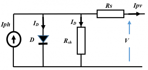
In this part, In this part, mathematical model of photovoltaic cell and the control principle of maximizing power output using the incremental conductance algorithm is elaborated upon, alongside the optimization of boost output voltage control. Photovoltaic energy production directly converts incident solar radiation into DC electric power. The photovoltaic cell, functioning as a semiconductor diode with a p-n junction, is pivotal in this process. The equivalent circuit of a photovoltaic cell, employing the single exponential model, is illustrated in Figure 2 [15-17].
Figure 2. Electrical circuit of PV cell
The equivalent circuit and fundamental equations of the PV cell under Standard Test Conditions (STC: Temperature = 25℃ and Irradiance level = 1000 W/m2) are provided. STC serves as a benchmark for measuring the nominal output power of PV cells. The equations governing the output current and voltage of the photovoltaic cell are as follows:
${{I}_{pv}}={{I}_{ph}}-{{I}_{D}}-{{I}_{sh}}$ (1)
where, Iph represents photovoltaic current.
This current is heavily influenced by the ambient and standard levels of solar radiation (Go and Gs = 1000 W/m2) as well as the ambient and standard temperature of the solar cell (To and Ts = 25℃ = 298 K), as described in the following equation [18-20]:
${{I}_{ph}}=\left[ {{I}_{sc}}+K\left( {{T}_{o}}-298 \right) \right]\frac{{{G}_{o}}}{1000}$ (2)
where, Isc represents the short-circuit current of the cell under Ts on which the saturation current (Io) depends, expressed by the following relationship:
${{I}_{o}}={{I}_{rs}}{{(\frac{{{T}_{o}}}{{{T}_{s}}})}^{3}}{{e}^{[\frac{q.{{E}_{go}}({1{T}_{s}}-1/T)}{nK}]}}$ (3)
with,
${{I}_{rs}}=\frac{{{I}_{sc}}}{{{e}^{(\frac{q{{V}_{oc}}}{n{{N}_{s}}KTo})}}-1}$ (4)
while ID is characterized using the Shockley equation for an ideal diode.
${{I}_{D}}={{I}_{Ds}}\left( \exp \frac{{{V}_{pv}}-{{R}_{s}}}{{{V}_{T}}}-1 \right)$ (5)
where, VT is the thermal voltage, which depends on the diode ideality factor (n), the Boltzmann constant (K = 1.38 × 10⁻²³ J/K), and the elementary charge (q = 1.6 × 10⁻¹⁹ C), as demonstrated in the following expression:
${{V}_{T}}=\frac{n.K.{{T}_{o}}}{q}$ (6)
Thus, considering the equivalent electrical circuit of the cell shown in Figure 2, we deduce the shunt current (Ish) flowing through the shunt resistance (Rsh):
${{I}_{sh}}=\frac{{{V}_{pv}}+{{R}_{s}}{{I}_{pv}}}{{{R}_{sh}}}$ (7)
In constructing a photovoltaic panel, cells are arranged in series and parallel configurations. Connecting cells in series enhances the output voltage, while parallel connections increase the output current. The mathematical model representing the power produced by the photovoltaic panel simplifies into a basic algebraic model defined by the current-voltage relation:
${{I}_{pv}}={{I}_{ph}}-Io\left[ e(\frac{q({{V}_{pv}}+{{R}_{s}}{{I}_{pv}}}{nKN{{T}_{o}}} \right]-{{I}_{sh}}$ (8)
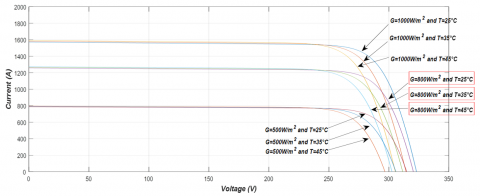
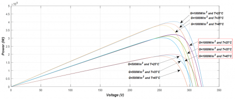
The parameters IPh, IRS, RS, Rsh are essential for determining the characteristics: Ipv=f(Vpv) and Ppv=f(Vpv), under various operating conditions. Additionally, these parameters are influenced by the incident solar radiation and the cell temperature. In practical terms, each PV module is characterized by its reference values under Standard Test Conditions (STC), which include a solar radiation (G) of 1000 W/m², a solar cell temperature (T) of 25℃, and an air mass (AM) of 1.5.
The equations previously discussed have allowed the development of programming for each subsystem of the photovoltaic module. Taking into account the installation specifications, such as the required load, the characteristics of the electrical grid, as well as the atmospheric conditions to consider for performance analysis under different situations, the choice fell on the SunPower SPR-315E-WHT-D photovoltaic module, whose parameters are presented in Table 1. The parameters of the photovoltaic Module: SunPower SPR-315E-WHT-D, used in this work are shown in Table 1. Figure 3 and Figure 4 show, respectively, the I = f(V) and P = f(V) characteristics on weather condition of the solar irradiation: (1000 W/m2, 800 W/m2 and 500 W/m2) and temperature ( 25℃, 35℃ and 45℃). In this work there is the use of four (4) identical modules.
Table 1. Electrical specification of PV module
|
Module: SunPower SPR-315E-WHT-D |
|
Parallel strings 64 |
|
Series-connected modules per string 5 |
|
Maximum power Pm=315,072W |
|
Open circuit voltage Voc=64,6V |
|
Voltage et maximum power point Vmp=54,7V |
|
Temperature coefficient -0,27269%/deg.C |
|
Celle per module Ncel=96 |
|
Short-circuit current Isc=6.14A |
|
Current at maximum power point Imp=5.76A |
|
Temperature coefficient Isc=0.061694 |
Moreover, the analysis of the forms of the maximum output powers obtained under different climatic conditions is depicted in Table 2.
Table 2. Maximal powers
|
|
P=1000 W/m2 |
P=800 W/m2 |
P=600 W/m2 |
|
T=25℃ |
4.0330e+05 |
3.2254e+05 |
2.0036e+05 |
|
T=35℃ |
3.9114e+05 |
3.1272e+05 |
1.9409e+05 |
|
T=45℃ |
3.7881e+05 |
3.0276e+05 |
1.8773e+05 |
As the second main component of the studied chain, we will delve into the structure, operation, and modeling of the boost converter in detail in the following section.
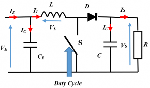
The Boost converter is deployed to raise the voltage of the photovoltaic array to a level essential for the inverter's optimal performance. Regulated by the duty ratio (α), it enables the average output quantities to be expressed in proportion to the input. The equivalent circuit is illustrated in Figure 5.
Figure 5. Equivalent circuit of DC/DC converter
During the initial cycle (αT), the switch (S) is closed, allowing the current through the inductance (L) to gradually increase as it stores energy. Subsequently, when S opens, the inductance (L) opposes the decrease in current, generating a voltage that is added to the source voltage. This combined voltage is then applied to the load (R) through the diode (D). Kirchhoff's laws are applied to analyze the two equivalent electric circuit cases of the chopper.
During the first switching phase α.Ts, the switch S is closed:
${{I}_{{{C}_{1}}}}={{C}_{1}}+\frac{d{{V}_{g}}}{dt}={{I}_{g}}-{{I}_{L}}$ (9)
${{I}_{C2}}={{C}_{2}}+\frac{d{{V}_{0}}}{dt}=-{{I}_{0}}$ (10)
${{V}_{L}}=L\frac{d{{I}_{L}}}{dt}={{V}_{g}}-{{R}_{L}}{{I}_{L}}$ (11)
Kirchhoff's laws are applied to the two electric circuits of the chopper.
During the first switching phase, S is open:
${{I}_{{{C}_{1}}}}={{C}_{1}}+\frac{d{{V}_{g}}}{dt}={{I}_{g}}-{{I}_{L}}$ (12)
${{I}_{C2}}={{C}_{2}}\frac{d{{V}_{0}}}{dt}={{I}_{L}}-{{I}_{0}}$ (13)
${{V}_{L}}=L\frac{d{{I}_{L}}}{dt}={{V}_{g}}-{{V}_{0}}-{{R}_{L}}{{I}_{L}}$ (14)
These two configurations are mainly determined by the duty cycle signal used to control the semiconductor. Indeed, this signal corresponds to the MPPT control output, which will be described in detail in the following section.
Boost converters serve to efficiently transfer maximum power from the solar array to the DC bus, maintaining a coordinated approach and consistently delivering a voltage exceeding the input magnitude. The photovoltaic array is precisely charged at the Maximum Power Point (MPP), achieved through the implementation of a MPP Tracking algorithm [21, 22]. To optimize power extraction from the PV generator, the incremental conductance (INC) control method for MPPT is employed, particularly suited for variable temperature and insulation conditions.
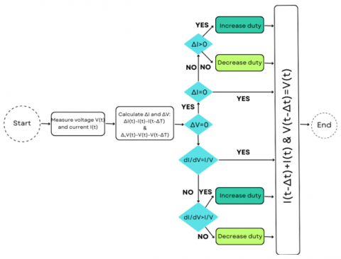
The use of the incremental Maximum Power Point Tracking (MPPT) technique offers several significant advantages over other methods. This approach enables dynamic and continuous optimization of the operating point of solar panels, maximizing their energy efficiency even under varying sunlight conditions. Additionally, incremental MPPT is relatively straightforward to implement and does not require expensive sensors, making it particularly appealing in practical applications. Its ability to quickly adapt to changes in environmental conditions makes it an efficient and cost-effective solution for photovoltaic systems, thereby contributing to optimal utilization of solar energy.
Figure 6. Flowchart of INC method
The voltage and current output of the photovoltaic network are subject to fluctuations due to unstable climatic conditions. To ensure the PV module operates at its maximum power point, the incremental conductance algorithm is utilized, leveraging observations from the P-V characteristic curve. By analyzing the derivative of the PV module, power reaches zero at the MPP, with positive values to the left and negative values to the right of the MPP. The MPP position can be determined using the relationship between dI/dv and –I/V; if dp/dv is negative, the MPPT lies to the right of the current position, and if positive, it lies to the left. The equations for the IC method are as follows:
$\frac{dp}{dv}=\frac{d(v.I)}{dv}=I\frac{dV}{dv}+v\frac{dI}{dv}$ (15)
MPP is reached when dp/dv=0:
$\frac{dp}{dv}>0\text{ then }{{V}_{P}}<{{V}_{mpp}}$ (16)
$\frac{dp}{dv}=0\text{ then }{{V}_{p}}={{V}_{mpp}}$ (17)
$\frac{dp}{dv}<0\text{ then }{{V}_{p}}>{{V}_{mpp}}$ (18)
The flowchart depicting the incremental conductance algorithm is illustrated in Figure 6.
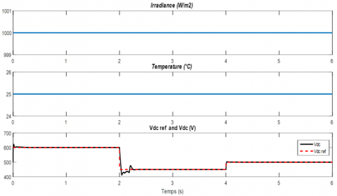
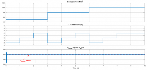
In this section, two main simulation tests were conducted to assess the performance of the system under consideration. Initially, the system operates under standard conditions (G = 1000 W/m2 and T = 25 ℃), with the output voltage reference of the Boost converter varying. Figure 7 illustrates the solar radiation, temperature, and Vdcconditions imposed for this initial test. It's noteworthy that the output voltage of the Boost converter accurately follows the reference value, while the voltage and current (Vg and Ig) of the network remain synchronized. Indeed, under these initial conditions where irradiance and temperature are maintained at their standard values, by abruptly changing the reference voltage (Vdcref) from 600 V to 450 V and then to 500 V, as illustrated in the figure, we observe that the actual voltage promptly follows its initial setpoint, with a slight overshoot of approximately 3%. This phenomenon also occurs when decreasing the reference voltage. Thus, in terms of speed (response time and overshoot), the response to the setpoint exhibits good performance. Additionally, the currents and voltages are sinusoidal and perfectly synchronized, indicating a low level of harmonics and excellent energy flow quality. The reactive power remains zero, resulting in a unitary power factor.
(a)
(b)
(c)
Figure 7. Characteristics: G and T, and Vref variable. (a) G and T standards and Vdc reference, (b) Zoom: voltage and current grid, (c) Active and reactive powers
Figure 8. Solar radiation, temperature and Vdc,ref
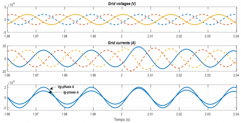
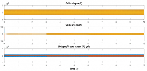
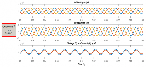
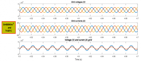
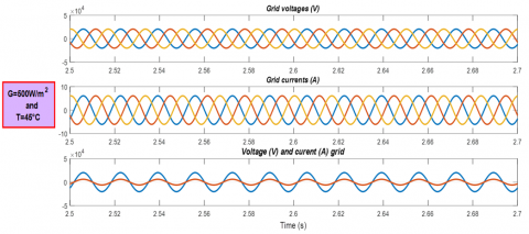
The second test, it is conducted under conditions where irradiance and temperature fluctuate, while the Vdcreference remains constant, as depicted in Figure 8. The corresponding simulation results are presented in Figure 9, where in three distinct zones are zoomed in: (G = 1000 W/m2, T = 25℃ - Standard conditions); (G = 800 W/m2, T = 35℃); and (G = 500W/m2, T = 45℃). These graphical representations demonstrate that the system's behavior aligns precisely with the imposed conditions, ensuring synchronization throughout. Despite the challenging conditions imposed, the system exhibits robust performance in this scenario as well.
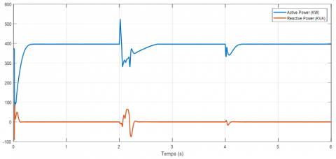
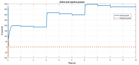
Figure 10 shows the evolutions of the active and reactive powers obtained under the imposed conditions (see Figure 8). The active power (solid line) follows correctly the imposed evolution and also, the reactive power (discontinuous line) is forced to zero thanks to the command. Furthermore, it is worth noting that the transition from one power level to another occurs rapidly and almost without any significant overshoot. Additionally, the power levels obtained correspond perfectly to those of the maximum powers discussed in the graphs of the current and power characteristics as a function of the photovoltaic generator voltage.
(a)
(b)
(c)
(d)
Figure 9.Grid voltages and grid currents. (a) Grid voltage and current , (b) Zoom: standard conditions, (c) G = 800W/m2 and T = 35°C, (d) G = 500W/m2 and T = 45°C
Figure 10. Active and reactive powers
This paper addresses the critical aspects of electric energy production systems reliant on renewable sources, specifically focusing on the regulation of DC voltage through a Proportional-Integral (PI) controller, as well as the utilization of the incremental conductance algorithm for Maximum Power Point Tracking (MPPT) and control in a grid-connected photovoltaic system. The comprehensive content of the paper presents a detailed mathematical model encompassing a three-phase grid-connected photovoltaic generator, incorporating both the photovoltaic array and the electronic power conditioning system.
Through extensive simulation studies conducted under standard operating conditions and various other potential scenarios, the results demonstrate the promising performance of the grid-connected photovoltaic system. These findings underscore the efficacy of the proposed methodologies in enhancing the efficiency and reliability of renewable energy-based electricity production systems. Furthermore, the robustness exhibited by the system across diverse operating conditions suggests its viability for real-world applications, thereby contributing positively towards the advancement and adoption of sustainable energy solutions. It is worth emphasizing the practical importance of photovoltaic systems connected to the electrical grid, both in terms of meeting energy needs and addressing economic and environmental challenges. By effectively addressing energy, economic, and environmental imperatives, grid-connected photovoltaic systems play a crucial role in the transition towards a more sustainable and balanced society.
|
Ipv |
Photovoltaic current of PV cell [A] |
|
IDS |
Reverse saturation current of PV cell [A] |
|
Rs |
Equivalent series resistance of the PV [Ω] |
|
Rsh |
Equivalent parallel resistance of the PV [Ω] |
|
q |
Electron charge [C] |
|
k |
Boltzmann constant [J/K] |
|
Ns |
Number of cells connected in series |
|
Nsh |
Number of cells connected in parallel |
|
Voc |
Open-circuit voltage of the PV module [V] |
|
Isc |
Short-circuit current of the PV module [A] |
|
ID |
Diode current [A] |
|
A |
Solar cell diode P-N junction ideality factor; |
|
D |
Diode |
|
Ish |
Shunt resistor current [A] |
|
n |
Diode ideality factor |
|
VT |
Thermal voltage [V] |
|
Ipv |
Photovoltaic current of PV cell [A] |
|
STC |
Standard test conditions |
[1] Parida, B., Iniyan, S., Goic, R. (2011). A review of solar photovoltaic technologies. Renewable and Sustainable Energy Reviews, 15(3): 1625-1636. https://doi.org/10.1016/j.rser.2010.11.032
[2] Benmouiza, K. (2022). Comparison analysis of different grid-connected PV systems topologies. Journal European des Systemes Automatises, 55(6): 779-785. https://doi.org/10.18280/jesa.550610
[3] Chaabane, M., Charfi, W., Mhiri, H., Bournot, P. (2019). Performance evaluation of solar photovoltaic systems. International Journal of Green Energy, 16(14): 1295-1303. https://doi.org/10.1080/15435075.2019.1671405
[4] Kumar, A.S., Reddy, V.U. (2021). Performance evaluation of PV panel configurations considering PSC's for PV standalone applications. Journal Européen des Systèmes Automatisés, 54(6): 847-852. https://doi.org/10.18280/jesa.540606
[5] Rathore, N., Panwar, N.L., Yettou, F., Gama, A. (2021). A comprehensive review of different types of solar photovoltaic cells and their applications. International Journal of Ambient Energy, 42(10): 1200-1217. https://doi.org/10.1080/01430750.2019.1592774
[6] Ali Khan, M.Y., Liu, H., Yang, Z., Yuan, X. (2020). A comprehensive review on grid connected photovoltaic inverters, their modulation techniques, and control strategies. Energies, 13(16): 4185. https://doi.org/10.3390/en13164185
[7] Sahu, H.S., Nayak, S.K. (2016). Extraction of maximum power from a PV array under nonuniform irradiation conditions. IEEE Transactions on Electron Devices, 63(12): 4825-4831. https://doi.org/10.1109/ted.2016.2616580
[8] Lakhdara, A., Bahi, T., Moussaoui, A., (2020). PSO control under partial shading conditions. Algerian Journal of Renewable Energy and Sustainable Development, 2(2): 126-136. https://doi.org/10.46657/ajresd.2020.2.2.5
[9] Gada, S., Fekik, A., Mahdal, M., Vaidyanathan, S., Maidi, A., Bouhedda, A. (2023). Improving power quality in grid-connected photovoltaic systems: A comparative analysis of model predictive control in three-level and two-level inverters. Sensors, 23(18): 7901. https://doi.org/10.3390/s23187901
[10] Al-Dhaifallah, M., Nassef, A.M., Rezk, H., Nisar, K.S. (2018). Optimal parameter design of fractional order control based INC-MPPT for PV system. Solar Energy, 159: 650-664. https://doi.org/10.1016/j.solener.2017.11.040
[11] Rakesh, R., Kannan, S.A., Jomy, J., Kamala, D.V., Jayaraju, M. (2014). Modelling and analysis of MPPT techniques for grid connected PV systems. International Journal of Engineering Research & Technology, 2(2): 1031-1037.
[12] Karami, N., Moubayed, N., Outbib, R. (2017). General review and classification of different MPPT Techniques. Renewable and Sustainable Energy Reviews, 68: 1-18. https://doi.org/10.1016/j.rser.2016.09.132
[13] Henchiri, A., Bahi, T., Khochemane, L., Lekhchine, S. (2018). Control of the DC voltage output photovoltaic system. Proceedings of Engineering and Technology–PET, 38: 69-74.
[14] Abed, I.A., Ali, M.M., Abed, A.A. (2022). Study comparison between enhanced firefly and differential evolution to solve the maximum power point tracking problem. Journal Européen des Systèmes Automatisés, 55(5): 641-647. https://doi.org/10.18280/jesa.550509
[15] Rasool, F., Drieberg, M., Badruddin, N., Singh, B.S.M. (2017). PV panel modeling with improved parameter extraction technique. Solar Energy, 153: 519-530. https://doi.org/10.1016/j.solener.2017.05.078
[16] Olujimi, A., Aaron, I., Adebayo, O., Afolarin, A., Jonathan, E. (2022). Smart solar powered irrigation system. Journal Européen des Systèmes Automatisés, 65(4): 535-540. https://doi.org/10.18280/jesa.550413
[17] Pendem, S.R., Mikkili, S. (2018). Modeling, simulation, and performance analysis of PV array configurations (Series, Series-Parallel, Bridge-Linked, and Honey-Comb) to harvest maximum power under various Partial Shading Conditions. International Journal of green Energy, 15(13): 795-812. https://doi.org/10.1080/15435075.2018.1529577
[18] Rasheed, M.S., Shihab, S. (2020). Modelling and parameter extraction of PV cell using single-diode model. Advanced Energy Conversion Materials, 1(2): 96-104. https://doi.org/10.37256/aecm.122020550
[19] Henchiri, A., Bahi, T., Khochemane, L. (2017). Performances of solar photovoltaic under different climatic conditions. CIMSI, November.
[20] Kadeval, H.N., Patel, V.K. (2021). Mathematical modelling for solar cell, panel and array for photovoltaic system. Journal of Applied and Natural Science, 13(3): 937-943. https://doi.org/10.31018/jans.v13i3.2529
[21] Roshan, R., Yadav, Y., Umashankar, S., Vijayakumar, D., Kothari, D.P. (2013). Modeling and simulation of Incremental conductance MPPT algorithm based solar photo voltaic system using CUK converter. In 2013 International Conference on Energy Efficient Technologies for Sustainability, Nagercoil, India, pp. 584-589. https://doi.org/10.1109/ICEETS.2013.6533450
[22] Dahmani, A., Himour, K., Guettaf, Y. (2023). Optimization of power quality in grid connected photovoltaic systems. Journal Européen des Systèmes Automatisés, 56(6): 1095-1103. https://doi.org/10.18280/jesa.560619