Jingfang Zhang
© 2024 The author. This article is published by IIETA and is licensed under the CC BY 4.0 license (http://creativecommons.org/licenses/by/4.0/).
OPEN ACCESS
As research on parallel mechanisms with limited degrees of freedom (DOF) continues to grow, this paper introduces a novel 2UPU-2SPU parallel mechanism that features 2 Rotational and 2 Translational (2R2T) motion capabilities. The SPU branches are symmetrically positioned relative to the plane of the 2UPU branches, endowing the mechanism with a full-circle DOF that encompasses two rotations and two translations. One of the rotational DOF influences the characteristics of a constrained rotational freedom. This study conducts a kinematic analysis using screw theory to elucidate the DOF and derives the inverse kinematics of the mechanism. Furthermore, by employing motion/force transmission performance indicators and performance maps, the mechanical performance characteristics are analyzed. A mathematical model for optimizing mechanical performance using the Particle Swarm Optimization (PSO) algorithm is established, facilitating the design of specific mechanical devices. The mechanism boasts a large workspace, with the operational space varying as the moving platform rotates, making it suitable for applications requiring minimal rotational and lateral movements but significant longitudinal displacement.
parallel mechanism, 2R2T, kinematics, optimization, workspace
The existence of parallel mechanisms has a long history, but it is fair to say that research on the kinematics of parallel mechanisms only gradually began in the 1960s. In 1962, Gough and Whitehall [1] invented a 6-DOF tire testing device using a system of jacks connected by joints; Stewart [2] first conducted a kinematic study of this mechanism in 1965, and also built a simulated flight environment for aircraft flight training based on this mechanism model, making it the most widely used parallel mechanism to date.
Compared to 6-DOF parallel mechanisms, parallel mechanisms with fewer DOF cannot perform some complex motions, but they have advantages such as simple structure, low cost, fewer drive components, easy control, and large workspace. Rolland [3] proposed two types of 4-DOF parallel mechanisms for material handling: Manta & Kanuk. Tsai and Joshi [4] analyzed and studied the 3-UPU parallel mechanism through research on the structural characteristics of parallel manipulators. Chen et al. [5] proposed a 4-DOF parallel platform manipulator with 2 Rotational Prismatic Spherical (PRS) and 2 Prismatic Spherical Spherical (PSS) support chains, and conducted a kinematic analysis of this 2T2R parallel mechanism. Li and Huang [6] used the method of constraint synthesis for a systematic type synthesis of 4-DOF parallel robots, and proposed a 2R2T parallel mechanism with 2 symmetrical support chains. Yoon and Ryu [7] proposed two types of 4-DOF spatial parallel mechanisms with two platforms: 1T3R and 2T2R. These are relatively early studies on parallel mechanisms with fewer DOF.
As parallel mechanisms are widely applied in various fields, scholars have paid more attention to parallel mechanisms with fewer DOF. Research on parallel mechanisms such as 3R, 3T, 2R1T, 3T2R, 2T1R, and 2R2T has increased.
Xie et al. [8] considered force transmission and analyzed the kinematic optimization design of 2-DOF parallel mechanisms using a 4R parallel mechanism as an example; combining configuration evolution with Lie group theory, Fan et al. [9] proposed a type synthesis method applied to 2T2R, 1T2R, and 2R parallel mechanisms. Ye et al. [10] used the motion equivalent chain method to obtain a type synthesis of a class of 2R2T parallel mechanisms, and Araujo-Gómez et al. [11] designed a 3UPS-1RPU parallel manipulator with 2R2T DOF. Nurahmi et al. [12] studied the constraint-based design, optimization design, and reconstruction strategy of the 3-RPS parallel robotic arm. Chai et al. [13] proposed system dynamics modeling and analysis of a 2PRU-UPR parallel robot based on the screw theory.
By 2022, research on parallel mechanisms with fewer DOF has increased significantly. Zhang et al. [14] proposed a 3-DOF parallel mechanism based on an antenna support structure. Yan et al. [15] introduced a novel 5-DOF redundantly actuated 4PUS-PPPU parallel mechanism with a large tilting ability, including its design, analysis, and control. Song et al. [16] performed dynamic modeling and generalized force analysis of the 3-RPS parallel mechanism based on five-dimensional geometric algebra space, and Zhou et al. [17] proposed a new 5-DOF weakly coupled compliant parallel mechanism. Ye et al. [18] proposed a type synthesis of a 4-DOF non-overconstrained parallel mechanism with a symmetrical structure. Qin et al. [19] analyzed the workspace of the 3-RPS parallel mechanism based on the significant characteristics of the rotational branching mechanism. Song et al. [20] analyzed symmetric 3-UPU parallel mechanisms and their variant mechanisms under different geometric and assembly conditions. Shi et al. ;21] proposed a novel bionic 5-DOF parallel actuation mechanism by establishing a mapping relationship between local musculoskeletal systems of organisms and mechanism configurations, and Pan et al. [22] proposed and studied a new 3R parallel compliant mechanism.
In the aforementioned research on parallel mechanisms with fewer DOF, due to the variety of 2R2T parallel mechanisms, the literature related to the kinematic analysis and research of 2R2T parallel mechanisms is relatively limited. Analyzing and studying new types of 2R2T parallel mechanisms has significant practical engineering application implications. Therefore, this paper proposes a 2UPU-2SPU parallel mechanism, conducts a solution for the inverse kinematics of this mechanism, and analyzes the workspace. The analysis results show that this mechanism has great potential in fields like machine tools, agriculture, aerospace, and medical, where there is not a high demand for motion dimensions but a high requirement for mechanical performance.
2.1 DOF analysis under initial assembly configuration
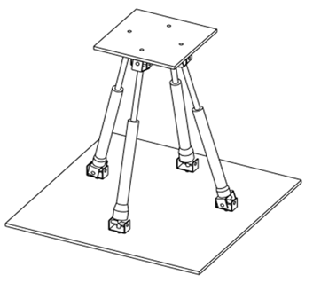
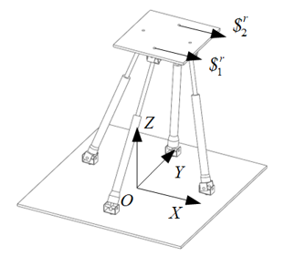
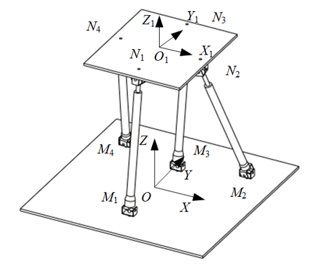
As shown in Figure 1, the 2UPU-2SPU parallel mechanism consists of two rectangular platforms, two UPU branches, and two SPU branches. The UPU branch includes two universal joints (U-joints) and one prismatic joint (P-joint) between them. The SPU branch consists of a spherical joint (S-joint), a P-joint, and a U-joint. A U-joint is composed of two rotational joints that intersect perpendicularly, while an S-joint is made up of three rotational joints intersecting perpendicularly.
Figure 1. Initial assembly configuration of the 2UPU-2SPU mechanism
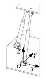
First, the UPU branch is analyzed, and a branch coordinate system is established as shown in Figure 2. The origin is at the intersection of the rotating axis of the U-joint connected to the fixed platform. The direction of X1 axis is perpendicular to the axis line of the first rotational joint in the U-joint, the direction of Y1 axis follows the direction of the first rotational joint's axis line, and the direction of Z1 axis is perpendicular to the fixed platform plane.
Figure 2. The UPU branch coordinate system
Through analysis, the motion screws of the joints on the branch are obtained as:
$\left\{\begin{array}{l}\boldsymbol{S}_1=\left(\begin{array}{llllll}1 & 0 & 0 ; & 0 & 0 & 0\end{array}\right) \\ \boldsymbol{S}_2=\left(\begin{array}{llllll}0 & m_2 & n_0 ; & 0 & 0 & 0\end{array}\right) \\ \boldsymbol{S}_3=\left(\begin{array}{llllll}0 & 0 & 0 ; & 0 & b_3 & c_3\end{array}\right) \\ \boldsymbol{S}_4=\left(\begin{array}{llllll}0 & m_4 & n_4 ; & a_4 & 0 & 0\end{array}\right) \\ \boldsymbol{S}_5=\left(\begin{array}{lllllll}1 & 0 & 0 ; & 0 & b_5 & c_5\end{array}\right)\end{array}\right.$ (1)
By calculating the reciprocal screws of this screw system, we get:
$\boldsymbol{\$}^r=\left(\begin{array}{llllll}1 & 0 & 0 ; & 0 & b & c\end{array}\right)$ (2)
The reciprocal screw of this branch is parallel to the X-axis and passes through the intersection of the two rotating axes of the U-joints fixed to the moving platform. Since the two UPU branches are fixed in the same manner, they generate parallel, co-directional constraint forces on the moving platform.
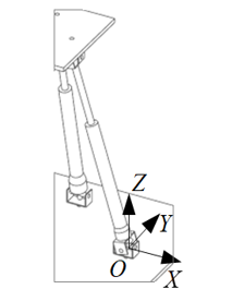
Next, the SPU branch is analyzed, and a branch coordinate system is established as shown in Figure 3, with the origin at the intersection of the rotating axis of the U-joint connected to the fixed platform.
Figure 3. The SPU branch coordinate system
Through analysis, the motion screws of the joints on the branch are obtained as:
$\left\{\begin{array}{l}\boldsymbol{S}_1=\left(\begin{array}{llllll}1 & 0 & 0 ; & 0 & 0 & 0\end{array}\right) \\ \boldsymbol{S}_2=\left(\begin{array}{llllll}0 & m_2 & n_2 ; & 0 & 0 & 0\end{array}\right) \\ \boldsymbol{S}_3=\left(\begin{array}{llllll}0 & m_3 & n_3 ; & 0 & 0 & 0\end{array}\right) \\ \boldsymbol{S}_4=\left(\begin{array}{llllll}0 & 0 & 0 ; & 0 & b_3 & c_3\end{array}\right) \\ \boldsymbol{S}_5=\left(\begin{array}{lllllll}0 & m_4 & n_4 ; & a_4 & 0 & 0\end{array}\right)\\ \boldsymbol{S}_6=\left(\begin{array}{lllllll}1 & 0 & 0 ; & 0 & b_5 & c_5\end{array}\right)\end{array}\right.$ (3)
The reciprocal screws of this screw system are found to be:
$\boldsymbol{\$}^r=\left(\begin{array}{llllll}0 & 0 & 0 ; & 0 & 0 & 0\end{array}\right)$ (4)
The constraint screw of this branch is zero, indicating an unconstrained branch, used only for realizing the motion drive of the mechanism.
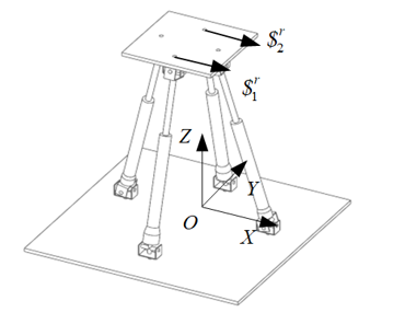
From the analysis above, it is evident that the moving platform of the 2UPU-2SPU parallel mechanism has two constraint screws along the X-axis that are co-directional and parallel, as shown in Figure 4.
Figure 4. Constraint screws on the moving platform
These two constraints can be equivalently considered as a constraint force along the X-axis and a constraint couple around the Z-axis on the plane, limiting the moving platform's DOF for movement along the X-axis and rotation around the Z-axis. The mechanism retains the DOF for movement along the Y-axis, Z-axis, and rotation around the X-axis and the Y-axis.
The analysis above describes the DOF under the mechanism's initial configuration. Below, we demonstrate that the DOF of two rotations and two translations are full-circle DOF, meaning that the nature of the DOF does not change with the movement of the mechanism.
2.2 Full-circle DOF analysis for parallel mechanisms
Under the initial configuration, the 2UPU-2SPU mechanism cannot move along the X-axis. However, when the moving platform moves within the YOZ plane, the direction and relative position of the constraints from the two UPU branches do not change, remaining parallel and along the X-axis, as shown in Figure 5. Therefore, when the moving platform undergoes movement, the DOF does not change, still preventing movement along the X-axis and rotation around the Z-axis.
Figure 5. Constraint screws after movement
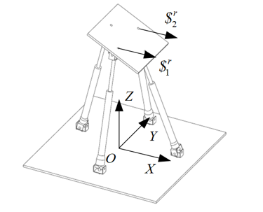
When the P-joint of the SPU branch undergoes unequal displacements, the moving platform rotates around the Y-axis. Using screw theory to analyze the constraints of the two branches under this configuration, the distribution of constraint forces is shown in Figure 6, where the nature of the DOF remains consistent with that during movement of the moving platform only.
Figure 6. Rotation around the Y-axis
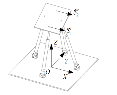
When the P-joint of the UPU branch undergoes unequal displacements, the moving platform rotates around the X-axis. Using screw theory to analyze the constraints of the two branches under this configuration, the attained distribution of constraint forces is shown in Figure 7. The direction of the two constraints remains parallel to the X-axis, but their relative position changes from being parallel to the fixed platform plane to being parallel to the moving platform plane, restricting movement along the X-axis and rotation around the normal to the moving platform.
Figure 7. Rotation around the X-axis
In summary, after the moving platform of the mechanism undergoes finite motion, its constraint properties do not change, and the nature of its DOF remains unchanged. Therefore, the mechanism possesses two rotations and two translations as full-circle DOF.
To obtain the coordinates of the motion pair connected to the motion platform in the fixed coordinate system, use a transformation matrix to convert the coordinates from the moving coordinate system to the fixed coordinate system. Assuming the rotation angles around the X, Y and Z axes are $\alpha, \beta$ and $\gamma$. respectively, the transformation matrix is:
$\begin{gathered}{ }_o^{o_1} \boldsymbol{R}=\boldsymbol{R}_x \boldsymbol{R}_y \boldsymbol{R}_z= {\left[\begin{array}{ccc}1 & 0 & 0 \\ 0 & c \alpha & -s \alpha \\ 0 & s \alpha & c \alpha\end{array}\right]\left[\begin{array}{ccc}c \beta & 0 & s \beta \\ 0 & 1 & 0 \\ -s \beta & 0 & c \beta\end{array}\right]\left[\begin{array}{ccc}c \gamma & -s \gamma & 0 \\ s \gamma & c \gamma & 0 \\ 0 & 0 & 1\end{array}\right]}\end{gathered}$ (5)
where, c represents cos, s represents sin. Due to the restriction of rotation around the Z-axis in the 2UPU-2SPU parallel mechanism (lack of freedom to rotate around the Z-axis), so $\gamma$ = 0.
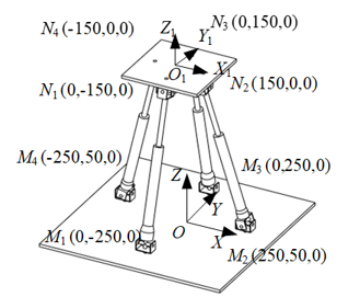
To perform inverse kinematic analysis based on the 2UPU2SPU parallel mechanism with 2R2T DOF, let's assume the moving platform's rotation angle $\alpha^{\circ}$ around the $\mathrm{X}$-axis, the rotation angle $\beta^{\circ}$ around the $\mathrm{Y}$-axis, and its center coordinates in the base coordinate system, are known. By calculating the coordinates of the U-joint on the moving platform in the base coordinate system, we can determine the distance between the two ends of each branch. Let $M_i$ represent the center of the Ujoint or S-joint on the fixed platform, $N_i$ represent the center of the U-joint on the moving platform, $O$ represent the center of the fixed platform, and $O_1$ represent the center of the moving platform. The length of the branch can be represented as $\left|M_i N_i\right|$ :
$\boldsymbol{M}_i \boldsymbol{N}_i=-\boldsymbol{O} \boldsymbol{M}_i+\boldsymbol{O} \boldsymbol{O}_1+\boldsymbol{O}_1 \boldsymbol{N}_i$ (6)
Given $M_i O$ and $O O_1$, we only need to calculate the vector representation of $O_1 N_i$ in the base coordinate system. Using the rotation matrix formula for rotation about a fixed axis, we get:
${ }_{o_1}^o \boldsymbol{R}=\boldsymbol{R}_x \boldsymbol{R}_y=\left[\begin{array}{ccc}c \beta & 0 & s \beta \\ 0 & c \alpha & -s \alpha \cdot c \beta \\ 0 & s \alpha & c \alpha \cdot c \beta\end{array}\right]$ (7)
Finally, we can get $O N_i$:
$\boldsymbol{O} \boldsymbol{N}_i={ }_{o_1}^O \boldsymbol{R} \boldsymbol{N}_i+\boldsymbol{O} \boldsymbol{O}_1=\left[\begin{array}{lll}x_i & y_i & z_i\end{array}\right]^{\mathrm{T}}$ (8)
Let $O M_i$ be $\left[\begin{array}{lll}X_i & Y_i & Z_i\end{array}\right]^T$, then the length $\left|M_i N_i\right|$ of the $\mathrm{P}-$ joint is:
$L_i=\sqrt{\left(x_i-X_i\right)^2+\left(y_i-Y_i\right)^2+\left(z_i-Z_i\right)^2}$ (9)
In summary, the inverse kinematics solution for the 2UPU-2SPU parallel mechanism is completed.
Compared with serial mechanisms, parallel mechanisms excel in force transmission. Evaluating the mechanical performance of a mechanism is a crucial step in using parallel mechanisms for the design of specific devices. Additionally, conducting a mechanical evaluation can also help to avoid the mechanism's singular points. In research on mechanical performance evaluation, some commonly used performance indices by scholars are the motion/force transmission performance indicators.
The motion/force transmission performance indices for parallel mechanisms include the input transmission performance index and the output transmission performance index, which assess the efficiency of motion/force transmission within the branches and between the branches and the moving platform, respectively. These indices can be calculated using screw theory. The input transmission index $\lambda_{I i}$ for branch $i$ of a parallel mechanism is given by:
$\lambda_{I i}=\frac{\left|\$_{I i} \circ \$_{I i}\right|}{\left|\$_{T i} \circ \$_{I i}\right|_{\max }}$ (10)
where $\$_{I i}$ is the unit input motion screw for branch i, i.e., the motion screw of the actuated movement in the branch; $\$_{T i}$ is the driving force screw for branch i, which has a reciprocal product of zero with other non-driven motion screws within the branch.
Analyzing the UPU and SPU branches of the device, and choosing the P-joint as the actuator, its input motion screw $\$_{I i}$ can be represented as:
$\$_{I i}=(0 ; v)=\left(\begin{array}{llllll}0 & 0 & 0 ; & 0 & p_i & q_i\end{array}\right)$ (11)
The reciprocal product of the driving force screw $\$_{T i}$ with the motion screws of the $\mathrm{U}$ or $\mathrm{S}$ joints is zero, meaning $\$_{T i}$ is parallel or intersects with these motion screws, thus having the same direction as the P-joint. Ultimately, by calculating Eq. (9), $\lambda_{I i}$ is always 1.
Next, we analyze the device's output transmission performance index. The output transmission performance index $\lambda_{O i}$ for branch i is represented as:
$\lambda_{O i}=\frac{\left|\$_{T i} \circ \$_{O i}\right|}{\left|\$_{T i} \circ \$_{O i}\right|_{\max }}$ (12)
where $\$_{O i}$ represents the unit output motion screw of the moving platform, which is the instantaneous motion screw of the moving platform when only driven by this branch $i$, with all other branches locked. In this case, $\$_{O i}$ does not perform work with the force constraining the moving platform $\$_{W c i}$ and the driving force of other branches $\$_{T j}$, so it is calculated as:
$\left\{\begin{array}{l}\boldsymbol{\$}_{I j} \circ \boldsymbol{\$}_{O i}=0 \quad(j=1,2,3,4 \quad j \neq i) \\ \boldsymbol{\$}_{W c j} \circ \boldsymbol{\$}_{O i}=0 \quad(j=1,3 \quad i=1,2,3,4)\end{array}\right.$ (13)
By calculation, the range of $\lambda_{O i}$ is $[0,1]$. Since the input transmission performance index is always 1 and cannot evaluate the performance of the mechanism, the output transmission performance index is used as the evaluation index. Ultimately, the motion/force transmission performance indicator for the mechanism is defined as the minimum of the output transmission performance indices of the four branches:
$\lambda_O=\min \left(\lambda_{O 1}, \lambda_{O 2}, \lambda_{O 3}, \lambda_{O 4}\right)$ (14)
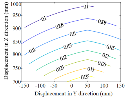
Setting the motion pairs of the fixed branches along the X-axis and Y-axis and symmetric about the origin, the motion/force transmission performance map of the mechanism is illustrated as shown in Figure 8. Since the 2UPU-2SPU mechanism has four DOF, for ease of representation, given values of $\alpha$ and $\beta$ are used to draw the performance map.
(a) Schematic diagram of joint arrangement
(b) $\alpha=0^{\circ}, \beta=0^{\circ}$
(c) $\alpha=20^{\circ}, \beta=10^{\circ}$
Figure 8. Transmission performance map
The analysis of the images leads to the following observations:
(1) Under this installation configuration, the mechanical performance of the mechanism in various poses is not high;
(2) The mechanical performance decreases as the height of the moving platform increases;
(3) When the moving platform undergoes deflection, there is a slight improvement in the mechanical performance of the mechanism.
Further analysis is conducted on the reason for phenomenon (1). The new constraint motion generated by locking other drives overlaps with its corresponding $M_i N_i$, primarily restricting the movement of the moving platform along the normal to the fixed platform. Since the angle between the driving force direction and the normal direction is small, most of the driving power is lost, resulting in poor mechanical performance of the mechanism in this pose. To improve the output transmission performance of the mechanism, the distance between $M_i$ and $N_i$ within the X-Y plane should be increased.
Given that the output force transmission index calculates the power coefficient between the driving force and the instantaneous movement of the moving platform, and the instantaneous movement of the moving platform can only be determined through calculation, an evaluation function is set to assess the output transmission performance of the mechanism in various poses, and PSO is utilized for optimization.
The formula for the flight velocity of each particle in a particle swarm is given by:
$\begin{aligned} v_i^{\prime}= & v_i+c_1 \times \operatorname{rand}() \times\left(\text { pbest }_i-x_i\right) +c_2 \times \operatorname{rand}() \times\left(\text { gbest }_i-x_i\right)\end{aligned}$ (15)
where, $v_i$ is the velocity of the $i$-th particle, to introduce randomness into the velocity calculation, use $\operatorname{rand}()$ generated uniformly between (0, 1), $x_i$ represents the current position of the particle, $c_1$ and $c_2$ represent the cognitive and social learning factors, respectively, pbest $_i$ represents the best position found by the particle during its flight process, and gbest $_i$ represents the best position found by any particle during the flight process of all particles.
The fitness calculation formula for the i-th particle can be expressed as:
$f_i=\frac{\iiint \tau d y d z d \alpha}{\iiint d y d z d \alpha}$ (16)
Then the evaluation function is defined as:
$f_i=\frac{\iiint \lambda_0 d y d z d \alpha}{2 \iiint d y d z d \alpha}+\frac{1-\sum_j^8\left(\left|X_{\text {limit }}^j / 2-X^j\right| / 8 X_{\text {limit }}^j\right)}{6}$ (17)
where, $y$ and $z$ are the displacements of the moving platform along the $\mathrm{Y}$ and $\mathrm{Z}$ axes, respectively; $\alpha$ is the rotation angle around the $\mathrm{X}$ axis; $\lambda_O$ is the minimum output transmission performance index of the mechanism in this pose; $X_{\text {limit }}^j$ represents the extreme values for the optimization object, and $X^j$ represents the current values of the optimization parameters. The second term of this polynomial function is used to assess the extent to which the installation positions of the joints are distant from the extreme positions, aiming to reduce the difficulty in the design of specific devices.
Table 1. Optimization parameters
|
Joint |
Parameter Representation |
|
M1 |
[0 -Y1 0] |
|
M2 |
[X2 -Y1 0] |
|
M3 |
[0 -Y3 0] |
|
M4 |
[-X4 Y4 0] |
|
N1 |
[0 -y1 0] |
|
N2 |
[x2 y2 0] |
|
N3 |
[0 y3 0] |
|
N4 |
[-x4 y4 0] |
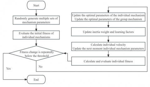
From the analysis in Chapter 3, it is known that the coordinates of $M_i$ and $N_i$ should be solved as parameters for the PSO. Here, $M_2$ and $M_4$ are symmetrical about the YOZ plane, with the same $\mathrm{Y}$-axis coordinates and opposite $\mathrm{X}$-axis coordinates. Similarly, $N_2$ and $N_4$ are symmetrical about the $\mathrm{Y}_1 \mathrm{O}_1 \mathrm{Z}_1$ plane, with their $\mathrm{Y}$-axis and $\mathrm{X}$-axis coordinates following the same symmetry as $M_2$ and $M_4$. Ultimately, optimization is performed on eight parameters of the motion joints, with specific position parameters as shown in Table 1. Analyzing the principles of the PSO, an optimization program for the 2UPU-2SPU parallel mechanism was developed, and a flow chart of its running process is given in Figure 9, with the program stopping when the fitness variation is less than $10^4$ more than 20 times.
Figure 9. Flowchart of the PSO
The number of individuals is set to 30 , with 100 iterations, and the restrictions on the P-joint's displacement length $L$, the rotation angle range Theta for axes not parallel to the P-joint, and the range of the joint installation coordinate parameters $X_i$, $Y_i, x_i, y_i$ are:
$\left\{\begin{array}{l}750 \mathrm{~mm} \leq L \leq 1100 \mathrm{~mm} \\ \mid \text { Theta } \mid \leq 60^{\circ} \\ 0 \mathrm{~mm}<X_i, Y_i<300 \mathrm{~mm} \\ 0 \mathrm{~mm}<x_i, y_i<200 \mathrm{~mm}\end{array}\right.$ (18)
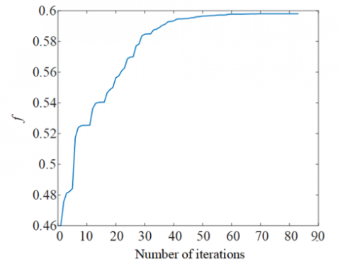
The relationship between the final convergence curve fitness and the number of iterations is shown in Figure 10. Analyzing the fitness value, the number of times the optimization fell into local optima was 5, achieving satisfactory optimization results.
Figure 10. Optimization convergence curve
Analyzing the parameters of the optimized individuals, rounding the results, and fine-tuning to determine the installation positions of the joints, as shown in Table 2.
The installation of the joints and the overall structure after optimization is shown in Figure 11.
Table 2. Final joint installation positions
|
Joint |
Coordinates (mm) |
|
M1 |
[0, -250, 0] |
|
M2 |
[265, 225, 0] |
|
M3 |
[0, 150, 0] |
|
M4 |
[-265, 225, 0] |
|
N1 |
[0, -150, 0] |
|
N2 |
[175, 30, 0] |
|
N3 |
[0, 250, 0] |
|
N4 |
[-175, 30, 0] |
Figure 11. Joint arrangement after optimization
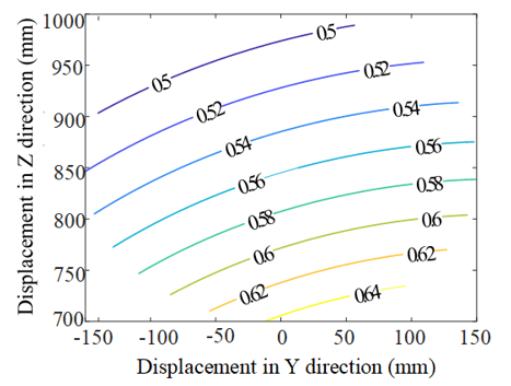
(a) Before optimization
(b) After optimization
Figure 12. Comparison before and after optimization
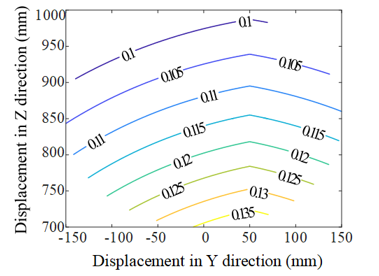
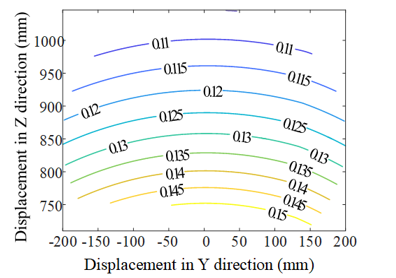
Before optimization, the fitness of the installation points shown in Figure 8(a) was 0.2316. After optimization, the fitness improved to 0.598. Comparing the performance maps as shown in Figure 12, there was a significant increase in the minimum motion/force transmission performance after optimization.
The images and calculation results reveal the following points:
(1) The output transmission performance of the mechanism has significantly improved after optimization;
(2) At the same Z-axis height, the output transmission performance decreases with an increase in displacement along the Y-axis;
(3) At the same Y-axis position, the output transmission performance decreases as the height on the Z-axis increases.
These results indicate that the mechanism is more suitable for operating within the second quadrant of the Y-Z coordinate system and that the working height needs to be carefully considered.
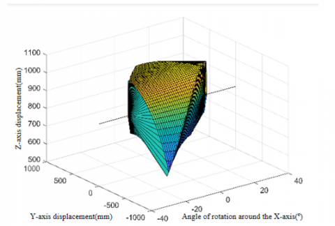
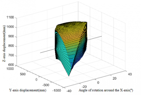
The 2UPU-2SPU parallel mechanism, having four DOF, requires a restriction on the rotation angle $\beta$ around the $\mathrm{Y}$-axis for a simplified description of the workspace in the threedimensional Cartesian coordinate system. The X-axis describes the rotation angle $\alpha$ of the moving platform around the $\mathrm{X}$-axis, while the $\mathrm{Y}$ and $\mathrm{Z}$ axes describe the displacements of the moving platform along the $\mathrm{Y}$ and $\mathrm{Z}$ axes, respectively.
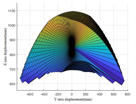
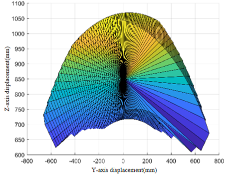
To facilitate the search for extreme positions, polar coordinates are used to assign values to $\mathrm{y}$ and $\mathrm{z}, y=$ $\phi \cos (\varphi), z=\phi \sin (\varphi)$, with the range of $\varphi$ being 0 to 30 and the range of $\phi$ being 0 to $360^{\circ}$, the angle between each branch and the normal to the fixed and moving platforms is restricted to 0 to $45^{\circ}$. Using Matlab programming, the workspace with the rotation angle set to $0^{\circ}$ and $10^{\circ}$ is shown in Figure 13.
(a) β=0° 3D view
(b) β=0° Y-Z view
(c) β=10° 3D view
(d) β=10° Y-Z view
Figure 13. Workspace
The images reveal the following observations:
(1) The effect of rotating the moving platform around the Y-axis within the range of 0 to 10° on the workspace is minimal;
(2) As the rotation of the moving platform around the X-axis increases, the workspace gradually shifts from the third quadrant of the X-Y plane to the first quadrant, transitioning from an inability to move in the positive range of the Y-axis to an inability to move in the negative range of the Y-axis.
The reason for the phenomenon (2) is further analyzed. At extreme angles, the two UPU branches reach their maximum and minimum limits, requiring shorter P-joint and longer length of the movement in one direction along the Y-axis. In contrast, movement in the opposite direction allows for increased and decreased displacement of the P-joint while maintaining the angle, leading to the occurrence of phenomenon (2).
(1) This paper introduces and analyzes the 2UPU-2SPU parallel mechanism. The two SPU branches are symmetrically installed relative to the plane containing the two UPU branches. The moving platform is subjected to parallel and co-directional constraint forces from the UPU branches, limiting one rotational and one translational DOF of the moving platform. The restricted direction of X-axis movement does not change, but the axis of the restricted rotational DOF changes with different modes of rotation of the moving platform.
(2) The kinematic inverse solution of the mechanism has been analyzed, yielding analytical expressions; the motion/force transmission performance indices were used to analyze the mechanical performance of the mechanism, with the output transmission performance index selected as the evaluation indicator. A PSO algorithm was designed for optimizing and evaluating the mechanical performance, utilizing performance maps to analyze changes in mechanical performance characteristics, identifying optimal working conditions.
(3) The workspace of the mechanism was analyzed, showing a large workspace when the rotation range of the moving platform is small, meeting general application requirements. However, as the rotation increases, the movement range in the positive or negative domain of the Y-axis decreases, while it increases in the opposite domain, indicating that the mechanism is suitable for applications requiring minimal rotation, minimal lateral displacement, and significant longitudinal displacement.
[1] Gough, V.E., Whitehall, S.G. (1962). Universal Tire Test Machine. International Congress of F.I.S.I.T.A., 117(9), 117-135.
[2] Stewert, D. (1966). A platform with 6 degrees of freedom. In Proc. IMech E, 180: 371-386.
[3] Rolland, L.H. (1999). The manta and the kanuk: Novel 4-DOF parallel mechanisms for industrial handling. Dynamic Systems and Control, 16349: 831-844. https://doi.org/10.1115/IMECE1999-0114
[4] Tsai, L.W., Joshi, S. (2000). Kinematics and optimization of a spatial 3-UPU parallel manipulator. Journal Mechanical Design, 122(4): 439-446. https://doi.org/10.1115/1.1311612
[5] Chen, W.J., Zhao, M.Y., Zhou, J.P., Qin, Y.F. (2002). A 2T-2R, 4-DoF parallel manipulator. In International Design Engineering Technical Conferences and Computers and Information in Engineering Conference, Montreal, Quebec, Canada, pp. 881-885. https://doi.org/10.1115/DETC2002/MECH-34303
[6] Li, Q., Huang, Z. (2003). Type synthesis of 4-DOF parallel manipulators. In 2003 IEEE International Conference on Robotics and Automation (Cat. No.03CH37422), Taipei, Taiwan, pp. 755-760. https://doi.org/10.1109/ROBOT.2003.1241684
[7] Yoon, J., Ryu, J. (2005). A new family of hybrid 4-DOF parallel mechanisms with two platforms and its application to a footpad device. Journal of Robotic Systems, 22(5): 287-298. https://doi.org/10.1002/rob.20065
[8] Xie, F., Liu, X., Wang, L., Wang, J. (2009). Optimum kinematic design of the 4R 2-DOF parallel mechanism. Tsinghua Science and Technology, 14(5): 663-668. https://doi.org/10.1016/S1007-0214(09)70132-4
[9] Fan, C., Liu, H., Zhang, Y. (2013). Type synthesis of 2T2R, 1T2R and 2R parallel mechanisms. Mechanism and Machine Theory, 61: 184-190. https://doi.org/10.1016/j.mechmachtheory.2012.10.006
[10] Ye, W., Fang, Y., Guo, S., Qu, H. (2014). Type synthesis of 2R2T parallel mechanisms based on motion equivalent chain method. Proceedings of the Institution of Mechanical Engineers, Part C: Journal of Mechanical Engineering Science, 228(17): 3209-3217. https://doi.org/10.1177/0954406214527271
[11] Araujo-Gómez, P., Díaz-Rodríguez, M., Mata, V., González-Estrada, O.A. (2019). Kinematic analysis and dimensional optimization of a 2R2T parallel manipulator. Journal of the Brazilian Society of Mechanical Sciences and Engineering, 41(10): 425. https://doi.org/10.1007/s40430-019-1934-1
[12] Nurahmi, L., Caro, S., Solichin, M. (2019). A novel ankle rehabilitation device based on a reconfigurable 3-RPS parallel manipulator. Mechanism and Machine Theory, 134: 135-150. https://doi.org/10.1016/j.mechmachtheory.2018.12.017
[13] Chai, X., Wang, M., Xu, L., Ye, W. (2020). Dynamic modeling and analysis of a 2PRU-UPR parallel robot based on screw theory. IEEE Access, 8: 78868-78878. https://doi.org/10.1109/ACCESS.2020.2989783
[14] Zhang, G., Xia, X., Hou, Y., Guo, J., He, J., Li, C. (2022). Optimal design and trajectory tracking experiment of a novel 3-DOF parallel antenna mechanism. AIP Advances, 12(2): 025321. https://doi.org/10.1063/5.0079915
[15] Yan, P., Huang, H., Li, B., Zhou, D. (2022). A 5-DOF redundantly actuated parallel mechanism for large tilting five-face machining. Mechanism and Machine Theory, 172: 104785. https://doi.org/10.1016/j.mechmachtheory.2022.104785
[16] Song, Z., Jiang, S., Chen, B., Wang, L., Wu, H. (2022). Analysis of dynamic modeling and solution of 3-RPS parallel mechanism based on conformal geometric algebra. Meccanica, 57(6), 1443-1455. https://doi.org/10.1007/s11012-022-01472-1
[17] Zhou, Y., Sun, J., Zhang, F., Li, S. (2022). Synthesis method of new weakly-coupled 5-DOF compliant parallel mechanism. Journal of Mechanical Science and Technology, 36(8): 3863-3873. https://doi.org/10.1007/s12206-022-0709-2
[18] Ye, W., Li, Q., Chai, X. (2022). Type synthesis of 4-DOF non-overconstrained parallel mechanisms with symmetrical structures. Machines, 10(12): 1123. https://doi.org/10.3390/machines10121123
[19] Qin, J., Yu, C., Sun, Z., Cao, L. (2022). A novel method for type synthesis of parallel mechanism without parasitic motion based on 2R1T parallel mechanism with rotational bifurcation. Chinese Journal of Mechanical Engineering, 35(1): 78. https://doi.org/10.1186/s10033-022-00747-8
[20] Song, J., Zhao, C., Zhao, K., Yan, W., Chen, Z. (2023). Singularity analysis and dimensional synthesis of a 2R1T 3-UPU parallel mechanism based on performance Atlas. Journal of Mechanisms and Robotics, 15(1): 011001. https://doi.org/10.1115/1.4053826
[21] Shi, H., Zhang, J., Wang, T., Li, R., Huang, Q. (2023). Mechanism design and kinematic analysis of a bioinspired 5-DOF parallel driving mechanism. Mechanism and Machine Theory, 181: 105178. https://doi.org/10.1016/j.mechmachtheory.2022.105178
[22] Pan, L., Zhang, J. W., Zhang, D., Tang, H. (2023). Modeling and analysis of a novel 3R parallel compliant mechanism. Machines, 11(3): 375. https://doi.org/10.3390/machines11030375