Ahmed M. Almawla*![]() | Marwan J. Hussein
| Marwan J. Hussein![]() | Afrah T. Abdullah
| Afrah T. Abdullah![]()
© 2024 The authors. This article is published by IIETA and is licensed under the CC BY 4.0 license (http://creativecommons.org/licenses/by/4.0/).
OPEN ACCESS
An overview of intelligent control techniques for the speed control of a direct current (DC) motor has been described in this study. Using the MATLAB SIMULINK platform, the individually excited DC motor speed control system implemented as a physical model. A mathematical model for both the sliding mode control (SMC) method and PID control, a traditional control methodology that ensures the speed controller has been developed. For comparison's sake, fuzzy logic is constructed using the Mamdani Technique with two inputs to obtain the necessary speed control. In addition, to select the optimal gain, the output signal of The PID controller and SMC were contrasted with fuzzy logic in terms of overshoot peak and stability time period. The outcomes prove the SMC's superiority over the PI controller and fuzzy logic approach. Based on time domain characteristics, this article presents a comparative study between Proportional-Integral-Derivative (PID), a sliding mode control (SMC), and fuzzy logic controller (FLC) controllers. The study concludes the less overshoot peak and fast response through fixed Properties for the DC motor and its mechanical variations due to operating conditions. Based on transient response study, the results show that SMC is superior to fuzzy logic and classical controllers PID.
PID controller, fuzzy logic controller, FLC, sliding mode control, SMC, DC motor speed control, MATLAB SIMULINK
Commercially, DC motors are used for speed control for industrial and residential purposes. There were two methods used for speed control mainly armature voltage control and field flux control. The involvement of Field flux for assessing the performance of the DC motor is more than the base speed and armature voltage is kept constant in this process [1, 2].
With PID control, the parameters can be changed to get a system that performs noticeably well, with minimal overshoot and good speed stability at the target value. In addition, the PID controller offers a quick system response with straightforward mathematical formulas. Conversely, non-linearity in the plant results in a decrease in PID performance [3].
Sliding mode control is an effective solution to handle complex, nonlinear, and high-order dynamic plants operating under uncertain conditions It is also considered as a high-speed switching feedback control that is reliable and efficient in managing both linear and non-linear DC Motor speed. SMCs are widely used in industrial environments [3].
It was proposed that fuzzy logic controllers be used to control the speed of a DC motor by varying the field current in the constant power region and the armature voltage in the constant torque region, thereby combining armature voltage and field current [4]. Fuzzy logic control applies the human way of thinking to control something, specifically in the form of "if-then" rules, rather than using traditional methods to obtain a control result using mathematical equations [5]. Thus, it makes sense that fuzzy logic control is used in the industrial sector to control DC motors [6].
In this research, three types of controllers were proposed to control the speed of a DC motor. A Fuzzy Logic, PID, and SMC controller by using MATLAB, and Simulink, were intended to achieve increased control precision, decreased settling time, and improved steady-state performance. Reliable accuracy is provided by the fuzzy controller for DC motors.
It provides a wide range of speed control and requires manual or automatic control. So, often designers try to find the best control method that can help in controlling the motor output (position or speed) to a predefined set point [7].
1.1 Literature review
Previous studies provided several types of controllers for enhancing the DC motor's performance. PID controllers are the most widely used controllers in industrial control processes because of their robust performance under a variety of operating conditions, easy design, as well as simple structure. The first PID was developed in 1911 by Elmer Sperry for the US Navy, but Minorsky introduced in 1922 the PID control method that we use today [8]. Several modifications were made to it in the 1930s and these have been in industrial use of various process control works ever since the 1940s [9].
PID controller performance is mainly determined by how accurately system models and their parameters are developed. It is essential to obtain a fine-tuning of parameters to achieve the desired control action. As manual tuning can prove to be a tedious task so, numerous efforts were made for tuning the PID. Ziegler and Nichols gave the well-known Ziegler-Nichols tuning method in 1942-1943 [10, 11]. Father Cohen and Coon gave the alternative for tuning in the 1950s which was accepted by certain types of plants [12].
Several other tuning methods and strategies like fractional order PID [13], DSP-based self-tuning IP [14], etc. We're introduced to improve the performance of PIDs, some of which are discussed in the studies [14, 15]. However, PIDs are often inefficient for a system with undefined complexities like time delays, oscillatory behavior, nonlinearities, or for multiple-input multiple-output (MIMO) systems [16]. Additionally, a kick or spike called a set-point kick is experienced in the output due to the proportional and derivative action of the PID whenever there is a change in the set point [17]. This action can cause serious damage to the system receiving the control signal from the controller like a motor, control valve, etc. These effects are avoided by modifying the PID controller structure to the I-PD controller [18].
Recently, intelligent process control has drawn the attention of many. Fuzzy logic control (FLC) gives an intelligent tuning that uses a linguistic control algorithm based on rules that use general statements instead of mathematical equations [19]. It has been suggested as a better control than the conventional control algorithms in complicated systems with dynamics that are not certain and those with nonlinearities [20].
Lotfi A. Zadeh introduced fuzzy logic, a fuzzy set-based logic, in 1965. According to Mamdani and Assilian, fuzzy logic was successfully applied for the first-time control. Furthermore, Kingt and Mamdani proposed in [21] the use of fuzzy logic control systems in industrial processes. The compositional rule of interface (CRI) has been the most often utilized reasoning technique in fuzzy. However, because there is an error in the robust control, the traditional CRI is still not very satisfactory [22].
The success of fuzzy logic inspired work in the field of developing autotunes fuzzy-based PID controllers. It has been used to improve the performance of PID controllers by developing fuzzy-based PI/PID controllers [23], ANFIS-based hybrid PID [24], a fuzzy logic-based pre-compensation approach for PID controllers [25], and many others. The results indicated the superiority of such controllers over the conventional ones. An improved genetic algorithm to regulate fuzzy controller parameters has been discussed for the control of a series DC motor [26]. Considering the points outlined above, several studies on the control of DC motors have been performed. It has been demonstrated in preceding studies how fuzzy logic control can provide suitable procedures to find the best control [27].
In recent studies, by implementing the ABC algorithm to optimize the PID gains, this innovative technique has demonstrated its ability to effectively improve the speed response of the DC motor [28]. The PSO algorithm-tuned PI controller provides better system performance than the trial-error method in terms of speed and load response variations [29].
The proposed sliding mode controller with integral surface and improved reaching law for better dynamic performance in brushless DC motor speed management. Outperforms traditional SMC and other existing methods [30].
DA-based sliding mode control is more effective than optimized Proportional-Integral (PI) controller and SMC. DA-optimized SMC performs better, converges faster to the desired speed value, and reduces torque ripple in non-uniform or variable conditions [31]. A fuzzy logic controller is shown to be more efficient than the conventional PI controller in achieving the desired speed in a shorter time and at a lower cost in term control BLDC motors for electric two-wheelers [32]. Field-oriented control (FOC) with FLC technique controls motor speed by positioning magnetic fields at right angles [33].
To continue the existing studies, this work presents A comparison between three techniques related to the control speed of DC motors by using 3 closed-loop controllers known as PID, SMC, and FLC. A control method for manipulating the gain and input parameters for PID and SMC while in fuzzy logic control, two input error membership functions had been designed with their rules using the Mamdani fuzzy model. The schemes are discussed in detail, tested with MATLAB Simulink simulation model of DC motor, and their results are compared.
The paper is organized as follows: Section 2 describes the mathematical model of the DC motor in which all the mathematical equations related to speed control are detailed, Section 3 discusses the PID and tuning approach followed by, SMC and the fuzzy logic controller, Section 4 consists of the results and discussion, and Section 5 discusses the conclusions drawn.
1.2 Mathematical modelling of DC motor
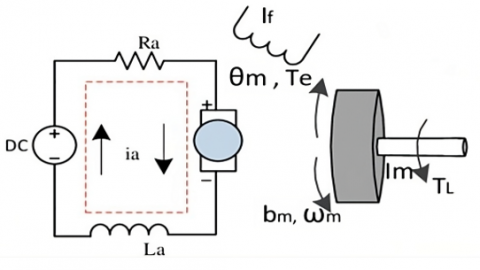
A typical actuator found in the majority of control systems is the DC motor. It transforms electrical energy into rotational motion and can also produce translational motion when combined with components like wheels and cables. The free body diagram and electrical circuit for the DC motor's rotor system are displayed in Figure 1. Table 1 lists the parameters along with their respective values. The supply voltage (V) is the system's input, and the shaft rotational speed (w) is the resultant output. The following equations show how the armature constant factor Kt links the motor torque T and armature current I, and how the motor constant Kb links the back emf (e) to the rotational velocity:
Figure 1. DC motor diagram with the electrical circuit [1]
Table 1. Parameters of DC motor
|
Parameter |
Value |
|
R |
0.5 |
|
L |
3.3 |
|
J |
0.0005 |
|
B |
0.008 |
|
Kb |
0.0027 |
|
Kt |
0.018 |
|
Ke |
0.06 |
When KVL and Newton's law are applied to the circuit, we obtain:
$\frac{d^2 \theta}{d t^2}+B \frac{d \theta}{d t}=K t i$ (3)
$L \frac{d i}{d t}+R i=V-K_b \frac{d \theta}{d t}$ (4)
Using the Laplace transform, we obtain:
$s(J s+B) \theta(s)=K t i(s)$ (5)
$(L s+R) i(s)=V-s K b \theta(s)$ (6)
$\frac{\theta}{V}=\frac{K_t}{s,(L s+R)(J s+B)+K_b K_t}$ (7)
The transfer function from input voltage to output speed (w) will be:
$\frac{w}{V}=\frac{K_t}{\left(L_s+R\right)\left(J_s+B\right)+K_b K_t}$ (8)
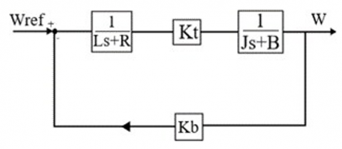
By solving and removing i(s), open-loop transfer function can be obtained, where the angle is the output, and the voltage is the input. The equivalent block diagram of an armature-controlled DC Motor based on (8) is shown in Figure 2, where, Resistance (R), Inductance (L), Motor Inertia (J), Viscous friction coefficient (B), Motor Constant (Kb), Torque constant (Kt) and Back EMF (Ke) and their values are given in Table 1.
Figure 2. DC motor equivalent block diagram [3]
2.1 PID controllers
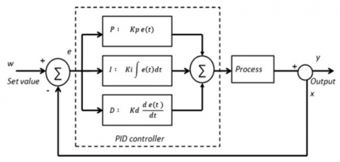
A conventional PID controller combines derivative, integral, and proportional actions simultaneously. Figure 3 depicts a PID controller's construction. By comparing the answer with the intended value, these controllers tend to reduce errors, or the difference between the process variable and setpoint. Three parameters must be specified in its design: the derivative D parameter, the integral I parameter, and the proportional P parameter. The following is a description of the parameters and the actions that go along with them (6):
Figure 3. PID closed loop system [8]
According to Table 2, The parameters for the classic PID controller were chosen by applying the Ziegler-Nichlos method, which is a heuristic tuning method, to find the initial parameters of the controller as follows:
Performing our step test for the 12V DC motor and observing the output response of the simulation, such as overshot, settling time, rising time, and overall stability.
Table 2. Ziegler-nichols method [10]
|
Controller Type |
Kp |
Ti |
Td |
|
P |
0.5 Ku |
- |
- |
|
PI |
10 Ku |
Tu/1.2 |
- |
|
Classical PID |
0.6 Ku |
0.5 Tu |
0.125 Tu |
Calculating the ultimate gain $(K u)$ by increasing the proportional gain $(K p)$ until the output oscillates with a constant amplitude and measuring the oscillation time $(T u)$.
Set up: Proportional Gain $(K p):\left(k_p=0.6 \times K_u\right)$ for a P-controller.
Integral Time $(T i):\left(T_i=\frac{T_u}{2}\right)$ for a PI-controller.
Derivative Time $(T d):\left(T_d=\frac{T_u}{8}\right)$ for a PID controller.
After fine-tuning the PID parameters based on our simulation’s response with the lowest possible overshoot and settling time, we were able to validate our selected parameters after a few iterations, and we were able to optimize the best value, which is (Kp = 10, Ki = 2, and Kd = 0.5).
$\left.u(t)\right|_{P I D}=K_P e(t)+K_i \int e(t) d t+K_d \frac{d_e}{d_t}$ (9)
The PID controller's transfer function is expressed as follows:
$\frac{U(s)}{E(s)}=G_{P I D}(s)=K_p+K i \frac{1}{S}+K_d S$ (10)
Regarding derivative time $T d$ and integral time $T i$:
$G_{P I D}(S)=K_p\left(1+\frac{1}{T_i S}+\left(T_d S\right)\right)$ (11)
Here,
$K_i=K_{p / T_i}$ (12)
$K_d=K_{p^*} T_d$ (13)
Heuristics, automated techniques, or manual tweaking can all be used to adjust these parameters. The input-output relationship is processed by a mathematical model in the automatic tuning or self-tuning method.
It is desirable to move proportional and derivative actions to the feedback (so that only the feedback signal is impacted) while keeping the integral action in the feedforward channel, given the kicking effect these actions have on a PID controller's output.
2.2 Design of sliding mode controller for DC motor
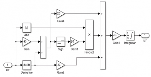
Sliding mode control's fundamental idea is to move the system's state trajectory in the direction of a surface S(X)=0 and then use the switching logic function Un to keep it there. The fundamental sliding mode control law can be written as [20] (Figure 4):
$U=U_{e q}+U_n$ (14)
Figure 4. Sliding mode control technique Simulink design
Two terms, Ueq and Un had been used as expressions, and Ueq is established offline using models that signify the plant is the most suitable.
The trajectory tracking problem consists in determining a control law u(x) which makes it possible to ensure the convergence of the state x of the system towards the desired state xd.
The selection of the SMC parameters was chosen based on understanding the system dynamics, defining the sliding surface, and designing a control law to achieve robustness and stability. The first step is to design the slide mode controller by designing the slide mode function as mentioned in Eq. (15).
Tracking error $(e)$ and the variable $(\lambda)$ must satisfy the Hurwitz condition $(\lambda>0)$ as mentioned in Eq. (16).
To guarantee the stability condition, the derivation of the Lyapunov function $\left(V=1 /(2) S^2\right)$ must be $(\tilde{V}<0)$ and (SŚ<0).
To satisfy the condition (SŚ<0), the slide mode controller is designed as (SŚ=$-\mathrm{K} \operatorname{sgn}(\mathrm{s})<0$), where:
$\operatorname{sgn}(s)=\left\{\begin{array}{cc}1 & S>0 \\ 0 & S=0 \\ -1 & S<0\end{array}\right.$
In our design, we set up $(K=10, \lambda=5)$ to achieve higher stability, zero overshoot and reducing the chattering effect of the system.
The sliding variable is:
$S=e+\lambda e$ (15)
with, $\lambda>0$.
e: The error
$e=x_d-x_1=\Omega-\Omega_{r e f}$ (16)
$\dot{e}$: The error derivative
$e=x_d-x_1$ (17)
The transfer function:
$F(p)=\frac{\Omega(p)}{U_\alpha(p)}=\frac{K_c}{j L_\alpha P^2+\left(R_\alpha j\right)+\left(L_\alpha f_r\right) P+R_\alpha f_r+K_c K_e}$
We pose:
$\begin{gathered}j L_\alpha=A \\ R_\alpha j+L_\alpha f_r=B \\ R_\alpha f_r+K_c K_e=C \\ F(p)=\frac{\Omega(p)}{U(p)}=\frac{K_c}{A p^2+B p+C}\end{gathered}$
The equation is divided on A:
$F(p)=\frac{\Omega(P)}{U(P)}=\frac{K_C / A}{P^2+B / A P+C / A}$
The formula F(p) in the time domain can be expressed as follows:
$\begin{gathered}P^2 \Omega+\frac{B}{A} P \Omega+\frac{C}{A} \Omega=\frac{K_C}{A} U \\ \ddot{\omega}+\frac{B}{A} \dot{\omega}+\frac{C}{A} \omega=\frac{K_c}{A} U \\ \ddot{\omega}=\frac{K_c}{A} U-\frac{B}{A} \dot{\omega}-\frac{C}{A} \omega \\ \dot{x}_1=x_2=\dot{\Omega}(t) \\ \ddot{x}_1=\dot{x}_2=\ddot{\Omega}(t)\end{gathered}$
When, $x_1=\omega(t)$.
After that, the system can be transformed into the canonical form shown below. Thus:
$\begin{gathered}S=\dot{e}+\lambda e \\ x_2=\frac{K_c}{A} U-\frac{B}{A} \Omega-\frac{C}{A} \Omega \\ S=\left(\dot{x}_d-\dot{x}_1\right)+\lambda\left(x_d-x_1\right)\end{gathered}$
The command that is discontinuous is issued by:
$U_n=-\alpha \frac{S}{|S|+\delta}$
Ueq found by using the relationship: S=0.
$\ddot{S}=\left(\ddot{x}_d-\ddot{x}_1\right)+\lambda\left(\dot{x}_d-\dot{x}_1\right)$
By applying values in Table 1
$\begin{aligned} & =\left[\begin{array}{l}X 1 \\ X 2\end{array}\right], A=\left[\begin{array}{cc}-\frac{\mathrm{Kb}}{j} & \frac{\mathrm{Kt}}{j} \\ -\frac{\mathrm{Ke}}{L} & -\frac{R}{L}\end{array}\right], B=\left[\begin{array}{l}0 \\ \frac{1}{L}\end{array}\right] \\ = & {\left[\begin{array}{ll}1 & 0\end{array}\right] } \\ A & =\left[\begin{array}{cc}-5.4 & 36 \\ -0.0181 & -0.1515\end{array}\right], B=\left[\begin{array}{c}0 \\ -0.3030\end{array}\right] \\ = & {\left[\begin{array}{cc}-5.4 & 36 \\ -0.0181 & -0.1515\end{array}\right] X+\left[\begin{array}{c}0 \\ 0.3030\end{array}\right] U Y } \\ = & {\left[\begin{array}{ll}1 & 0\end{array}\right] X }\end{aligned}$
By converting state model to transfer function:
$U(s) \frac{10.91}{s^2+5.552 s+1.47}$
2.3 Fuzzy logic controller
Any dynamic controller can be designed alternatively by utilizing fuzzy logic control, or FLC. Its foundation is fuzzy logic, a linguistic control method that does not rely on mathematical equations but rather on broad assertions. The fuzzy reasoning approach and a control structure with gains and rules make up FLC's architecture. to design a controller, it can make use of human expertise and experience [27].
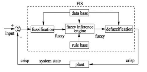
The rules that have been modified to create fuzzy control are straightforward "IF-THEN" statements rather than mathematical formulas. Figure 5 depicts the architecture of a fuzzy control system. The fuzzy control system's building blocks are:
Figure 5. Fuzzy logic modules [2]
An FLC's decision-making system is based on a set of fuzzy rules, which is known as the rule base. These rules use "IF-THEN" conditional expressions to analyze complex data sets and produce accurate results. The "Then" side is referred to as the consequence, and the "If" side is known as the antecedent or premise. One instance of a fuzzy rule is this one: a high temperature corresponds to a high fan speed.
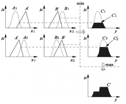
Figure 6. Mamdani fuzzy model [7]
2.3.1 Mamdani fuzzy model
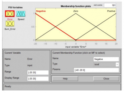
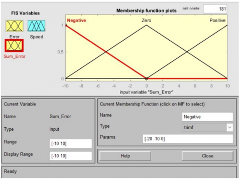
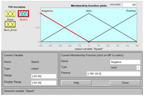
Figures 7 and 8 represent the FLC membership functions error (e) and Sum error (Sum e) as inputs respectively, while (O) refer to the output membership function as shown in Figure 9. For effective speed control, a suitable domain must be set; this domain is chosen via practice and simulation tests. The domains of e and O are, respectively, [-20, 20], [-10, 10], and [-50, 50].
Figure 7. FLC membership functions of error
Figure 8. FLC membership functions of sum error
Figure 9. FLC membership functions of output
Linguistic variables define the output space of o and the input space of e and Sum e. These variables are present in the fuzzy input and output sets. {low error (LE), medium error (ME), high error (HE)} [2, 5] defines the input e. O by {low output (LO), medium output (MO), high output (HO)} and the Sum e by {low change (LC), medium change (MC), high change (HC)}. The sensitivity and robustness were assessed using triangular membership functions. The construction of fuzzy logic rules is based on empirical observations.
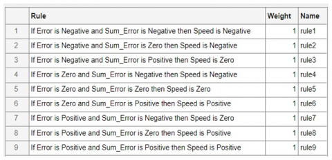
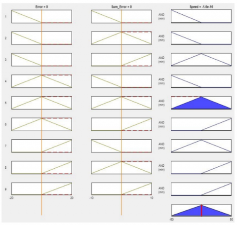
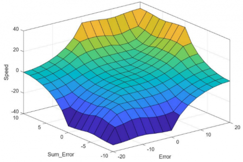
Figure 10 identify the FLC rules. These rules can be expressed as follows: (O is LO) if (e is LE) and (Sum e is LC). In the same way, the other rules can all be described. Figure 11 displays the FLC's rule viewer. In Figure 12, the control surface for fuzzy lofic control can be specified and noticed clearly.
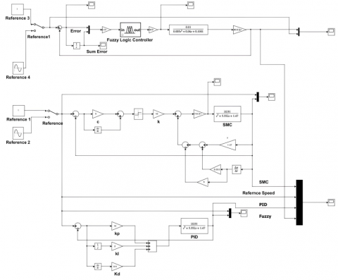
This research is a testament to the power of advanced control techniques in optimizing the performance of DC motors. The study involved designing three cutting-edge control methods - Proportional Integral Derivatives (PID), Fuzzy Logic Control (FLC), and Sliding Mode Control (SMC) - using MATLAB Simulink and the mathematical model of the motor as can be noticed in Figure 13.
By analyzing the behavior and results of each technique, the study provides valuable insights into the most effective means of controlling the motor's speed.
Figure 10. FLC’s rules
Figure 11. FLC’s rules viewer
Figure 12. Control surface for FLC
Figure 13. DC motor control model design via Matlab Simulink
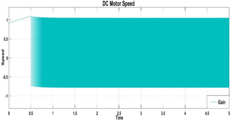
As can be seen from the result in Figure 14 when the motor is running in an open loop (depicted by the black line), about 20% offset error is present as the responses are limited to around 80%. This problem is resolved when the motor is operated in a closed-loop system having different controllers.
Figure 14. DC motor gain
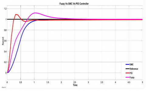
For effective comparison, the system is simulated at speeds of 5 sec their simulation result is shown in Figure 15. As it can be noticed that:
Figure 15. Output response characteristics for FLC, SMC and PID
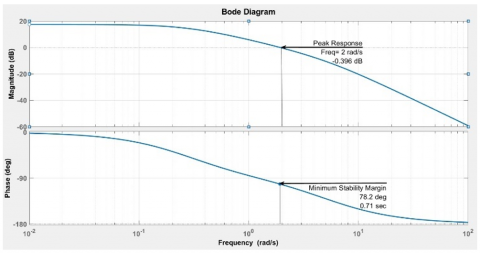
Figure 16. Bode plot for DC motor
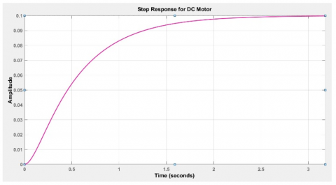
Figure 17. Step response for DC motor
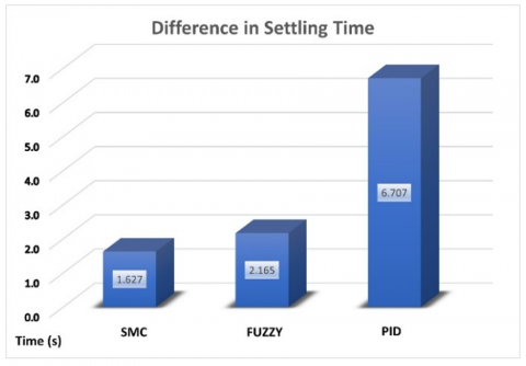
Figure 18. Settling time for SMC, fuzzy and PID
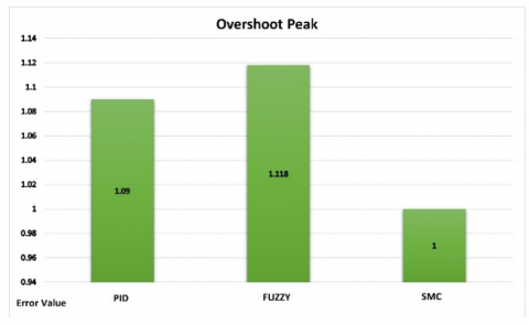
Figure 19. Maximum overshoot value for FLC, SMC and PID
DC motor’s performance influenced by the three control techniques mentioned previously in practical applications such as:
Table 3. Difference in DC motor controllers’ behavior
|
No. |
Control Technique |
PID |
FLC |
SMC |
|
1 |
Rise Time |
1.422 |
1.135 |
0.593 |
|
2 |
Settling Time |
6.707 |
2.165 |
1.627 |
|
3 |
Overshoot |
1.09 |
1.118 |
1 |
PID controllers offer precise speed control in robotics and conveyor systems. Tuning the PID controller minimizes steady-state error and overshoot. Electric vehicles and lifting mechanisms benefit from a short rise time and minimized overshoot and settling time.
PID controllers are simple and effective, but may not be the most robust option in handling system uncertainty and large disturbances. They require careful parameter tuning (Kp↑, Td↑, 1/T1↑) for getting perfect Rise Time, Settling Time and Overshoot value.
Fuzzy logic control (FLC) is ideal for Electric Vehicles, Robotics, and Conveyor Systems. FLC ensures precise throttle control, smooth acceleration, and responsive motor control for manipulation and navigation. FLC also maintains consistent speed while preventing product damage due to sudden starts or stops.
Also (FLCs) excel at handling system uncertainties and non-linearities. They are more robust than PID controllers when it comes to disturbances and parameter changes. FLCs has model design (Mamdani Fuzzy Model) by using Simulink/MATLAB, when the fuzzy logic controller receives error (e) and Sum error (Sum e) as inputs, and (O) is the output. For effective speed control, a suitable domain must be set; this domain is chosen via practice and simulation tests.
SMC can have a significant impact on DC motor speed control in industrial automation. It ensures consistent speed control for conveyor belts and assembly lines, guarantees robustness and accuracy for Electric Vehicles, and provides precision and quick response for Robotics.
SMC is a robust control method that maintains the system state on a sliding surface, making it effective in high-uncertainty environments. Although it may suffer from chattering, SMC offers excellent performance in systems with non-linearity and parameter variations when sliding mode control guides a system's state trajectory towards S(X)=0 using Un and Ueq. The control law u(x) ensures that the system's state converges to the desired state xd.
Table 4 compares three closed-loop control methods based on their time response characteristics. Sliding mode control (SMC) outperforms the others, offering superior set-point tracking, faster response speed, and the lowest overshoot value.
Table 4. Result analysis for different controllers
|
No. |
Controller Technique |
Strengths |
Weaknesses |
|
1 |
FLC |
Reasonable settling time |
Significant overshoot value |
|
2 |
SMC |
Faster response and less settling time |
Unstable at higher set point, and logic needs to be manipulated due to the chattering effect |
|
3 |
PID |
Acceptable overshoot |
Has longer settling time |
This study presents an improved DC motor speed control system that utilizes fuzzy logic, PID, and sliding mode controllers. The fuzzy logic control can be adjusted to improve rise time (1.135), but this will result in a longer settling time (2.165) and increased overshoot (1.118). The output of the PID controller results in a slow settling time of (6.707) and a rising time of (1.422). However, it is worth mentioning that this controller produces an average overshoot value of (1.09).
The SMC controller is the right choice for high-quality output and resilient performance in the presence of disturbances or variations because it offers excellent output quality and eliminates the need for any tuning. The SMC is a highly effective controller that delivers superior output quality compared to its relatively fast rising time (0.593) and settling time (1.627). It is especially useful in scenarios where speed control is critical, owing to its ability to overshoot with a value of (0.593). Therefore, if you are looking for a dependable and efficient controller that meets your requirements, the SMC is the ideal option.
Based on the data analysis, it has been found that PID and FLC are not efficient in delivering the optimal control for the same reference signal and time. Therefore, when modifying the logic of FLC and PID, the set point needs to be considered. In contrast, sliding mode control has shown great potential in tracking and speed regulation performance. It has a fast response speed with low overshoot and no static error, making it an effective control method. Additionally, it has several strengths, including its quick response time and ease of deployment, as well as its ability to withstand both internal and external interruptions. In summary, this controller achieves:
Future research on DC motor speed control recommends hybrid approaches that merge fuzzy logic, PID, and SMC. These techniques have the potential to improve DC motor speed control strategies by offering superior performance, adaptability, and speed tracking with reduced rise and settling time, zero overshoot, and steady-state inaccuracy. For producing superior control and efficiency, it is highly recommended to integrate fuzzy logic with predictive PIDs, fuzzy self-tuning PID controllers, and adaptive fuzzy-PID controllers.
[1] Hafez, A.T., Sarhan, A.A., Givigi, S. (2019). Brushless DC motor speed control based on advanced sliding mode control (SMC) techniques. In 2019 IEEE International Systems Conference (SysCon), Orlando, FL, USA, pp. 1-6. https://doi.org/10.1109/syscon.2019.8836754
[2] Lotfy, A., Kaveh, M., Mosavi, M.R., Rahmati, A.R. (2020). An enhanced fuzzy controller based on improved genetic algorithm for speed control of DC motors. Analog Integrated Circuits and Signal Processing, 105: 141-155. http://doi.org/10.1007/s10470-020-01599-9
[3] Yadav, S.L., Karvekar, S.S. (2022). Design of integral sliding mode controller for speed control of induction motor. In 2022 2nd International Conference on Intelligent Technologies (CONIT), Hubli, India, pp. 1-6. http://doi.org/10.1109/conit55038.2022.9847959
[4] Samantaray, J., Chakrabarty, S. (2018). Implementing sliding mode control of DC servo motor over a control network. In 2018 Indian Control Conference (ICC), Kanpur, India, pp. 358-362. http://doi.org/10.1109/indiancc.2018.8308005
[5] Almatheel, Y.A., Abdelrahman, A. (2017). Speed control of DC motor using fuzzy logic controller. In 2017 International Conference on Communication, Control, Computing and Electronics Engineering (ICCCCEE), Khartoum, Sudan, pp. 1-8. http://doi.org/10.1109/iccccee.2017.7867673
[6] Azizah, D.F., Dedes, K., Utama, A.B.P. (2021). DC motor speed modeling and simulation using fuzzy logic control method. In 2021 7th International Conference on Electrical, Electronics and Information Engineering (ICEEIE), Malang, Indonesia, pp. 279-284. http://doi.org/10.1109/iceeie52663.2021.9616636
[7] Bharadwaj, S. (2015). Comparative analysis of speed control techniques of DC motors with matlab. International Journal of Engineering Research & Technology, 4(5): 672-675. http://doi.org/10.17577/ijertv4is050798
[8] Sadeghi, M.S., Varzandian, S., Barzegar, A. (2011). Optimization of classical PID and fuzzy PID controllers of a nonlinear quarter car suspension system using PSO algorithm. In 2011 1st International eConference on Computer and Knowledge Engineering (ICCKE), Mashhad, Iran, pp. 172-176. http://doi.org/10.1109/iccke.2011.6413346
[9] Hassan, A.A., Al-Shamaa, N.K., Abdalla, K.K. (2017). Comparative study for DC motor speed control using PID controller. International Journal of Engineering and Technology, 9(6): 4181-4192. http://doi.org/10.21817/ijet/2017/v9i6/170906069
[10] Ziegler, J.G., Nichols, N.B. (1942). Optimum settings for automatic controllers. Transactions of the American Society of Mechanical Engineers, 64(8): 759-765. http://doi.org/10.1115/1.4019264
[11] Ziegler, J.G., Nichols, N.B. (1943). Process lags in automatic-control circuits. Transactions of the American Society of Mechanical Engineers, 65(5): 433-440. http://doi.org/10.1115/1.4018788
[12] Tepljakov, A., Gonzalez, E.A., Petlenkov, E., Belikov, J., Monje, C.A., Petráš, I. (2016). Incorporation of fractional-order dynamics into an existing PI/PID DC motor control loop. ISA Transactions, 60: 262-273. http://doi.org/10.1016/j.isatra.2015.11.012
[13] Ji, J.K., Sul, S.K. (1995). DSP-based self-tuning IP speed controller with load torque compensation for rolling mill DC drive. IEEE Transactions on Industrial Electronics, 42(4): 382-386. http://doi.org/10.1109/41.402477
[14] Borase, R.P., Maghade, D.K., Sondkar, S.Y., Pawar, S.N. (2021). A review of PID control, tuning methods and applications. International Journal of Dynamics and Control, 9: 818-827. http://doi.org/10.1007/s40435-020-00665-4
[15] George, T., Ganesan, V. (2022). Optimal tuning of PID controller in time delay system: A review on various optimization techniques. Chemical Product and Process Modeling, 17(1): 1-28. http://doi.org/10.1515/cppm-2020-2001
[16] Ang, K.H., Chong, G., Li, Y. (2005). PID control system analysis, design, and technology. IEEE Transactions on Control Systems Technology, 13(4): 559-576. http://doi.org/10.1109/tcst.2005.847331
[17] Puangdownreong, D., Nawikavatan, A., Thammarat, C. (2016). Optimal design of I-PD controller for DC motor speed control system by cuckoo search. Procedia Computer Science, 86: 83-86. http://doi.org/10.1016/j.procs.2016.05.021
[18] Rigatos, G., Siano, P., Wira, P., Sayed-Mouchaweh, M. (2016). Control of DC-DC converter and DC motor dynamics using differential flatness theory. Intelligent Industrial Systems, 2: 371-380. http://doi.org/10.1007/s40903-016-0061-x
[19] Hu, B., Mann, G.K., Gosine, R.G. (1999). New methodology for analytical and optimal design of fuzzy PID controllers. IEEE Transactions on fuzzy systems, 7(5): 521-539. http://doi.org/10.1109/91.797977
[20] King, P.J., Mamdani, E.H. (1977). The application of fuzzy control systems to industrial processes. Automatica, 13(3): 235-242. http://doi.org/10.1016/0005-1098(77)90050-4
[21] Li, H.X., Zhang, L., Cai, K.Y., Chen, G. (2005). An improved robust fuzzy-PID controller with optimal fuzzy reasoning. IEEE Transactions on Systems, Man, and Cybernetics, Part B (Cybernetics), 35(6): 1283-1294. http://doi.org/10.1109/tsmcb.2005.851538
[22] Li, H.X., Tso, S.K. (2000). Quantitative design and analysis of fuzzy proportional-integralderivative control a step towards autotuning. International Journal of Systems Science, 31(5): 545-553. http://doi.org/10.1080/002077200290867
[23] Guo, Y., Mohamed, M.E.A. (2020). Speed control of direct current motor using ANFIS based hybrid PID configuration controller. IEEE Access, 8: 125638-125647. http://doi.org/10.1109/access.2020.3007615
[24] Kim, J.H., Lee, S.W., Kim, K.C., Chong, E.K.P. (1993). Fuzzy precompensation of PID controllers. In Proceedings of IEEE International Conference on Control and Applications, Vancouver, BC, Canada, pp. 183-188. http://doi.org/10.1109/CCA.1993.348284
[25] Jiang, Y., Fu, G., Liang, Z. (2022). Research on speed control of sensorless brushless DC (BLDC) motors based on improved fuzzy-PI control. In Proceedings of the 2022 2nd International Conference on Control and Intelligent Robotics, Nanjing, China, pp. 49-53. http://doi.org/10.1145/3548608.3561138
[26] Doğruer, T. (2023). Fractional order PID controller design and robustness analysis for speed control of DC Motor. Adıyaman Üniversitesi Mühendislik Bilimleri Dergisi, 10(19): 15-28. http://doi.org/10.54365/adyumbd.1152949
[27] Yoldaş, K., Tekin, A., Boztepe, M. (2019). An improved speed controller for PMSM drive with unbalanced load using load torque observer. In 2019 IEEE Texas Power and Energy Conference (TPEC), College Station, TX, USA, pp. 1-6. http://doi.org/10.1109/tpec.2019.8662181
[28] Tajudin, A.I., Izani, M.A.D., Abd Samat, A.A., Omar, S., Idin, M.A.M. (2022). Design a speed control for DC motor using an optimal PID controller implementation of ABC algorithm. In 2022 IEEE 12th International Conference on Control System, Computing and Engineering (ICCSCE), Penang, Malaysia, pp. 97-102. http://doi.org/10.1109/iccsce54767.2022.9935644
[29] Abd Samat, A.A., Subani, M.A., Ab Aziz, N.F., Salim, N.A., Daud, K., Tajudin, A.I. (2022). PSO-based PI controller for speed control of DC motor. In 2022 IEEE International Conference on Power and Energy (PECon), Langkawi, Kedah, Malaysia, pp. 481-486. http://doi.org/10.1109/pecon54459.2022.9988840
[30] Bodur, F., Kaplan, O. (2023). Integral sliding mode control with improved reaching law for brushless DC motor speed control. In 2023 11th International Conference on Smart Grid (icSmartGrid), Paris, France, pp. 1-7. http://doi.org/10.1109/icsmartgrid58556.2023.10170889
[31] Kheel, A.M., Al-Shamaa, N.K., Hawas, M.N. (2023). Sliding mode controller enchancement for speed control of BLDC motor based on dragonfly algoritm. In 2023 International Conference on Converging Technology in Electrical and Information Engineering (ICCTEIE), Bandar Lampung, Indonesia, pp. 135-141. http://doi.org/10.1109/iccteie60099.2023.10366754
[32] Poornesh, K., Mahalakshmi, R., Reddy, G. (2022). Speed control of BLDC motor using fuzzy logic algorithm for low cost electric vehicle. In 2022 International Conference on Innovations in Science and Technology for Sustainable Development (ICISTSD), Kollam, India, pp. 313-318. http://doi.org/10.1109/icistsd55159.2022.10010397
[33] Patil, A., Jadhav, S. (2023). Fuzzy logic controller implementation for BLDC drive speed control using FOC approach and SVPWM based VSI technique. In 2023 3rd Asian Conference on Innovation in Technology (ASIANCON), Ravet IN, India, pp. 1-5. http://doi.org/10.1109/asiancon58793.2023.10269999