Kavitha Hosakote Shankara![]() | Mallikarjunaswamy Srikantaswamy*
| Mallikarjunaswamy Srikantaswamy*![]() | Sharmila Nagaraju
| Sharmila Nagaraju![]()
© 2024 The authors. This article is published by IIETA and is licensed under the CC BY 4.0 license (http://creativecommons.org/licenses/by/4.0/).
OPEN ACCESS
This paper presents a comprehensive survey on the use of artificial neural networks (ANN) for enhancing DC-DC converters in renewable energy systems, focusing on equal current sharing and voltage stability amidst the growing scarcity of electricity. The survey methodically examines literature on ANN integration with DC-DC converters, selecting studies based on their relevance to managing renewable energy efficiently, improving power distribution, and the effectiveness of ANN in addressing these challenges. The research identifies several gaps, including optimal power distribution, predictive controller limitations, and the instability of proportional-integral (PI) controls due to online training algorithm adjustments. To bridge these gaps, an innovative ANN-based control method for DC-DC converters is proposed, aimed at bolstering power generation quality, enabling flexible power distribution across microgrids, and enhancing the stability, reliability, and cost-effectiveness of renewable energy sources. Moreover, the paper discusses the correction of offline training problems, feedback error signal corrections, and integral error signals of DC-DC converters, offering new insights and solutions to overcome these technical barriers. This study underscores the converter's size and integration significance, juxtaposing traditional methods with ANN-based controls to highlight the latter's performance and efficiency advantages. Through a detailed review and proposed solutions to significant challenges in renewable energy management, this work contributes to the field's advancement by enhancing the efficiency and reliability of power systems through cutting-edge ANN-based control methods.
DC-DC converter, hybrid microgrid, super capacitor, photo voltaic (PV), Dual active bridge DC-DC converter, artificial neural network (ANN)
Energy sources such as renewable energy and storage units for storing hybrid energy are present in DC microgrids. Therefore, it is necessary to control power fluctuations within the system and improve power quality using energy management methods [1]. In renewable energy sources, many switching devices are used to reduce harmonics and switching losses, thereby improving the system's reliability [2]. This work presents strategies for energy management in microgrids and technologies for grid integration. With the goal of providing clean energy in the future and reducing costs, renewable energy-based power generation systems are considered the best option and are rapidly advancing to meet requirements [3]. Photovoltaic systems offer a direct platform for converting solar energy into electrical energy. Solar power is converted into electrical power by PV systems and integrated with the grid if grid codes are satisfied [4]. Energy sources such as wind turbines, battery energy storage systems, DC loads, and grid-connected converter systems are present in the DC microgrid. In the renewable energy sector, Solar PV technologies are best suited for hills, islands, and forest areas.
Transportation facilities and minimal communication, along with poor technical knowledge, are significant challenges. To maximize the benefits from solar energy, power electronics circuits are effectively used for grid integration [5]. A suitable DC-DC converter is essential for both the Solar PV and the load to enhance the system's efficiency [6]. In solar PV systems, the application of multiple converters is designed to increase voltage gain. With multiphase interleaved DC-DC converters, less ripple and better dynamic response are achieved, improving efficiency. This work presents a converter based on the combination of CUK and SEPIC for connecting distributed generation to power architecture and bipolar DC microgrids [7]. To provide high gain, switched capacitors and inductors are utilized in the system. The devices in the system experience the same voltage stress, which helps in utilizing devices with minimal internal resistance and uniform ratings [8].
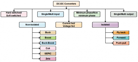
To ensure electrical isolation, traditional Buck/Boost circuits are used instead of multi-port isolated DC-DC converters [9]. The drawbacks of the topology of boost DC-DC converters include the requirement for large capacitors, high power levels of parallel devices, a voltage gain of less than 4:1, and a high ripple rate [10, 11]. The topology of DC-DC converters plays a significant role in the power-generating industry due to low production costs, minimal size, and high conversion efficiency. The topologies of DC-DC converters are classified into non-isolated and isolated categories [12, 13]. Figure 1 shows the general classification methods for DC-DC converters. In PV systems, the traditional boost converter is used and is required to operate at a duty cycle of 0.88. In practical applications, maintaining this duty cycle is challenging due to the limitations of semiconductor devices. Often, the boost converter suffers from reverse recovery issues and the drawback of high switching voltage stress [14].
Figure 1. DC-DC converters general classification methods
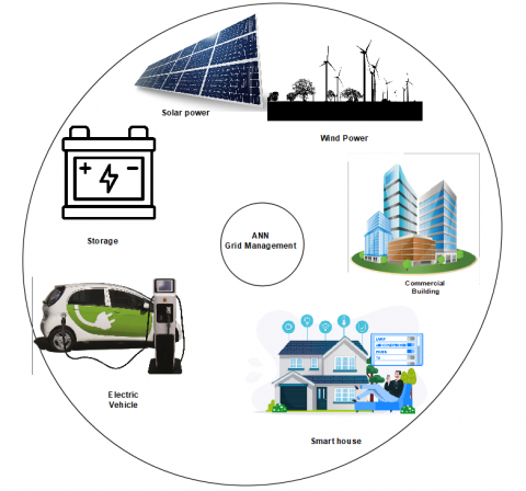
Figure 2. The applications of smart grid system
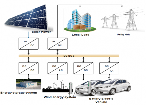
Figure 3. A charging station with simplified hybrid microgrid represents battery powered electric vehicles
Figure 2 summarizes the applications of the smart grid system. The function of the grid remains largely the same as it was historically, with only minor improvements, and the cost of energy was relatively low. Currently, there is no technology available to store electricity on a large scale. Hence, an effective system can be built during off-peak hours. However, the efficiency of the grid can be increased by adjusting load consumption, which is a key difference between smart grids and traditional grids. Higher power converters and transformers are required for these conversions. These converters cannot use a single topology. For instance, Full-bridge, Push-pull, and Half-bridge converters fall under the category requiring a minimum of multi-switch configurations among other DC-DC isolated converters. Figure 3 shows a charging station within a simplified hybrid microgrid, representing battery-powered electric vehicles.
In various applications, PV technology can be utilized, such as in microgrids, domestic settings, and electric vehicles [15]. DC-DC converters, operating at different voltage levels and linked to the PV system, are addressed. This also involves identifying suitable load types and grid-connected mode converters, along with their conversion efficiency and voltage gain. In grid-connected PV applications, 14 types of DC-DC converters are reviewed. The performance of these converters is compared across different grid-connected PV systems with distributed energy sources and operating modes. Furthermore, a comparison of component sizing and an analysis of each converter's parameters are conducted to identify the drawbacks of each converter in specific modes of operation for particular applications.
1.1 Background
This paper embarks on an extensive exploration of DC-DC boost converter techniques and Artificial Neural Network (ANN) DC-DC converters amidst a burgeoning demand for efficient, reliable, and stable renewable energy systems. The integration of solar photovoltaic (PV) systems into the grid necessitates advanced conversion techniques to manage voltage gain and mitigate voltage stress, essential for optimizing energy harvest and minimizing grid instability.
1.2 Problem statement
Despite significant advancements in DC-DC conversion technology, challenges persist in ensuring high efficiency, reliability, and stability in the face of dynamic solar PV outputs and grid demands. Traditional converters and even some modern methodologies fall short in addressing voltage stress factors efficiently, leading to potential grid synchronization issues and compromised system performance. Moreover, the increasing complexity of renewable energy systems calls for smarter, more adaptive solutions to manage the intricacies of power conversion, distribution, and storage.
1.3 Objectives
The primary objective of this paper is to conduct a comprehensive survey and analysis of existing DC-DC boost converter techniques, with a particular focus on ANN-based converters, to identify and evaluate their efficacy in solar PV applications. Specific goals include:
The aim is to identify and propose solutions that improve the adaptability and efficiency of DC-DC converters in renewable energy systems, particularly solar PV setups.
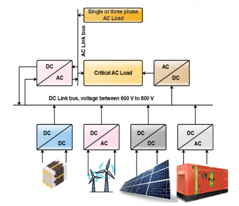
In a PV-based power supply system, the topologies used in DC-DC converters are presented in the subsequent paragraphs. Figure 4 shows the typical layout of a DC microgrid. DC-DC converters are used to obtain the desired DC voltage value without increasing the stack size. For example, the DC output of a polymer electrolyte membrane (PEM) is around several tens of volts. Hence, due to the switching of the DC-DC converter, the ripple current value should be as low as possible. It is also important to avoid large magnitudes of high-frequency current ripple and prevent sharp falls or rises in the current [16].
Figure 4. DC microgrid layout
Table 1 presents an overview of current technology in PV-based power generation using isolated DC-DC converters. An analysis of the literature was included in the study to understand viewpoints and current achievements in this field. Although several research papers have been published, they have not addressed the efficacy achieved and the complexity of implementation. With the available published literature, a comparison of DC-DC converters in terms of high voltage gains and corresponding solutions is addressed.
Table 1. Observations of hybrid converters
|
SI. No |
Supply Direction |
Particular Converter |
Different ASD |
Description |
|
1. |
Bidirectional |
Boost |
Supercapacitor |
Boost converter is not considered in model and it facing start-up problem. |
|
2. |
Bidirectional |
Boost |
Supercapacitor |
Simulation process required load transient and boost converter is not consider in the model and it is facing start-up problem. |
|
3. |
Bidirectional |
Boost |
Supercapacitor |
The boost converter builds by complex control and this system facing start-up problem. |
|
4. |
Bidirectional |
Boost |
Supercapacitor |
The boost converter builds by complex control and this system facing start-up problem. |
|
5. |
Bidirectional |
Buck-boost |
Supercapacitor and batteries |
The buck-boost module is built by complex controller and also connected with an FC. |
|
6. |
Unidirectional |
Buck-boost |
Supercapacitor |
The buck-boost module is built by simple and it is capable to operate all the modes in the system. |
DC-DC converters are electronic devices used to convert one direct current (DC) voltage level to another. They play a crucial role in various applications, including power supplies, battery charging, renewable energy systems, and more. There are several different topologies of DC-DC converters, each with its unique advantages and disadvantages. Below are some of the most common topologies:
3.1 Topology of coupled inductor
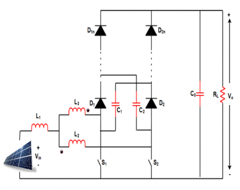
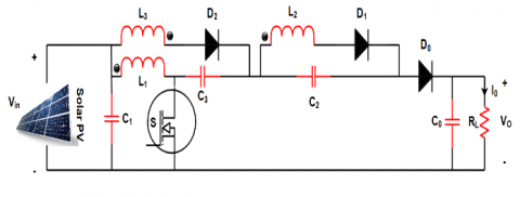
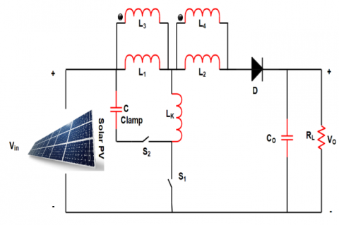
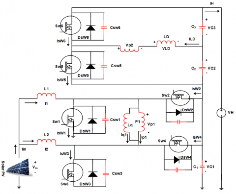
Figures 5-8 show the different topology for coupled inductor published in the literature. The topology published in the literature explain the converter power range and Vin and Vout range for setup the experiment. The DC-DC converter proposed in the study [17] has exhibits soft switching with a high voltage gain and continuous input current. The experimental results show that it was provide the efficiency of 96% At full load of Vout = 360 V with Vin = 24 V. Having the Winding-Cross-Coupled Inductors (WCCIs) is the one of the derived interleaved boost converter advantages. Also, when compared traditional interleaved boost converters the advantage of passive-lossless clamp circuits are provides the reduced reverse recovery, reduced switching voltage stress, and increased voltage gain [18]. At full load an interleaved boost converter it provides 40 V to 380V at rated of 1kW and efficiency of 90.7% which is 5% higher than the traditional interleaved boost converters [19]. A high voltage gain is achieved with coupled inductor of three-winding.
Figure 5. Inductor 1 coupled
Figure 6. Inductor 2 coupled
Figure 7. Inductor 3 coupled
Figure 8. Inductor 4 coupled
The switching stress is directly reduced to the output in the leakage inductor energy. A coupled inductor is used to evaluate the reverse recovery current of output diodes. An efficiency of 95.2% is obtained with Fs = 100 kHz, Vin = 27 V–36.5 V, and Vout = 400 V in the closed-loop control method. The coupled inductors in a 200W boost converter and active clamps in a buck-boost reduce the converter’s size, achieve three-stage switching, and obtain an efficiency of 97% with conduction losses [20, 21].
To boost the voltage value, it is necessary to have a high step-up DC-DC converter that generates a bus voltage of PV 400V. To limit the voltage stress and improve efficiency, the technology of passive loss is used. It is possible to recycle the leakage energy. The drawbacks of basic boost converters include the hard switching of semiconductor elements, high voltage stress, and electromagnetic interference [22]. The non-inverting voltage can be stepped down or stepped up using a DC-DC buck-boost converter with a coupled inductor, which helps in regulating the input and output currents and obtaining high efficiency [23].
3.2 Non-isolated interleaved topology
The topology of non-isolated DCDC converter is discussed in this section to provide solution to obtain the high gain problem. In this type of converter non-isolated DC-DC are used the voltage multiplier technique to provide the high step-up static gain [24]. The output of 400V is obtained with the applied input of 24V. During this process converter operated with switching frequency of 40 KHz and it provide the 95% efficiency. The losses of commutation and low electromagnetic interference is achieved without power transformer and high gain is also obtained. An output of 380V is obtained for the input of 48V and provide the efficiency of 94.1%. Figure 9 shows the interleaved converter of Inductor-Inductor-Capacitor (LLC) to obtain the high gain. It operates in the two modes of operation simultaneously and independently [25]. It operates simultaneous mode at the same frequency, and independent mode operate with single converter.
The combined mode changing and frequency control are two possible ways to increase the range of Vout [26]. The efficiency of the interleaved switched DC-DC converter is improved using the phase-shedding technique. The interleaved configuration and modular characteristics of the converter help achieve high voltage gain [27]. Figure 10 shows the typical schematic layout of a DC-DC converter.
The techniques of ZCS (Zero Current Switching) and ZVS (Zero Voltage Switching) are used to operate all the switches and diodes in the interleaved DC-DC converter with full soft-switching. To improve the efficiency of DC-DC converters and reduce power loss, ZCS and ZVS methods are employed. To avoid the switches' voltage stress and high current, the main power path is bypassed by placing an auxiliary circuit [28]. Figure 11 shows the schematic circuit diagram of the interleaved high step-up converter.
Figure 9. Topology of non-isolated interleaved
Figure 10. Typical schematic layout of DC-DC converter
Figure 11. Interleaved converter based high step-up
Table 2. Analysis of the performance interleaved converters
|
SI. No |
Reference |
Parameter |
Range and Model |
|
1. |
High Voltage Gain Interleaved DC-DC Converter with Minimum Current Ripple |
Number diode |
4 |
|
Number of windings |
4 |
||
|
Voltage gain |
$\left(\frac{2(n+2)}{1-D}\right)$ |
||
|
The voltage stress on the switches (n = 1) |
$\frac{V_0}{6}$ |
||
|
2. |
Three-Winding High- Frequency Coupled Inductor and Voltage Multiplier Cell |
Number diode |
4 |
|
Number of windings |
6 |
||
|
Voltage gain |
$\left(\frac{2 n+1}{1-D}\right)$ |
||
|
The voltage stress on the switches (n = 1) |
$\frac{V_0}{4}$ |
||
|
3. |
High Step-Up Converter with a Voltage Multiplier Module |
Number diode |
4 |
|
Number of windings |
4 |
||
|
Voltage gain |
$\left(\frac{2(n+1)}{1-D}\right)$ |
||
|
The voltage stress on the switches (n = 1) |
$\frac{V_0}{4}$ |
||
|
4. |
High Step-up Interleaved Forward-Flyback Boost Converter with Three-Winding Coupled Inductors |
Number diode |
4 |
|
Number of windings |
6 |
||
|
Voltage gain |
$\left(n_2+\frac{2 n_3 D+2-D}{1-D}\right)$ |
||
|
The voltage stress on the switches (n = 1) |
$\frac{V_0}{3}$ |
The interleaved boost converter is more advanced than the classical boost converter in terms of low input ripple current, high efficiency, high reliability, and reduced electromagnetic emissions. An efficient FC (Fuel Cell) power system is a suitable design for interleaved boost converters. Table 2 summarizes the performance analysis of interleaved converters.
3.3 Isolated push-pull boost converter
The solution presented in the literature for improving the gain of DC-DC converters, specifically the isolated push-pull boost converter topology, is discussed in this section [29]. A hard-switched type push-pull boost converter is proposed. In the proposed converter, a voltage clamp is implemented on both the primary and secondary sides of the isolation transformer. An H-bridge DC-AC converter is used after the front end in the push-pull converter. The converter produces an output of 350–400 V from an applied input of 25–45 V and provides an efficiency of 91%. With the inclusion of the H-bridge, the proposed converter achieves an efficiency of 92.5% and produces an output of 35V from an input of 30V.
3.4 Topology of fly back converter
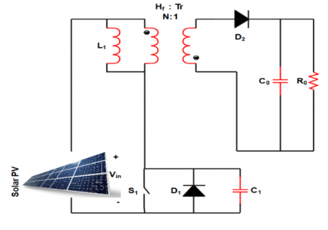
Figures 12 and 13 show the topology of the Fly-back converter and published solutions to improve the gain. In the proposed converter of the study [30], an active clamp is implemented on the main side of the transformer and a voltage multiplier on the secondary side. It produces an output of 400V for the applied input range of 25-35V. Due to the resonant phases, it reduces the circulating current through the active clamp between the parasitic capacitances of the diode and the leakage inductances of the transformer.
Figure 12. Topology of boost fly-back converter
Figure 13. Boost fly-back converter active clamp
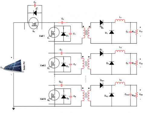
The efficiency of the converters ranges between 92% to 94% for the entire input range and provides an output power of 300W. In the study [31], a high-current energy source and low-voltage converter with a high step-up ratio of 300W are proposed. The topology of the integrated boost-flyback (IBF) includes a clamping diode that naturally produces oscillations. The resonance caused by parasitic components helps to improve the voltage gain. It produces an output of 400V for the applied input range of 25-35V. Table 3 summarizes the evaluation of various parameters. Figure 14 shows the topology of a stacked, multiple-output design of asymmetrical forward cells.
Table 3. DC-DC converters various parameter analysis
|
SI. No |
Reference |
Parameter |
Range and Model |
|
1. |
High Voltage Gain Interleaved DC-DC Converter with Minimum Current Ripple |
MOSFET voltage stress |
$\frac{V_0}{1+2 N-N D}$ |
|
The voltage stress on output diode |
$\frac{N V_0}{1+2 N-N D}$ |
||
|
Diodes |
3 |
||
|
MOSFET Soft switching |
ZVS |
||
|
No. of MOSFETs |
2 |
||
|
Soft switching of diodes |
ZCS |
||
|
Number of magnetic components |
1 |
||
|
Voltage gain |
$\frac{1+2 N-N D}{1-D}$ |
||
|
2. |
Three-Winding High-Frequency Coupled Inductor and Voltage Multiplier Cell |
MOSFET voltage stress |
$\frac{V_0}{2(1+N)}$ |
|
The voltage stress on output diode |
$\frac{V_0}{2}$ |
||
|
Diodes |
4 |
||
|
MOSFET Soft switching |
ZVS |
||
|
No. of MOSFETs |
2 |
||
|
Soft switching of diodes |
Hard switching |
||
|
Number of magnetic components |
1 |
||
|
Voltage gain |
$\frac{2(1+N)}{1-D}$ |
||
|
3. |
High Step-Up Converter with a Voltage Multiplier Module |
MOSFET voltage stress |
$\frac{V_0}{(1+N)}$ |
|
The voltage stress on output diode |
$\frac{N V_0}{1+2}$ |
||
|
Diodes |
3 |
||
|
MOSFET Soft switching |
ZVS |
||
|
No. of MOSFETs |
1 |
||
|
Soft switching of diodes |
Hard switching |
||
|
Number of magnetic components |
1 |
||
|
Voltage gain |
$\frac{1+N}{1-D}$ |
||
|
4. |
High Step-up Interleaved Forward-Flyback Boost Converter with Three-Winding Coupled Inductors |
MOSFET voltage stress |
$\frac{V_0}{2}$ |
|
The voltage stress on output diode |
$\frac{V_0}{2}$ |
||
|
Diodes |
2 |
||
|
MOSFET Soft switching |
ZVS |
||
|
No. of MOSFETs |
2 |
||
|
Soft switching of diodes |
Hard switching |
||
|
Number of magnetic components |
1 |
||
|
Voltage gain |
$\frac{1+2}{1-D}$ |
The efficiency of the converter is 94% at a frequency of 100 kHz of operation and produces an output power of 300W. For N outputs, 2N primary switches are required. The circuit shown above, with N output voltages on the secondary side, requires N + 1 primary switches [32-38].
Figure 14. Stacked multiple output topology with asymmetrical forward cells
3.5 Topology of half bridge converter
In the study [39], boost converters with a two-inductor concept were introduced. This version, an advancement of the previously mentioned boost converter topology, is dubbed the HY-Bridge rectifier. Several authors in the literature have presented two-inductor boost converters for high-power, low-Vin applications [40-48]. Figure 15 illustrates half-bridge converters of isolated boost converters with two inductors. A half-bridge LLC resonant DC-DC converter produces an output of 400V for the applied input range of 24-28V [49]. Experimental results observed an efficiency of 90.2% under full load conditions. A half-bridge circuit produces an output of 380V for the input range of 28-43V with an isolated current fed of 1.2kW [50]. The proposed converter topologies provide an overall efficiency of 94% with better component utilization.
Figure 15. Half bridge converter
3.6 Resonant converters
The series resonant converter (SRC) topology is shown in Figure 16. In the study [51], the circuit uses a parallel tank combination of (L-C) || L with high-frequency switches. The important features of the presented converter include: a) achieving better efficiency under conditions like varying line and load, b) achieving soft switching ZVS over a wide range, and c) maintaining the input current variation switches with no load current changes.
Figure 16. Having inductive output filter with series resonant converter
An inductive output filter configuration adopted by a converter of a full-bridge phase-shifted is shown in Figure 17. For high-power applications, this configuration of a soft-switched converter is widely used [52-55]. The proposed configuration of the converter realizes ZVS using a constant frequency capable of primary main switches with minimal circulating circuit configuration. The important characteristics of the proposed converter are:
Figure 17. Full bridge converter with phase shifted
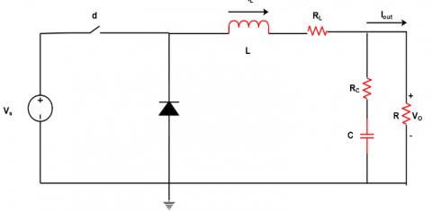
The author has proposed an artificial neural network for monitoring the asymmetric half-bridge DC-DC converter, used for the analysis of sensitivity applications. The proposed method, as shown in Figure 18, efficiently identifies power electronics fluctuations by monitoring the input and output processes of the DC-DC converter. Apart from this, it is capable of focusing on many sensitive power electronics applications. The proposed algorithm mainly concentrates on the DC-DC converter. The proposed method is not applicable for renewable energy resources of the AC type [57, 58].
Figure 18. DC-DC buck converter circuit
The author has proposed DC-DC boost converters with model predictive power control using an ANN. This model is used to tune the direction of the DC converter setup. The proposed method, shown in Figure 19, the asymmetric half-bridge DC-DC converter circuit, was used to identify inaccuracies in the system model, even with inaccurate parameters and limited computational capabilities. The model is capable of operating with both DC supply and solar panels, but it is incapable of operating with wind turbines and hydro power generation [59-61].
Figure 19. The asymmetric half bridge DC–DC converter circuit
Figure 20. The off-line DC-DC conversion process using neural network
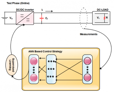
The author has proposed a buck DC-DC converter based on ANN, which is used to control the output voltage of a DC-DC buck converter. It is capable of operating in both no-load and full-load conditions. It is also capable of controlling non-linear DC-DC buck converters. This process has been compared with the conventional PID control of a DC-DC converter. Figure 20 shows the offline DC-DC conversion process using the neural network method, and Figure 21 shows the offline DC-DC conversion process using the ANN method [62-64].
Figure 21. The on-line DC-DC conversion process using ANN
An analysis includes the performance comparison of high-gain converters in the application of PV. The performance analysis of various work is reported in Table 4. In the comparison it is noted that efficiency of the converter is reported but corresponding output and input voltage are not mentioned for the simplification purpose. The comparison of different work is done based on the different parameters such as 1) Efficiency of Worst-case. 2) Active devices quantity, 3) Frequency of switching, 4) Converter data size. Different types of converters are performance are analyzed. High step-up ratios efficiently were not delivered by the boost converters due to loss of diode reverse recovery, voltage stress, and high switching current. The converter topologies such non-isolated are best solution since it connected to the side of high output voltage. The voltage difference between high voltage (DC link) and low voltage (FC link) is high and between two electrical circuits electrical solution is required. In FC power generation converters of push pull are unsuitable due to the transformer saturation. The rectifier diode suffers from voltage stress from the modified fly-back converters. In a discontinuous mode current, operates in single winding carries, utilization of poor core, and has high off-state voltage. The study [65] shows the requirements of the voltage clamping circuits to minimize the switch stress. The greater number of switches are required in the active clamp circuit and causes the conduction losses because of triangular current waveforms formation. The converter efficiency measured in provides the high efficiency plotted in Figure 22 for the conventional boost converter. The maximum efficiency of 92.6% is obtained for 40 V to 380V DC-DC conversion and Figure 23 shows the comparison analysis of DC-DC converter topology with respect to high voltage gain.
Table 4. Comparison of DC-DC converter topology with respect to high voltage gain
|
Topology |
Power Rating in W |
Input Voltage (Vin) |
Output Voltage (V) |
No. Active Devices |
Switching Frequency (kHz) |
Transformer Turns Ratio |
Switching |
|
Flyback |
350 |
27 |
410 |
3 |
110 |
5.65 |
Soft |
|
350 |
27 |
410 |
2 |
110 |
4.57 |
Hard |
|
|
Coupled inductor |
210 |
25 |
370 |
3 |
110 |
5.65 |
ZVS |
|
1100 |
41 |
385 |
3 |
55 |
2.65 |
ZCS |
|
|
320 |
28 |
410 |
2 |
110 |
1.25 |
ZCS |
|
|
210 |
26 |
210 |
3 |
70 |
22 |
Soft |
|
|
260 |
32 |
410 |
3 |
25 |
2 |
Hard |
|
|
Non-Isolated Interleaved |
410 |
28 |
410 |
3 |
45 |
2 |
Soft |
|
1100 |
45 |
410 |
3 |
55 |
2.12 |
Soft |
|
|
1100 |
50 |
390 |
3 |
110 |
2 |
Soft |
|
|
Push Pull |
1100 |
28 |
390 |
3 |
110 |
2 |
Soft |
|
1510 |
32 |
360 |
3 |
110 |
2 |
Soft |
|
|
Half bridge |
1100 |
25 |
410 |
4 |
350 |
1.233 |
Hard |
|
1250 |
35 |
400 |
5 |
55 |
1.65 |
Soft |
|
|
250 |
30 |
360 |
5 |
110 |
1.452 |
Soft |
|
|
1100 |
35 |
420 |
5 |
55 |
5.322 |
ZVS |
|
|
1100 |
24 |
250 |
5 |
110 |
4.266 |
Hard |
|
|
1520 |
30 |
300 |
7 |
110 |
1.2555 |
ZVS |
|
|
Full bridge |
510 |
32 |
360 |
6 |
110 |
1.33 |
Soft |
|
1300 |
33 |
610 |
5 |
65 |
1.65 |
Hard |
|
|
1100 |
25 |
1100 |
5 |
110 |
1.89 |
Soft |
|
|
1450 |
110 |
410 |
5 |
260 |
1.68 |
ZVS |
|
|
Interleaved isolated |
210 |
32 |
250 |
12 |
110 |
1.65 |
Soft |
|
1210 |
35 |
410 |
9 |
12 |
0.5 |
Hard |
|
|
220 |
12 |
210 |
9 |
110 |
0.25 |
Soft |
Figure 22. Plotted efficiency vs. power
Figure 23. The comparison analysis of DC-DC converter topology with respect to high voltage gain
In this paper, an extensive survey has been carried out on DC-DC boost converter techniques and ANN DC-DC converters, considering efficiency, switching operations, reliability, and stability. The most important parameters considered for this survey are voltage gain and voltage stress factor when connected to a solar PV system.
Furthermore, a comprehensive survey has been conducted on non-isolated step-up interleaved and coupled inductors when connected to solar PV system applications, and the findings are outlined. This article discusses stress factors on DC-DC converters. When extensive switching operations are performed on DC-DC converters, stress is mitigated by using a coupled inductor with the ZVS operation system to reduce grid instability as well as synchronization drawbacks.
The significance of every DC-DC converter and ANN DC-DC converter is thoroughly discussed in this review. Connecting the microgrid to a solar PV system significantly enhances the flexibility of the power system using various converter techniques, which are discussed in this work.
This paper presents a discussion on the selection process of a converter linking the PV source and the DC link bus to enhance system performance. Additionally, an extensive analysis has been carried out on bidirectional inverter-switched operated DC-DC converters, which are implemented in a microgrid with a solar PV system to reduce the capacitor voltage stress. This extends further to the impact of ANN converter techniques on DC-DC converters to enhance stability, flexibility, switching operation, stress factor, and reliability issues.
The authors would like to thank JSS Academy of Technical Education, Bengaluru, JSS Science and Technology University, Mysuru, Visvesvaraya Technological University (VTU), Belagavi and Vision Group on Science and Technology (VGST) Karnataka Fund for Infrastructure strengthening in Science & Technology Level-2 sponsored “Establishment of Renewable Smart Grid Laboratory” for all the support and encouragement provided by them to take up this research work and publish this paper.
[1] Narimani, M., Moschopoulos, G. (2014). An investigation on the novel use of high-power three-level converter topologies to improve light-load efficiency in low power DC/DC full-bridge converters. IEEE Transactions on Industrial Electronics, 61(10): 5690-5692. https://doi.org/10.1109/TIE.2014.2300063
[2] Wu, T.F., Chen, Y.K. (1998). Modeling PWM DC/DC converters out of basic converter units. IEEE transactions on Power Electronics, 13(5): 870-881. https://doi.org/10.1109/63.712294
[3] Cha, H., Peng, F.Z., Yoo, D.W. (2010). Distributed impedance network (Z-network) dc–dc converter. IEEE Transactions on Power Electronics, 25(11): 2722-2733. https://doi.org/10.1109/TPEL.2010.2049376
[4] Fang, X., Ding, X., Zhong, S., Tian, Y. (2019). Improved quasi-Y-source DC-DC converter for renewable energy. CPSS transactions on Power Electronics and Applications, 4(2): 163-170. https://doi.org/10.24295/CPSSTPEA.2019.00016
[5] Aranda, E.D., Litrán, S.P., Prieto, M.B.F. (2020). Combination of interleaved single-input multiple-output DC-DC converters. CSEE Journal of Power and Energy Systems, 8(1): 132-142. https://doi.org/10.17775/CSEEJPES.2020.00300
[6] Manjunath, T.N., Mallikarjunaswamy, S., Komala, M., Sharmila, N., Manu, K.S. (2021). An efficient hybrid reconfigurable wind gas turbine power management system using MPPT algorithm. International Journal of Power Electronics and Drive Systems (IJPEDS), 12(4): 2501-2510. https://doi.org/10.11591/ijpeds.v12.i4.pp2501-2510
[7] Kumar, G.G., Krishna, M.S., Kumaravel, S., Babaei, E. (2020). Multi-stage DC-DC converter using active LC2D network with minimum component. IEEE Transactions on Circuits and Systems II: Express Briefs, 68(3): 943-947. https://doi.org/10.1109/TCSII.2020.3021609
[8] Thazeen, S., Mallikarjunaswamy, S., Saqhib, M.N., Sharmila, N. (2022). DOA method with reduced bias and side lobe suppression. In 2022 International Conference on Communication, Computing and Internet of Things (IC3IoT), Chennai, India, pp. 1-6. https://doi.org/10.1109/IC3IOT53935.2022.9767996
[9] Dayananda, P., Srikantaswamy, M., Nagaraju, S., Velluri, R., Kumar, D.M. (2022). Efficient detection of faults and false data injection attacks in smart grid using a reconfigurable Kalman filter. International Journal of Power Electronics and Drive Systems (IJPEDS), 13(4): 2086-2097. https://doi.org/10.11591/ijpeds.v13.i4.pp2086-2097
[10] Mahendra, H.N., Mallikarjunaswamy, S., Subramoniam, S.R. (2023). An assessment of vegetation cover of Mysuru City, Karnataka State, India, using deep convolutional neural networks. Environmental Monitoring and Assessment, 195(4): 526. https://doi.org/10.1007/s10661-023-11140-w
[11] Seol, K.S., Woo, Y.J., Cho, G.H., Gho, G.H., Lee, J.W. (2009). A synchronous multioutput step-up/down DC–DC converter with return current control. IEEE Transactions on Circuits and Systems II: Express Briefs, 56(3): 210-214. https://doi.org/10.1109/TCSII.2009.2015372
[12] Jiang, W., Chincholkar, S.H., Chan, C.Y. (2017). Investigation of a voltage-mode controller for a DC-DC multilevel boost converter. IEEE Transactions on Circuits and Systems II: Express Briefs, 65(7): 908-912. https://doi.org/10.1109/TCSII.2017.2723660
[13] Hui, S.Y., Shrivastava, Y., Sathiakumar, S., Tse, K.K., Chun, H.S.H. (1998). A comparison of nondeterministic and deterministic switching methods for DC-DC power converters. IEEE Transactions on Power Electronics, 13(6): 1046-1055. https://doi.org/10.1109/63.728332
[14] Xiao, H., Xie, S. (2008). A ZVS bidirectional DC–DC converter with phase-shift plus PWM control scheme. IEEE Transactions on Power Electronics, 23(2): 813-823. https://doi.org/10.1109/TPEL.2007.915188
[15] Zhang, F., Du, L., Peng, F.Z., Qian, Z. (2008). A new design method for high-power high-efficiency switched-capacitor DC–DC converters. IEEE Transactions on Power Electronics, 23(2): 832-840. https://doi.org/10.1109/TPEL.2007.915043
[16] Chen, J., Ngo, K.D. (2001). Alternate forms of the PWM switch model in discontinuous conduction mode [DC-DC converters]. IEEE Transactions on Aerospace and Electronic Systems, 37(2): 754-758. https://doi.org/10.1109/7.937489
[17] Ayachit, A., Kazimierczuk, M.K. (2018). Averaged small-signal model of PWM DC-DC converters in CCM including switching power loss. IEEE Transactions on Circuits and Systems II: Express Briefs, 66(2): 262-266. https://doi.org/10.1109/TCSII.2018.2848623
[18] Deng, F., Chen, Z. (2012). Control of improved full-bridge three-level DC/DC converter for wind turbines in a DC grid. IEEE Transactions on Power Electronics, 28(1): 314-324. https://doi.org/10.1109/TPEL.2012.2198835
[19] Ardi, H., Ajami, A. (2018). Study on a high voltage gain SEPIC-based DC–DC converter with continuous input current for sustainable energy applications. IEEE Transactions on Power Electronics, 33(12): 10403-10409. https://doi.org/10.1109/TPEL.2018.2811123
[20] Mallikarjunaswamy, S., Nataraj, K.R., Rekha, K.R. (2014). Design of high-speed reconfigurable coprocessor for next-generation communication platform. In Emerging Research in Electronics, Computer Science and Technology: Proceedings of International Conference, ICERECT 2012, pp. 57-67. Springer India. https://doi.org/10.1007/978-81-322-1157-0_7
[21] Kim, S.Y., Nam, K., Song, H.S., Kim, H.G. (2008). Fault diagnosis of a ZVS DC–DC converter based on DC-link current pulse shapes. IEEE Transactions on Industrial Electronics, 55(3): 1491-1494. https://doi.org/10.1109/TIE.2007.910627
[22] Wang, C.M. (2006). Novel zero-voltage-transition PWM DC-DC converters. IEEE Transactions on Industrial Electronics, 53(1): 254-262. https://doi.org/10.1109/TIE.2005.862253
[23] Kim, K., Cha, H., Park, S., Lee, I.O. (2017). A modified series-capacitor high conversion ratio DC–DC converter eliminating start-up voltage stress problem. IEEE Transactions on Power Electronics, 33(1): 8-12., https://doi.org/10.1109/TPEL.2017.2705705
[24] Shrivastava, Y., Hui, S.Y., Sathiakumar, S., Chung, H.S. H., Tse, K.K. (2000). Harmonic analysis of nondeterministic switching methods for DC-DC power converters. IEEE Transactions on Circuits and Systems I: Fundamental Theory and Applications, 47(6): 868-884. https://doi.org/10.1109/81.852940
[25] Alafnan, H. (2024). Sustainable cities: The Economic feasibility of 50% renewable energy production for the city of Ha'il in Saudi Arabia. In 2024 IEEE 8th Energy Conference (ENERGYCON), Doha, Qatar, pp. 1-6. https://doi.org/10.1109/ENERGYCON58629.2024.10488791
[26] Pavithra, G.S., Pooja, S., Rekha, V., Mahendra, H.N., Sharmila, N., Mallikarjunaswamy, S. (2023). Comprehensive analysis on vehicle-to-vehicle communication using intelligent transportation system. In International Conference on Soft Computing for Security Applications, pp. 893-906. Singapore: Springer Nature Singapore. https://doi.org/10.1007/978-981-99-3608-3_62
[27] Mahendra, H.N., Mallikarjunaswamy, S., Kumar, D.M., Kumari, S., Kashyap, S., Fulwani, S., Chatterjee, A. (2023). Assessment and prediction of air quality level using ARIMA model: A case study of Surat City, Gujarat State, India. Nature Environment & Pollution Technology, 22(1): 199-210. https://doi.org/10.46488/NEPT.2023.v22i01.018.
[28] Umashankar, M.L., Mallikarjunaswamy, S., Sharmila, N., Kumar, D.M., Nataraj, K.R. (2023). A survey on IoT protocol in real-time applications and its architectures. In ICDSMLA 2021: Proceedings of the 3rd International Conference on Data Science, Machine Learning and Applications, pp. 119-130. Singapore: Springer Nature Singapore. https://doi.org/10.1007/978-981-19-5936-3_12
[29] Mahendra, H.N., Mallikarjunaswamy, S., Subramoniam, S.R. (2023). An assessment of built-up cover using geospatial techniques–a case study on Mysuru District, Karnataka State, India. International Journal of Environmental Technology and Management, 26(3-5): 173-188. https://doi.org/10.1504/IJETM.2023.130787.
[30] Pooja, S., Mallikarjunaswamy, M., Sharmila, S. (2023). Image region driven prior selection for image deblurring. Multimedia Tools and Applications, 82: 24181-24202. https://doi.org/10.1007/s11042-023-14335-y
[31] Rathod, S., Ramaswamy, N.K., Srikantaswamy, M., Ramaswamy, R.K. (2022). An efficient reconfigurable peak cancellation model for peak to average power ratio reduction in orthogonal frequency division multiplexing communication system. International Journal of Electrical and Computer Engineering, 12(6): 6239-6247. http://doi.org/10.11591/ijece.v12i6.pp6239-6247
[32] Mallikarjunaswamy, S., Basavaraju, N.M., Sharmila, N., Mahendra, H.N., Pooja, S., Deepak, B.L. (2022). An efficient big data gathering in wireless sensor network using reconfigurable node distribution algorithm. In 2022 Fourth International Conference on Cognitive Computing and Information Processing (CCIP), Bengaluru, India, pp. 1-6. http://doi.org/10.1109/CCIP57447.2022.10058620
[33] Mahendra, H.N., Mallikarjunaswamy, S. (2022). An efficient classification of hyperspectral remotely sensed data using support vector machine. International Journal of Electronics and Telecommunications, 68(3): 609-617. http://doi.org/10.24425/ijet.2022.141280
[34] Shivaji, R., Nataraj, K.R., Mallikarjunaswamy, S., Rekha, K.R. (2022). Implementation of an effective hybrid partial transmit sequence model for peak to average power ratio in MIMO OFDM system. In ICDSMLA 2020: Proceedings of the 2nd International Conference on Data Science, Machine Learning and Applications, pp. 1343-1353. Springer Singapore. https://doi.org/10.1007/978-981-16-3690-5_129
[35] Savitha, A.C., Jayaram, M.N. (2022). Development of energy efficient and secure routing protocol for M2M communication. International Journal of Performability Engineering, 18(6): 426-433. https://doi.org/10.23940/ijpe.22.06.p5.426-433
[36] Venkatesh, D.Y., Mallikarjunaiah, K., Srikantaswamy, M. (2022). A comprehensive review of low density parity check encoder techniques. Ingénierie des Systèmes d’Information, 27(1): 11-20. https://doi.org/10.18280/isi.270102
[37] Thazeen, S., Mallikarjunaswamy, S., Saqhib, M.N. (2022). Septennial adaptive beamforming algorithm. In 2022 International Conference on Smart Information Systems and Technologies (SIST), Nur-Sultan, Kazakhstan, pp. 1-4. https://doi.org/10.1109/SIST54437.2022.9945753
[38] Mahendra, H.N., Mallikarjunaswamy, S., Basavaraju, N.M., Poojary, P.M., Gowda, P.S., Mukunda, M., Navya, B., Pushpalatha, V. (2022). Deep learning models for inventory of agriculture crops and yield production using satellite images. In 2022 IEEE 2nd Mysore Sub Section International Conference (MysuruCon), Mysuru, India, pp. 1-7. https://doi.org/10.1109/MysuruCon55714.2022.9972523
[39] Mahendra, H.N., Mallikarjunaswamy, S., Nooli, C.B., Hrishikesh, M., Kruthik, N., Vakkalanka, H.M. (2022). Cloud based centralized smart cart and contactless billing system. In 2022 7th International Conference on Communication and Electronics Systems (ICCES), Coimbatore, India, pp. 820-826. https://doi.org/10.1109/ICCES54183.2022.9835856
[40] Mallikarjunaswamy, S., Sharmila, N., Siddesh, G.K., Nataraj, K.R., Komala, M. (2022). A novel architecture for cluster based false data injection attack detection and location identification in smart grid. In Advances in Thermofluids and Renewable Energy: Select Proceedings of TFRE 2020, pp. 599-611. Springer Singapore. https://doi.org/10.1007/978-981-16-3497-0_48
[41] Thazeen, S., Mallikarjunaswamy, S., Siddesh, G.K., Sharmila, N. (2021). Conventional and subspace algorithms for mobile source detection and radiation formation. Traitement du Signal, 38(1): 135-145. https://doi.org/10.18280/ts.380114
[42] Satish, P., Srikantaswamy, M., Ramaswamy, N.K. (2020). A comprehensive review of blind deconvolution techniques for image deblurring. Traitement du Signal, 37(3): 527-539. https://doi.org/10.18280/ts.370321
[43] Umashankar, M.L., Ramakrishna, M.V., Mallikarjunaswamy, S. (2019). Design of high speed reconfigurable deployment intelligent genetic algorithm in maximum coverage wireless sensor network. In 2019 International Conference on Data Science and Communication (IconDSC), Bangalore, India, pp. 1-6. https://doi.org/10.1109/IconDSC.2019.8816930
[44] Mahendra, H.N., Mallikarjunaswamy, S., Rekha, V., Puspalatha, V., Sharmila, N. (2019). Performance analysis of different classifier for remote sensing application. International Journal of Engineering and Advanced Technology, 9(1): 7153-7158. https://doi.org/10.35940/ijeat.A1879.109119
[45] Thazeen, S., Mallikarjunaswamy, S. (2023). The effectiveness of 6T beamformer algorithm in smart antenna systems for convergence analysis. IIUM Engineering Journal, 24(2): 100-116. https://doi.org/10.31436/iiumej.v24i2.2730
[46] Lakshmi, M., Hemamalini, S. (2017). Nonisolated high gain DC–DC converter for DC microgrids. IEEE Transactions on Industrial Electronics, 65(2): 1205-1212. https://doi.org/10.1109/TIE.2017.2733463
[47] Lakshminarasamma, N., Ramanarayanan, V. (2007). A family of auxiliary switch ZVS-PWM DC–DC converters with coupled inductor. IEEE Transactions on Power Electronics, 22(5): 2008-2017. https://doi.org/10.1109/TPEL.2007.904225
[48] Liu, F., Ruan, X., Jiang, Y. (2022). Resonant peak suppression approaches for improving the dynamic performance of DCX-LLC resonant converter based two-stage DC–DC converter. IEEE Transactions on Industrial Electronics, 70(6): 5685-5695. https://doi.org/10.1109/TIE.2022.3192604
[49] Sharma, R., Gao, H. (2006). Low cost high efficiency DC-DC converter for fuel cell powered auxiliary power unit of a heavy vehicle. IEEE Transactions on Power Electronics, 21(3): 587-591. https://doi.org/10.1109/TPEL.2006.872380
[50] Gamand, F., Li, M.D., Gaquière, C. (2012). A 10-MHz GaN HEMT DC/DC boost converter for power amplifier applications. IEEE Transactions on Circuits and Systems II: Express Briefs, 59(11): 776-779. https://doi.org/10.1109/TCSII.2012.2228397
[51] Cao, X., Chiang, W.J., King, Y.C., Lee, Y.K. (2007). Electromagnetic energy harvesting circuit with feedforward and feedback DC–DC PWM boost converter for vibration power generator system. IEEE Transactions on Power Electronics, 22(2): 679-685. https://doi.org/10.1109/TPEL.2006.890009
[52] Ma, D., Zhang, C. (2006). Thermal compensation method for CMOS digital integrated circuits using temperature-adaptive DC–DC converter. IEEE Transactions on Circuits and Systems II: Express Briefs, 53(11): 1284-1288. https://doi.org/10.1109/TCSII.2006.882346
[53] Kwak, B.C., Hong, S.K., Kwon, O.K. (2018). A highly power-efficient single-inductor bipolar-output DC–DC converter using hysteretic skipping control for OLED-on-silicon microdisplays. IEEE Transactions on Circuits and Systems II: Express Briefs, 65(12): 2017-2021. https://doi.org/10.1109/TCSII.2018.2815994
[54] Pandey, S.K., Patil, S.L., Chaskar, U.M., Phadke, S.B. (2018). State and disturbance observer-based integral sliding mode controlled boost DC–DC converters. IEEE Transactions on Circuits and Systems II: Express Briefs, 66(9): 1567-1571. https://doi.org/10.1109/TCSII.2018.2888570
[55] Su, F., Ki, W.H. (2008). Component-efficient multiphase switched-capacitor DC–DC converter with configurable conversion ratios for LCD driver applications. IEEE transactions on circuits and systems II: Express Briefs, 55(8): 753-757. https://doi.org/10.1109/TCSII.2008.922467
[56] Ambusaidi, K., Pickert, V., Zahawi, B. (2009). New circuit topology for fault tolerant H-bridge DC–DC converter. IEEE Transactions on Power Electronics, 25(6): 1509-1516. https://doi.org/10.1109/TPEL.2009.2038217
[57] Banaei, M.R., Bonab, H.A.F. (2016). A novel structure for single-switch nonisolated transformerless buck–boost DC–DC converter. IEEE Transactions on Industrial Electronics, 64(1): 198-205., https://doi.org/10.1109/TIE.2016.2608321
[58] Labibah, Y., Sasmono, S., Romdlony, M.Z., Syafrianto, D., Hakim, A., Hariyanto, N. (2024). The stability solution for 100% variable renewable energy supply in microgrid through batteries energy storage system: Case study the iconic Island Nusa Penida. In 2024 IEEE 4th International Conference in Power Engineering Applications (ICPEA), Pulau Pinang, Malaysia, pp. 209-213. https://doi.org/10.1109/ICPEA60617.2024.10498776
[59] Bae, H., Lee, J., Yang, J., Cho, B.H. (2008). Digital resistive current (DRC) control for the parallel interleaved DC–DC converters. IEEE Transactions on Power Electronics, 23(5): 2465-2476. https://doi.org/10.1109/TPEL.2008.2002059
[60] Núñez, R.O., Oggier, G.G., Botterón, F., Garcia, G.O. (2016). Analysis of the transformer influence on a three-phase dual active bridge DC-DC converter. IEEE Latin America Transactions, 14(7): 3048-3055. https://doi.org/10.1109/TLA.2016.7587601
[61] Ofoli, A.R., Rubaai, A. (2006). Real-time implementation of a fuzzy logic controller for switch-mode power-stage DC–DC converters. IEEE Transactions on Industry Applications, 42(6): 1367-1374. https://doi.org/10.1109/TIA.2006.882669
[62] Habibi, M.R., Baghaee, H.R., Dragičević, T., Blaabjerg, F. (2020). False data injection cyber-attacks mitigation in parallel DC/DC converters based on artificial neural networks. IEEE Transactions on Circuits and Systems II: Express Briefs, 68(2): 717-721. https://doi.org/10.1109/TCSII.2020.3011324
[63] Rojas-Dueñas, G., Riba, J.R., Moreno-Eguilaz, M. (2021). Black-box modeling of DC–DC converters based on wavelet convolutional neural networks. IEEE Transactions on Instrumentation and Measurement, 70: 1-9. https://doi.org/10.1109/TIM.2021.3098377
[64] Jiang, Y., Xia, L., Zhang, J. (2021). A fault feature extraction method for DC–DC converters based on automatic hyperparameter-optimized 1-D convolution and long short-term memory neural networks. IEEE Journal of Emerging and Selected Topics in Power Electronics, 10(4): 4703-4714. https://doi.org/10.1109/JESTPE.2021.3131706.
[65] Kumar, A., Sood, Y.R., Maheshwari, A. (2024). Power systems resilience enhancement through renewable energy integration: Insights and future directions. In 2024 IEEE 4th International Conference in Power Engineering Applications (ICPEA), Pulau Pinang, Malaysia, pp. 140-145. https://doi.org/10.1109/ICPEA60617.2024.10498721