Ahmed Yahya Qasim![]() | Fadhil R. Tahir
| Fadhil R. Tahir![]() | Ahmed Nasser B. Alsammak*
| Ahmed Nasser B. Alsammak*![]()
© 2024 The authors. This article is published by IIETA and is licensed under the CC BY 4.0 license (http://creativecommons.org/licenses/by/4.0/).
OPEN ACCESS
Enhancing power quality (PQ) using the Unified Power Quality Conditioner (UPQC) is the focus of this article's research review. There has been a dramatic increase in the use of non-linear and electronically switched devices in distribution lines and industries, which makes PQ issues important. Distribution Flexible AC Transmission Systems (DFACTSs) are a novel idea developed to improve the performance of the distribution system. One of the DFACTSs is the UPQC. The design of this UPQC aims to resolve various PQ problems, such as voltage sag/swell, single-phase and three-phase failures, voltage flicker, compensation of current/voltage harmonics, reactive power demand of the load, and compensation of unbalanced loads. It is possible to build the UPQC to protect sensitive loads that are located inside the distribution system and to prevent any distortion from coming from the load side. This study presents a comprehensive analysis of the different configurations of UPQC systems for single-phase and three-phase applications. The UPQC is categorized based on factors such as voltage sag compensation, supply system, converter topology, and system configuration. According to its function, topology, and application, many researchers have given the UPQC several various names, like Multi-Converter UPQC (UPQC-MC), Interlined UPQC (UPQC-I), Distributed Generator UPQC (UPQC-DG), Right Shunt UPQC (UPQC-R), etc. This study is meant to provide a detailed overview of the many possible UPQC system formations.
UPQC, harmonic compensation, active power filter, power quality, D-FACTSs
PQ issues are gaining attention and have become a big problem for users of energy [1]. The distribution system is facing increasing issues in terms of voltage sag/swell and harmonics production. These challenges are a result of the growing use of nonlinear loads, such as modern power electronics and computer-controlled equipment [2]. These issues can potentially damage delicate equipment and cause costly losses for electrical networks [3]. Poor power quality causes electrical equipment to malfunction and causes loads to behave abnormally. Harmonic current and more reactive power demand are caused by several electronic devices, which generate unbalanced loads and fluctuating voltages [4]. These problems can be solved in part via LC passive filters. However, this filter type is unable to address the issue of unpredictable fluctuations in the load voltage and source current waveforms. To ensure conformance with power quality regulations, various forms of active power filters (APFs) are now widely utilized [5].
Technology known as custom power developed to assist power distribution systems mitigate various PQ issues. Distribution systems utilize custom power devices (or D-FACTSs) to enhance the quality and reliability of power supplies [6]. The Dynamic Voltage Restorer (DVR), the Distribution Static Compensator (D-STATCOM), and the UPQC are the three primary devices of the compensatory type custom power [7]. Voltage sag/swell, voltage fluctuations, and other situations in which the load's power supply is interrupted are the main functions of DVR [8], while a nonlinear load's harmonic and unbalanced current are compensated by the D-STATCOM [9]. The UPQC is a hybrid device that combines the functionalities of a D-STATCOM and a DVR. It is classified as an element of the Active Power Filter family. Installing the UPQC at the power distribution networks' Point of Common Coupling (PCC) can improve PQ [10].
The UPQC system, designed by Fujita and Akagi in 1998, to improve PQ at both the source and load ends [11]. Since then, a large number of researchers have worked on this device. These researches are separated into four major groups according to the physical composition of the UPQC, techniques utilized to compensate for sag/swell in the source voltage, different UPQC control systems, and various algorithms for determining the best location of the UPQC. This UPQC's physical structure, including its supply system, converters, and UPQC configurations, determines its classification. The UPQC system may be divided into four primary types, including UPQC-Q, UPQC-P, UPQC-S, and UPQC-VAmin, based on the voltage compensating technique.
This paper is divided into eight sections. The basics of UPQC arrangement are covered in Section 2. The control objectives are provided in Section 3. The UPQC classifications are shown in Section 4. Techniques for series APF voltage compensation are provided in Section 5. Various UPQC control methods were covered in Section 6. The optimum location of UPQC for the distribution system was discussed in Section 7. Section 8 provides the study's conclusions.
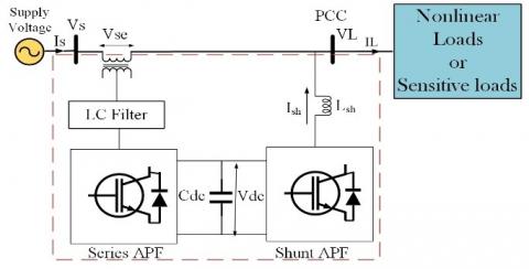
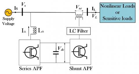
FACTS devices have been popular as a PQ issue solution in recent years [12]. A new generation of compensating devices has been created as a consequence of the FACTS concepts being used in distribution systems [13]. A UPQC's primary purpose is to compensate the PQ issues of source voltage like sags, swells, imbalance, harmonics, and flickers, as well as load current PQ issues like harmonics, reactive current, unbalance and neutral current. The UPQC can enhance PQ at the PCC in power distribution and industrial power systems [14]. Both series and shunt APFs make up a UPQC. Thus, it can compensate for voltage and current in a synchronized manner. A UPQC's series APF manages voltage-related problems across the load such as to the DVR, while the UPQC's shunt APF compensates load-related current issues, like to the D-STATCOM. The UPQC has many advantages for enhancing PQ. It can handle voltage and current-related PQ issues and filter harmonics, reducing the need for multiple devices in the distribution network. The UPQC offers active compensation for current distortion and correction of power factor, which decreases load supply-voltage fluctuations. The voltage can be controlled by UPQC for both grid and load sides. The UPQC mitigates voltage and current distortions simultaneously and independently, resulting in sinusoidal source current and load voltage at the desired voltage level [15]. Figure 1 illustrates a simplified version of the UPQC system configuration. The primary parts of UPQC are as follows [10]:
Figure 1. UPQC schematic
The series injection transformer links the series converter across the network.
UPQC combines two converters shunt and series working as APFs with common dc capacitor. A shunt APF can inject reactive current to correct the power factor, inject harmonic current to address load current harmonics and balance supply currents via injecting negative and zero-sequence components as required by the load. It can also control the DC bus voltage. A series APF regulates the voltages at the load bus by injecting negative and zero sequence voltages to compensate for those in the source, controls the magnitude of the load voltage by injecting the active power components that are necessary, and isolates the load bus from harmonics in the source voltages by injecting harmonic voltages [16].
The UPQC is suitable for both low and medium voltage applications. According to its physical structure, this UPQC is typically divided into three assemblies as follows [17]:
Below is an explanation of the UPQC classifications that were above mentioned.
4.1 Classification based on the supply system
Depending on the type of supply system, UPQC categorization into two groups: single-phase and 3-phase. There are three subtypes of a 3-phase system and single-phase systems: three-phase three-wire (3ph3w), three-phase four-wire (3ph4w), and single-phase two-wire (1ph2w). The issues with voltage harmonics in power quality are the same in 3-phase and single-phase systems. However, a system with three phases must address voltage unbalance. In the 3ph3w system, the current imbalance is taken into account. Additionally, neutral current compensation is required [18]. The single-phase system has problems with reactive current of the load and current harmonics. The 1ph2w supply is made up of two H-bridge inverters, and the UPQC system's architecture is designed to compensate for PQ issues (total eight switches) [19]. Utilizing transformers in single-phase UPQCs increases system size compared to conventional configurations since these transformers are normally bigger to accommodate the whole load current. As a result, the single-phase UPQC that uses a transformer is more complicated, expensive, loses more power, and may limit the power density of the inverter [20].
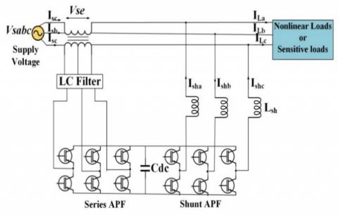
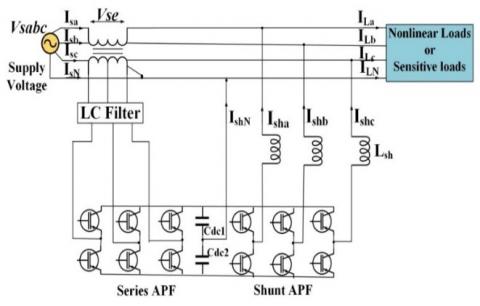
The 1ph2w UPQC architecture based on VSI was introduced in the study [21]. In Figure 2, a 3ph3w VSI-based UPQC is shown. It is the most studied UPQC system configuration [22]. Several factories use a 3-phase, four-wire power source to supply power to a wide range of single-phase and 3-phase equipment. The neutral conductor, which is the fourth wire, produces an excessive flow of neutral current and needs further compensation. The two split capacitor depicted in Figure 3 is only one of many alternative shunt APF designs [23].
Figure 2. 3Ph3W UPQC architecture
Figure 3. 3Ph4W UPQC based on two capacitor shunt converter architecture
4.2 Classification based on converter
A UPQC uses the same DC link for its series and shunt converters. The shunt inverter's main function is maintaining a constant reference voltage for the self-supporting DC connection. Inverter topologies can consist of either a voltage source inverter (VSI) or a current source inverter (CSI). The VSI is regulated using PWM and employs a shared energy storage capacitor (Cdc) to create the DC-link. Figure 1 illustrates the UPQC using VSI and associated devices. VSI topology offers many advantages compared to CSI, including lower weight, flexible overall control, reduced cost, and the ability to operate at multiple levels [24].
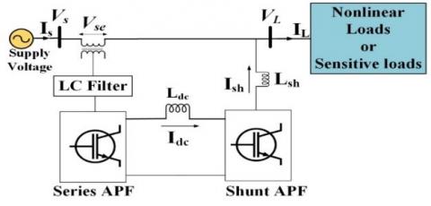
The second UPQC topology consists of PWM CSI that shares an inductor (Ldc). Figure 4 illustrates the UPQC based on the current source inverter. The UPQC controls the DC current so that the power losses are zero and the average output power is equal to the average input power [25]. The main reason the CSI topology is not popular in UPQC is the higher conduction losses of the inductors used as energy storage devices [18]. The advantages of VSI include reduced cost, smaller size, less weight, the capacity to perform multilayer operations, and flexible overall control [26].
Figure 4. The UPQC based on CSI
4.3 UPQC categorization based on configuration
This section provides explanations of the various UPQC configurations. One of the configuration-based categories for UPQC is left and right shunt UPQC. The two converters in UPQC are linked in a back-to-back configuration. It may be categorized depending on where the shunt inverter is located in relation to the series inverter. The left shunt UPQC (UPQC-L) is the name of the shunt inverter on the left side of the UPQC, while the right shunt UPQC (UPQC-R) is the name of the shunt inverter on the right side [27]. Figure 5 illustrates the configuration of UPQC-L [28]. Whatever the kind of load current, sinusoidal currents comprise the bulk of currents passing through the series transformer in UPQC-R. With this arrangement, the shunt inverter reduces the current harmonics [9]. The UPQC-R arrangement can operate in a state where it absorbs zero power and maintains a power factor of unity at the load end. UPQC-R provided improved compensation by minimizing the THD of the load voltage and source current compared to UPQC-L. Both the UPQC topologies exhibited equivalent performance in minimizing oscillating reactive power components [27]. The UPQC-R system's configuration is shown in Figures (1 through 3) consequently; UPQC-R provides an optimum overall UPQC performance than UPQC-L.
Figure 5. The configuration of UPQC-L
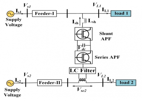
The UPQC Interlined (UPQC-I) arrangement is shown in Figure 6. Jindal et al. [29] proposed this arrangement in (2007). This configuration consists of shunt and series inverters positioned between two distribution feeds. One inverter is connected to one feeder in series, while another is linked to another feeder in shunt. The UPQC-I can regulate and control the real power flow between two feeders. Ravi and Sathish Kumar [30] proposed using the PQ theory to control voltage/current fluctuations and harmonic distortions in multi-feeders Interlined UPQC (MF-IUPQC). Researchers suggested controlling the shunt VSI using the pq theory and the series VSI using the SRF theory. Compared to PI and fuzzy, the MF-IUPQC system performed better after implementing ANFIS. This approach effectively compensates for harmonics and DC-link voltage, ensuring smooth operation, while also providing exact control over the load voltage.
Figure 6. The UPQC-I arrangement
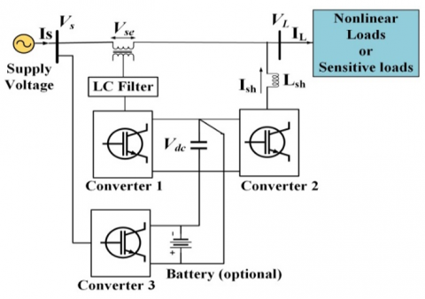
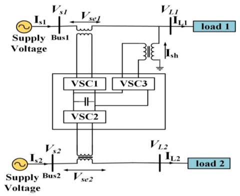
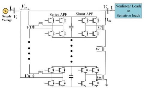
Researchers have investigated whether a UPQC system's performance might be improved using a third converter module for DC bus support that named Multi Converter UPQC (MC-UPQC). Both storage batteries and supercapacitors, which are discussed in the study [31], may be employed to further improve the overall system performance. There are many ways to connect the third inverter, either in parallel with the same feeder or in series with another feeder [32]. Figure 7 depicts the MC-UPQC arrangement. Mohammadi et al. [13] examined an updated MC-UPQC arrangement for a multi-feeder system. The suggested control topologies can completely safeguard essential and sensitive loads in two-feeder distribution systems against abrupt changes in load, voltage sags/swells, and fault interruption. Different control approaches for the MC-UPQC configuration to improve PQ have been discussed in the studies [33, 34]. Figure 8 illustrates the configuration of MC-UPQC for multi feeder system [32].
Muñoz et al. [35] proposed a novel structure known as UPQC Modular (UPQC-MD). This configuration is achieved by linking numerous of H-bridges, i.e., many single-phase UPQCs in cascade. It could be beneficial for increasing power levels. Figure 9 illustrates the UPQC-MD structure. The H-bridges from several series inverters are linked in parallel and fed into the power grid via series transformers, as depicted in the study [35]. Xiao et al. [36] proposed a configuration architecture for medium-voltage systems (10kV 4MVA) that integrates the modular multilevel converter (5 levels) with UPQC. For applications involving medium voltage and large capacity, instead of using a conventional two- or three-level converter, a modular multilevel converter with UPQC can be used to efficiently deal with the varying demands of voltage and current compensations. Long et al. [37] discussed the concept of using the Modular Multilevel Converter on UPQC (13-level MMC-UPQC), which is based on the dq0 transformation for its operation principle and control strategy. Parida and Das [38] used the same design of MMC-UPQC with different control approaches. The fuzzy logical modulation method was proposed by Kenjrawy et al. [39] as a means to enhance the functionality of multilevel parallel-series UPQCs. The higher level (nine-level) is to blame for the lower rate of variation (dv/dt) compared to the lower levels (five-level and seven-level).
Figure 7. The MC-UPQC arrangement
Figure 8. The configuration of MC-UPQC for multi feeder system
Figure 9. The UPQC-MD structure
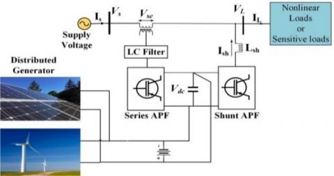
The use of UPQC in integrating renewable resources like solar and wind with the utility system is another expanding area of study in this field [40]. The name of this overall structure is UPQC Distributed Generator (UPQC-DG). The DG sources in this arrangement are linked into a DC connection [41]. The primary advantage of connecting the UPQC-DG's backup power and stored energy batteries to the dc bus is that it eliminates voltage interruptions [42]. Furthermore, there are two modes for distributing the energy produced through the DG. One is the interconnected mode, which powers both the load and the grid. The other is the island mode, which provides power to various loads [43]. Figure 10 displays the structure of the UPQC-DG system [44].
Figure 10. The configuration of the UPQC-DG
Campanhol et al. [45] performed exhaustive assessments of the size, stability, and power flow of the system by employing series and shunt power converters along with a one-stage PV system that was connected to UPQC. The UPQC served as a bidirectional interface when a dispersed generating system was placed between the grid and either general loads or an AC microgrid. The PV-UPQC system has presented power flow examinations, and many mathematical formulas have been developed to characterize the real power of both two inverters [45]. Through employing a PV-B-UPQC combination of a solar photovoltaic array and batteries, Devassy et al. [46] have established a technique for implementing an automatic transition between the autonomous and grid linked operating modes. Moreover, smooth power generation is facilitated by the system, which reduces power fluctuations caused on by weather-related PV power generation.
Jayanti et al. [47] conducted research on the use of UPQC to improve fault ride-through support and VAR assistance for wind-driven FSIG in response to Irish grid requirements. The APF series can provide the required voltage to prevent the FSIG from across the limit of speed in the case of a voltage reduction caused by a grid-side breakdown. Furthermore, the UPQC shunt APF has the capability to provide any necessary extra VAR assistance during the fault [47]. To improve the power quality in distribution networks, Sundarabalan et al. [48] proposed a fuel cell integrated (3ph-4w) Unified Power Quality Conditioner (FCI-UPQC). The fuel cells can provide significant power backing in the event of supply interruptions on the grid side. Their incorporation in this work enhances the effectiveness of the system. In the study [49], an ultracapacitor (UC) and UPQC were suggested for integration with distribution renewable energy generating systems to preserve the MG's power quality. The ultracapacitors' functionality and design were included in the system that was suggested, along with a bidirectional converter that could charge and discharge the UC and the UPQC. The UPQC has performed dynamic voltage restorer (DVR) and APF functions on the MG and load sides, respectively.
The development and design of the wind energy fed UPQC system were presented by Samal and Hota [50]. Enhancing wind energy production and using it to supply the DC link capacitor of the UPQC is the primary objective of the study that is being suggested. This will operate the UPQC for PQ testing and keep the voltage across the capacitor constant. In various balanced and unbalanced load circumstances, the UPQC was employed to mitigate voltage sag and swell. Zanib et al. [51] performed research on the study of power flow and PQ improvement of a system of wind PV power production integrated with UPQC, which are wholly based on the presumed double compensation scheme and different modes of operation. This research is essential for designing inverters properly by taking into account the nonlinear features of the load, the impact of certain current disturbances on grid voltages, and the maximum power generated by the PV and wind power systems. Researchers have suggested many techniques to enhance voltage profiles and mitigate PQ issues in the distribution networks via the use of the UPQC-DG. These methods include using solar arrays and/or wind energy as the basis for the UPQC-DG, as detailed in the studies [52-55].
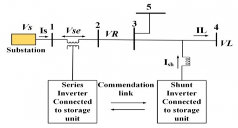
Brenna et al. [56] created an open Unified Power Quality Conditioner (UPQC-O) system with physically isolated series and shunt inverters and no DC connection. To link the supply and the PCC, transformers were used for the series inverter (VSI 1). A smoothing inductance was employed to connect the shunt inverter (VSI 2) in parallel with the PCC [57]. Figure 11 depicted a radial distribution network consisting of 5 buses, with a structure of UPQC-O. Bus 4 contains the UPQC-O's shunt inverter, while the series inverter is close to bus 2 [58]. In the study [59], in response to dynamic load changes in a distribution systems (33-bus and 69-bus), for the purpose of identifying the optimum reactive power set points for UPQC-O, the research suggested an online optimization of the operating technique. A new architecture for a PV fed open-UPQC has been presented by Dash et al. [60], concentrating on the needs of voltage-sensitive loads. The series and shunt inverters of UPQC include adaptive controllers, which have improved the system's ability to withstand various kinds of voltage and current distortions.
Figure 11. An exemplary configuration for a UPQC-O in a 5-bus network
UPQC systems can be classified according to the control strategy used for compensating voltage sags and swells, with each method named depending on its main purpose. The UPQC systems are divided into four types: UPQC-P, UPQC-Q, UPQC-S, and UPQC-VAmin [61]. A comparison of UPQC-P, UPQC-Q, and UPQC-S is shown in Table 1.
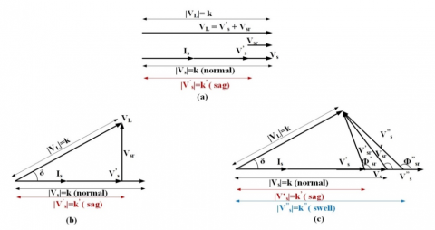
The UPQC-S is a system that utilizes both active and reactive power simultaneously. The series inverter can compensate for both active and reactive power simultaneously, while the shunt APF is utilized for all current-based recompense. Figure 12(c) shows the simultaneous compensating of voltage sag and swell using a series inverter. The compensation is carried out at a predetermined phase angle. This feature of the series inverter improves its efficiency and decreases the VA load on the shunt inverter [41].
Minimum the VA Loading (UPQC-VAmin): for voltage sag compensation, it is needed to reduce the load on the VA. The process involves injecting a series voltage at an appropriate angle in regard to the supply current. When determining the minimum VA loading of UPQC, it is important to consider the current used by the shunt Active Power Filter to ensure the stability of the DC bus and maintain the overall power balance, in addition to the injection of series voltage [61].
Figure 12. Pharos image for voltage sag compensation of (a) UPQC-P, (b) UPQC-Q, (c) UPQC-S [4]
Table 1. A study comparing UPQC-P, UPQC-Q, and UPQC-S
|
UPQC-P |
UPQC-Q |
UPQC-S |
|
Active power is injected or absorbed via a series APF of UPQC to compensate the voltage sag/swell. |
The injection of reactive power is done by a series APF to compensate for voltage sag. |
Active and reactive power are injected or absorbed via a series APF of UPQC to compensate the voltage sag/swell. |
|
The operation of UPQC-P at δ=0. |
The UPQC-Q operates at $\varphi_{s r}$=90. |
The UPQC-S operates at 0<δ<90°. |
|
The shunt inverter only compensates the reactive power. |
The shunt and series inverters provide compensation for reactive power. |
The shunt converter is used with the series converter to compensate the reactive power. |
Many different control methods, algorithms, and approaches that have been successfully applied to UPQC system can be found in the current literature. Methods using frequency domain analysis, such as those employing the fast Fourier transform (FFT), are characterized by their sluggishness and inefficiency, requiring a significant computational burden. As a result, time-domain control algorithms are more favored than frequency-domain control algorithms for real-time control of compensators [64]. Controlling UPQC in the time domain requires immediately generating compensating commands as signals of voltage or current. The dq theory [41] and the pq theory [65] are the most famous time-domain methods. The pq theory is responsible for computing the instantaneous active and reactive powers, while the dq theory deals with current that is independent of source voltage. The DC values include the fundamental component in distorted voltage or distorted current (dq theory), as well as actual and reactive powers connected to the basic components (pq theory) [66]. In both approaches, the current and voltage signals are transferred from the (abc) frame to a reference frame that is either stationary (pq theory) or synchronous (dq theory) to separate the fundamental and harmonic values [67]. The 3-phase pq foundation of the UPQC controller is described in the studies [68, 69], while the UPQC controllers that are grounded on dq theory are covered in the study [70].
Unit vector templates generation (UVTG) is the basis of a simple control method that has been presented in the studies [71, 72]. The technique creates UVTs for single-/three-phase systems using a phase-locked loop, where it’s utilized for extract the fundamental frequency pure sinusoidal signal. This control method creates UPQC's reference signals for both the series and shunt APFs [14].
The power angle control (PAC) of UPQC is an approach that has been suggested to improve the operation of series inverters [73]. The UPQC's PAC shows that the series and shunt inverters can share the reactive power required by the load without raising the UPQC's total rating. This happens by changing the power angle (δ) between the voltages of the load and the supply. As a result, the UPQC shunt inverter's overall rating is decreased [74]. Depending on the method of power angle control, two control strategies may be employed: fixed and variable PAC approaches [75]. The fundamental objective of researchers has been to evaluate the efficacy of PAC control and the whole UPQC system via simulation and experimental approaches [76, 77].
The UPQC was created as a capacitor voltage regulator based on integral plus sliding mode control (SMC) to maintain a constant dc-link voltage with little settling time and no overshoot [78]. The proposed controller enables the capacitor voltage to quickly follow reference values. The series APF of the UPQC was controlled using an SMC approach with a constant frequency scheme [79]. Patjoshi and Mahapatra [80] introduced a method for controlling switching dynamics and a non-linear SMC technique for UPQC. Using SMC and instantaneous active and reactive power. Yavari et al. [81] proposed a method for the UPQC controller. The developed controller had the feature of being stable in the distribution network, despite the loud distortion that was present. Jiang and Zhang [82] created a Modular Multilevel Converter (MMC-UPQC) system to address grid unbalance via a Passive SMC approach. Unbalanced electrical power networks were represented by a mathematical model that was similar to the MMC-UPQC.
The UPQC controller has also been developed using the particle swarm optimization (PSO) approach [83]. To enhance the UPQC's efficiency, a Fractional Order Proportional Integrator (FO-PI) controller is used rather than a traditional PI controller [84]. The integrator's order is fractional, allowing for a further degree of flexibility. For both series and parallel APFs, the controller settings were fine-tuned using Particle Swarm Optimization (PSO).
More recently, a controller based on artificial neural networks (ANNs) has been employed to provide UPQC with its reference signals [85]. Control circuits for PQ devices can benefit from the use of neural networks because of the stability they bring to the converter system and their ability to respond quickly to changing conditions [86]. Multiple inputs multiple outputs systems can be supported by the ANN approach quite well, thus, to address voltage and current issues, the UPQC controller was developed in the studies [87, 88] utilizing the ANN technique.
In current times, the design of controllers employing fuzzy logic is popular. In the studies [89, 90], PI controllers were suggested to address power quality (PQ) issues by using fuzzy controllers with the UPQC. The main objective of the fuzzy controllers is to maintain a consistent voltage in the dc connection. A hybrid UPQC with Distributed Generation has been proposed to mitigate voltage sag and swell. In this regard, a controller based on fuzzy logic control has been developed for the series converter [91]. The installations of the microgrid-based UPQC and Neuro-fuzzy controller have been developed in the study [92]. Two PI and Neuro-Fuzzy controllers were used to physically implement the system. To enhance the PQ of UPQC devices, R. Manivasagam developed four intelligent control strategies. Adaptive neuro-fuzzy interference systems (ANFIS), neuro-fuzzy controllers, fuzzy logic controllers, and ANN controllers were all used to test the performance of the methods [93].
To address the issues of voltage and current harmonics, S. Bharathi et al. proposed the use of a UPQC with a PI controller that is based on Modified Grey Wolf Optimization (MGWO). Additionally, they included renewable energy sources such as a wind turbine squirrel cage induction generator [94]. Nicola et al. [95] developed an efficiency metric for UPQCs and evaluated three different types of controllers: PI-type controllers optimized with Grey Wolf Optimization (GWO), fractional order (FO)-type controllers using integral and differential calculus for fractions, and PI-type controllers used with an RL-TD3 agent.
An appropriate control mechanism is also necessary to produce the pulses the inverter needs. These control methods include hysteresis current control and pulse width modulation (PWM) [74].
Several researchers have investigated UPQC as a method to improve PQ in electrical distribution systems. However, the placement of UPQC in the distribution system must be properly determined because of the significant costs involved. The optimization of UPQC placement can enhance the efficiency of optimal reactive power compensation and involves minimizing power losses, reducing the THD, improving the voltage profile, and reducing imbalance under normal and voltage sag situations. Based on the UPQC size, the optimal location in the radial distribution system can be determined using the differential evolution method [96, 97].
Ganguly [15] proposed integrating the UPQC-PAC model into the forward-backwards sweep load flow algorithm. This integration was used to investigate the effects of UPQC allocation in distribution systems. This analysis used both a 33-bus and a 69-bus test distribution network. Under varying loads and with consideration for static battery charge loads, Saicharan suggested an effective distribution of Distributed Generation (DG) and UPQC in a distribution system, namely the IEEE 33 bus system. The UPQC was put at each bus individually, and various parameters were located and analyzed. The Power Loss Index, the Loss Sensitivity Factor, and the Voltage Stability Index were used to determine which bus was the best choice [7]. Ganguly [98] suggested a multi-objective planning approach based on PSO to address the issue of compensating for reactive power in radial distribution networks using UPQC allocation. This suggested method determines the ideal place to install a UPQC and the optimum amount of reactive power compensation.
In 3-phase unbalanced distribution network, Sarker and Goswami [96] introduced Cuckoo Optimization Algorithm (COA) based (UPQC) allocation. A study evaluated the implementation of UPQC in several scenarios, including a 25-bus radial distribution network and the IEEE 123-node test feeder system. In order to address the issues of (UPQC) placement in radial distribution networks, Ramanaiah and Reddy [99] proposed a new algorithm known as Ant Lion Optimization (ALO). Reducing real power losses and improving the voltage profile are the two main goals of UPQC placement. Standard distribution system (IEEE 69 bus) is used to test the proposed technique. To place open UPQC-O ideally, Lakshmi and Ganguly [100] presented a multi-objective planning technique. Using this method, distribution networks' energy loss can be reduced concurrently with their PV hosting capacity (PVHC). In the suggested technique, the optimized locations to put UPQC-O converters were determined. The suggested PQ improvement approach is based on a hybrid method that combines Grey Wolf Optimization (GWO) and Cuckoo Search Algorithm (CSA). Additionally, the presented approach determines the optimal location of the UPQC device based on the power losses, the cost of UPQC, and Voltage Stability Index. This method is implemented in IEEE (33 and 69 bus), test bus networks [101].
This study is a review on a complete evaluation of the UPQC-based architectures, compensating, control theories, and optimal placement for improving PQ at the distribution networks. The UPQC is a highly efficient device used to address PQ issues related to voltage and current. It effectively resolves problems such as voltage sags and swells, harmonics in voltage and current, voltage and current imbalances, flickers, and reactive power demand. UPQC can be used in several power circuit configurations, each designed to address unique scenarios. In this work, various UPQC configurations are briefly discussed. It is evident from a thorough examination of several control theories that the UPQC's performance is tied to its control techniques; yet, the complexity of the control approach poses a major challenge. The integration of DG with UPQC is the key focus after a comprehensive review of UPQC. By keeping PQ at manageable levels, renewable energy sources like as sun and wind can be used. The optimization approach must be used to select the optimal UPQC placement for a distribution network's bus, taking into account the UPQC rating, voltage stability, and the loss of power of the whole system. This work will be valuable for future researchers that are interested in enhancing power quality using UPQC at the distribution level will find this study to be a useful reference.
The authors express their gratitude to the University of Basrah, namely the College of Engineering and the Electrical Engineering Department, for their valuable help in this study. The authors express gratitude to the University of Mosul, namely the College of Engineering and the Electrical Engineering Department.
|
UPQC |
Unified Power Quality Conditioner |
|
UPQC-L |
Left Shunt UPQC |
|
UPQC-ML |
Multilevel UPQC |
|
UPQC-R |
Right Shunt UPQC |
|
UPQC-Q |
UPQC Reactive Power Control |
|
UPQC-P |
UPQC Active Power Control |
|
UPQC-S |
UPQC Active and Reactive Power Control |
|
MMC-UPQC |
Modular Multilevel Converter on UPQC |
|
PV-UPQC |
Photovoltaic UPQC |
|
UPQC-VAmin |
UPQC Minimum Volt-Ampere |
|
UPQC-O |
Open UPQC |
|
FCI-UPQC |
Fuel Cell Integrated UPQC |
|
UPQC-DG |
Distributed Generation UPQC |
|
MF-IUPQC |
Multi-Feeders Interlined UPQC |
|
THD |
Total Harmonic Distortion |
|
PLL |
The Phased Locked Loop |
|
PCC |
The Point of Common Coupling |
|
APF |
Active Power Filter |
|
VSI |
Voltage Source Inverter |
|
PQ |
Power Quality |
|
UVTG |
Unit Vector Template Generation |
|
SRF |
Synchronous Reference Frame |
|
CSI |
Current Source Inverter |
|
PAC |
Power Angle Control |
|
ANN |
Artificial Neural Network |
|
3Ph4W |
Three-Phase Four-Wires |
|
D-FACTS |
Distribution Flexible AC Transmission System |
|
DVR |
Dynamic Voltage Restorer |
|
ALO |
Ant Lion Optimization |
|
COA |
Cuckoo Optimization Algorithm |
|
GWO |
Grey Wolf Optimizer |
|
LPF |
Low Pass Filter |
|
PSO |
Particle Swarm Optimization |
|
FFT |
Fast Fourier transformer |
|
SMC |
Sliding Mode Control |
|
GWO |
Grey Wolf Optimization |
|
CSA |
Cuckoo Search Algorithm |
|
PVHC |
PV Hosting Capacity |
|
DSTATCOM |
Distribution Static Compensator |
|
ANFIS |
Adaptive-Neuro-Fuzzy-Interference-System |
[1] Al-Hussein, A.B.A., Tahir, F.R., Boubaker, O. (2021). Chaos elimination in power system using synergetic control theory. In 2021 18th International Multi-Conference on Systems, Signals & Devices (SSD), Monastir, Tunisia, pp. 340-345. https://doi.org/10.1109/SSD52085.2021.9429398
[2] Alhattab, A.S., Alsammak, A.N.B., Mohammed, H.A. (2023). An intelligent mitigation of disturbances in electrical power system using distribution static synchronous compensator. Indonesian Journal of Electrical Engineering and Computer Science, 30(2): 633-642. https://doi.org/10.11591/ijeecs.v30.i2.pp633-642
[3] Alsammak, A.N., Mohammed, H.A. (2021). Power quality improvement using fuzzy logic controller based unified power flow controller. Indonesian Journal of Electrical Engineering and Computer Science, 21(1): 1-9. https://doi.org/10.11591/ijeecs.v21.i1.pp1-9
[4] Yadav, S.K., Patel, A., Mathur, H.D. (2020). Comparison of power losses for different control strategies of UPQC. In 2020 IEEE 9th Power India International Conference (PIICON), Sonepat, India, pp. 1-6. https://doi.org/10.1109/PIICON49524.2020.9113005
[5] Alsammak, A.N.B., Al-Kaoaz, H.N.A. (2023). Design of a fuzzy distance relay taking into consideration the impact of using a unified power flow controller. Eastern-European Journal of Enterprise Technologies, 122(5): 6-19. https://doi.org/10.15587/1729-4061.2023.277343
[6] Philip, M.A.D., Kareem, P.F.A. (2020). Power conditioning using DVR under symmetrical and unsymmetrical fault conditions. European Journal of Electrical Engineering, 22(2): 179-191. https://doi.org/10.18280/ejee.220212
[7] Saicharan, K., Gupta, A.R. (2020). Effective placement of UPQC and DG in radial distribution system. In 2020 First IEEE International Conference on Measurement, Instrumentation, Control and Automation (ICMICA), Kurukshetra, India, pp. 1-6. https://doi.org/10.1109/ICMICA48462.2020.9242721
[8] Diwan, A.R., Abdulhasan, K.M. (2019). Proposed topology for voltage sag mitigation with new control strategy. Iraqi Journal of Electrical and Electronic Engineering, 15(2): 138-144. https://doi.org/10.37917/ijeee.16.1.10
[9] Bhosale, S.S., Bhosale, Y.N., Chavan, U.M., Malvekar, S.A. (2018). Power quality improvement by using UPQC: A review. In 2018 International Conference on Control, Power, Communication and Computing Technologies (ICCPCCT), Kannur, India, pp. 375-380. https://doi.org/10.1109/ICCPCCT.2018.8574264
[10] Qasim, A.Y., Tahir, F.R., Alsammak, A.N.B. (2021). Voltage sag, voltage swell and harmonics reduction using Unified Power Quality Conditioner (UPQC) under nonlinear loads. Iraqi Journal for Electrical & Electronic Engineering, 17(2): 140–150. https://doi.org/10.37917/ijeee.17.2.16
[11] Fujita, H., Akagi, H. (1998). The unified power quality conditioner: The integration of series-and shunt-active filters. IEEE Transactions on Power Electronics, 13(2): 315-322. https://doi.org/10.1109/63.662847
[12] AbdElmalek AbdElHafez, A., AL-Sadey, J.I., Al-Bouthigy, R.T. (2013). STATCOM for dynamic performance optimization of grid connected wind power system. Iraqi Journal for Electrical & Electronic Engineering, 9(1): 67.
[13] Mohammadi, H.R., Varjani, A.Y., Mokhtari, H. (2009). Multiconverter unified power-quality conditioning system: MC-UPQC. IEEE Transactions on Power Delivery, 24(3): 1679-1686. https://doi.org/10.1109/TPWRD.2009.2016822
[14] Alhatim, A.Y.Q., Tahir, F.R., Alsammak, A.N.B. (2022). Optimization of power quality using the unified power quality conditioner (UPQC) with unbalanced loads. Al-Rafidain Engineering Journal (AREJ), 27(2): 101-109. https://doi.org/10.33899/rengj.2022.133962.1175
[15] Ganguly, S. (2014). Unified power quality conditioner allocation for reactive power compensation of radial distribution networks. IET Generation, Transmission & Distribution, 8(8): 1418-1429. https://doi.org/10.1049/iet-gtd.2013.0382
[16] Kadam, R., Mulani, K.A., Waghmare, V.B. (2018). Voltage distortion at distribution side reduced by modified UPQC. In 2018 3rd International Conference for Convergence in Technology (I2CT), Pune, India, pp. 1-4. https://doi.org/10.1109/I2CT.2018.8529369
[17] Wanjari, R.A., Savakhande, V.B., Chewale, M.A., Sonawane, P.R., Khobragade, R.M. (2018). A review on UPQC for power quality enhancement in distribution system. In 2018 International Conference on Current Trends Towards Converging Technologies (ICCTCT), Coimbatore, India, pp. 1-7. https://doi.org/10.1109/ICCTCT.2018.8550918
[18] Khadkikar, V. (2011). Enhancing electric power quality using UPQC: A comprehensive overview. IEEE Transactions on Power Electronics, 27(5): 2284-2297. https://doi.org/10.1109/TPEL.2011.2172001
[19] Pal, Y., Swarup, A., Singh, B. (2010). A comparison of single-phase pq theory and UVT based control algorithms for single-phase UPQC. In 2010 Annual IEEE India Conference (INDICON), Kolkata, India, pp. 1-4. https://doi.org/10.1109/INDCON.2010.5712755
[20] Abdalaal, R.M., Ho, C.N.M. (2021). System modeling and stability analysis of single-phase transformerless UPQC integrated input grid voltage regulation. IEEE Journal of Emerging and Selected Topics in Industrial Electronics, 3(3): 670-682. https://doi.org/10.1109/JESTIE.2021.3091395
[21] Meng, L., Ma, L., Zhu, W., Yan, H., Wang, T., Mao, W., Shu, Z. (2021). Control strategy of single-phase UPQC for suppressing the influences of low-frequency DC-link voltage ripple. IEEE Transactions on Power Electronics, 37(2): 2113-2124. https://doi.org/10.1109/TPEL.2021.3106049.
[22] Patel, A., Mathur, H.D., Bhanot, S. (2018). An improved control method for unified power quality conditioner with unbalanced load. International Journal of Electrical Power & Energy Systems, 100: 129-138. https://doi.org/10.1016/j.ijepes.2018.02.035
[23] Zhao, X., Zhang, C., Guo, X., Chai, X., Jia, D., Shi, C., Wei, T. (2020). Novel power flow analysis method based on impedance matching for UPQC with grid voltage fluctuations and unbalanced loads. IET Power Electronics, 13(19): 4417-4427. https://doi.org/10.1049/iet-pel.2019.1447
[24] Pateriya, A., Jain, P. (2021). Topological survey of unified power quality conditioner. International Research Journal of Engineering and Technology, 8(9): 1055-1060.
[25] Melín, P.E., Espinoza, J.R., Baier, C.R., Guzman, J.I., Espinosa, E.E. (2011). Unified power quality conditioner based on current source converters for harmonic mitigation using a decoupled control strategy. In IECON 2011-37th Annual Conference of the IEEE Industrial Electronics Society, Melbourne, VIC, Australia, pp. 4152-4157. https://doi.org/10.1109/IECON.2011.6119992
[26] Vadirajacharya, K., Agarwal, P., Gupta, H.O. (2012). Comparative evaluation of VSI and CSI based unified power quality conditioner. Journal of Electrical and Electronics Engineering, 2(6): 6-13.
[27] Mohammed, B.S., Rao, K.R., Ibrahim, R., Perumal, N. (2012). Performance evaluation of R-UPQC and L-UPQC based on a novel voltage detection algorithm. In 2012 IEEE Symposium on Industrial Electronics and Applications, Bandung, Indonesia, pp. 167-172. https://doi.org/10.1109/ISIEA.2012.6496621
[28] Patnaik, N., Panda, A.K. (2016). Performance analysis of a 3 phase 4 wire UPQC system based on PAC based SRF controller with real time digital simulation. International Journal of Electrical Power & Energy Systems, 74: 212-221. https://doi.org/10.1016/j.ijepes.2015.07.027
[29] Jindal, A.K., Ghosh, A., Joshi, A. (2006). Interline unified power quality conditioner. IEEE Transactions on Power Delivery, 22(1): 364-372. https://doi.org/10.1109/TPWRD.2006.881581
[30] Ravi, T., Sathish Kumar, K. (2022). Analysis, monitoring, and mitigation of power quality disturbances in a distributed generation system. Frontiers in Energy Research, 10: 989474. https://doi.org/10.3389/fenrg.2022.989474
[31] Li, P., Bai, Q., Li, G. (2006). Coordinated control strategy for UPQC and its verification. In 2006 IEEE Power Engineering Society General Meeting, Montreal, Que. p. 8. https://doi.org/10.1109/PES.2006.1709439
[32] Pappula, S.K., Malaji, S. (2018). Harmonic mitigation in multi feeder using multi converter-unified power quality conditioning system. In 2018 8th IEEE India International Conference on Power Electronics (IICPE), Jaipur, India, pp. 1-6. https://doi.org/10.1109/IICPE.2018.8709615
[33] Mukassir, S.M., Mudassir, S.M.M., Sultana, S., Giribabu, D. (2017). The new trend in power conditioning using multi-converter unified power-quality conditioning (MC-UPQC) for multi feeder system. In 2017 International Conference on Energy, Communication, Data Analytics and Soft Computing (ICECDS), Chennai, India, pp. 3356-3361. https://doi.org/10.1109/ICECDS.2017.8390081
[34] Chaudhary, P., Singh, G. (2020). Fault mitigation through multi converter UPQC with hysteresis controller in grid connected wind system. Journal of Ambient Intelligence and Humanized Computing, 11: 5279-5295. https://doi.org/10.1007/s12652-020-01855-w
[35] Muñoz, J.A., Espinoza, J.R., Espinosa, E.E., Baier, C.R., Melín, P.E. (2010). Design of a discrete-time linear control scheme for a modular UPQC. In 2010 IEEE International Symposium on Industrial Electronics, Bari, Italy, pp. 2563-2568. https://doi.org/10.1109/ISIE.2010.5637590
[36] Xiao, X., Lu, J., Yuan, C., Yang, Y. (2013). A 10kV 4MVA unified power quality conditioner based on modular multilevel inverter. In 2013 International Electric Machines & Drives Conference, Chicago, IL, USA, pp. 1352-1357. https://doi.org/10.1109/IEMDC.2013.6556312
[37] Long, Y., Xiao, X., Xu, Y., Yu, B., Xu, Y., Hao, J. (2013). MMC-UPQC: Application of modular multilevel converter on unified power quality conditioner. In 2013 IEEE Power & Energy Society General Meeting, Vancouver, BC, Canada, pp. 1-5. https://doi.org/10.1109/PESMG.2013.6672613
[38] Parida, N., Das, A. (2016). An improved circuit topology of modular multilevel converter (MMC) for DC to AC applications. In 2016 IEEE International Conference on Power Electronics, Drives and Energy Systems (PEDES), Trivandrum, India, pp. 1-6. https://doi.org/10.1109/PEDES.2016.7914294
[39] Kenjrawy, H., Makdisie, C., Houssamo, I., Mohammed, N. (2022). New modulation technique in smart grid interfaced multilevel UPQC-PV controlled via fuzzy logic controller. Electronics, 11(6): 919. https://doi.org/10.3390/electronics11060919
[40] Campanhol, L.B.G., da Silva, S.A.O., de Oliveira, A.A., Bacon, V.D. (2017). Single-stage three-phase grid-tied PV system with universal filtering capability applied to DG systems and AC microgrids. IEEE Transactions on Power Electronics, 32(12): 9131-9142. https://doi.org/10.1109/TPEL.2017.2659381
[41] Devassy, S., Singh, B. (2017). Design and performance analysis of three-phase solar PV integrated UPQC. IEEE Transactions on Industry Applications, 54(1): 73-81. https://doi.org/10.1109/TIA.2017.2754983
[42] Mansor, M.A., Hasan, K., Othman, M.M., Noor, S.Z.B. M., Musirin, I. (2020). Construction and performance investigation of three-phase solar PV and battery energy storage system integrated UPQC. IEEE Access, 8: 103511-103538. https://doi.org/10.1109/ACCESS.2020.2997056
[43] Simatupang, D.P., Choi, J. (2018). PV source inverter with voltage compensation for weak grid based on UPQC configuration. In 2018 IEEE 18th International Power Electronics and Motion Control Conference (PEMC), Budapest, Hungary, pp. 421-427. https://doi.org/10.1109/EPEPEMC.2018.8521943
[44] Wang, J., Sun, K., Wu, H., Zhu, J., Xing, Y., Li, Y. (2020). Hybrid connected unified power quality conditioner integrating distributed generation with reduced power capacity and enhanced conversion efficiency. IEEE Transactions on Industrial Electronics, 68(12): 12340-12352. https://doi.org/10.1109/TIE.2020.3040687
[45] Campanhol, L.B.G., Da Silva, S.A.O., De Oliveira, A.A., Bacon, V.D. (2018). Power flow and stability analyses of a multifunctional distributed generation system integrating a photovoltaic system with unified power quality conditioner. IEEE Transactions on Power Electronics, 34(7): 6241-6256. https://doi.org/10.1109/TPEL.2018.2873503
[46] Devassy, S., Singh, B. (2020). Performance analysis of solar PV array and battery integrated unified power quality conditioner for microgrid systems. IEEE Transactions on Industrial Electronics, 68(5): 4027-4035. https://doi.org/10.1109/TIE.2020.2984439
[47] Jayanti, N.G., Basu, M., Conlon, M.F., Gaughan, K. (2009). Rating requirements of the unified power quality conditioner to integrate the fixed-speed induction generator-type wind generation to the grid. IET Renewable Power Generation, 3(2): 133-143. https://doi.org/10.1049/iet-rpg:20080009
[48] Sundarabalan, C.K., Puttagunta, Y., Vignesh, V. (2019). Fuel cell integrated unified power quality conditioner for voltage and current reparation in four-wire distribution grid. IET Smart Grid, 2(1): 60-68. https://doi.org/10.1049/iet-stg.2018.0148
[49] Kotla, R.W., Yarlagadda, S.R. (2021). Real-time simulations on ultracapacitor based UPQC for the power quality improvement in the microgrid. Journal of New Materials for Electrochemical Systems, 24(3): 166-174.
[50] Samal, S., Hota, P.K. (2018). Wind energy fed UPQC system for power quality improvement. Bulletin of Electrical Engineering and Informatics, 7(3): 495-504. https://doi.org/10.11591/eei.v7i3.945
[51] Zanib, N., Batool, M., Riaz, S., Afzal, F., Munawar, S., Daqqa, I., Saleem, N. (2022). Analysis and power quality improvement in hybrid distributed generation system with utilization of unified power quality conditioner. Computer Modeling in Engineering & Sciences, 134: 1105-1136. https://doi.org/10.32604/cmes.2022.021676
[52] Srilakshmi, K., Srinivas, N., Balachandran, P.K., Reddy, J.G.P., Gaddameedhi, S., Valluri, N., Selvarajan, S. (2022). Design of soccer league optimization based hybrid controller for solar-battery integrated UPQC. IEEE Access, 10: 107116-107136. https://doi.org/10.1109/ACCESS.2022.3211504
[53] Yang, R., Jin, J., Zhou, Q., Mu, S., Abu-Siada, A. (2022). Superconducting magnetic energy storage based DC unified power quality conditioner with advanced dual control for DC-DFIG. Journal of Modern Power Systems and Clean Energy, 10(5): 1385-1400. https://doi.org/10.35833/MPCE.2021.000354
[54] Gongati, P.R.R., Marala, R.R., Malupu, V.K. (2020). Mitigation of certain power quality issues in wind energy conversion system using UPQC and IUPQC devices. European Journal of Electrical Engineering, 22(6): 447-455. https://doi.org/10.18280/ejee.220606
[55] Dahdouh, A., Mazouz, L., Youcefa, B.E. (2022). PIL implementation of feedback linearisation-SVM control of 3-phase multifunctional grid-tied solar PV integrated UPQC. Journal Européen des Systèmes Automatisés, 55(3): 307-322. https://doi.org/10.18280/jesa.550303
[56] Brenna, M., Faranda, R., Tironi, E. (2009). A new proposal for power quality and custom power improvement: OPEN UPQC. IEEE Transactions on Power Delivery, 24(4): 2107-2116. https://doi.org/10.1109/TPWRD.2009.2028791
[57] Kotturu, J., Agarwal, P. (2015). Comparative performance analysis of UPQC and Open UPQC. In 2015 Annual IEEE India Conference (INDICON), New Delhi, India, pp. 1-6. https://doi.org/10.1109/INDICON.2015.7443783
[58] Lakshmi, S., Ganguly, S. (2017). Energy loss minimization with open unified power quality conditioner placement in radial distribution networks using particle swarm optimization. In 2017 7th International Conference on Power Systems (ICPS), Pune, India, pp. 55-60. https://doi.org/10.1109/ICPES.2017.8387268
[59] Lakshmi, S., Ganguly, S. (2019). An on-line operational optimization approach for open unified power quality conditioner for energy loss minimization of distribution networks. IEEE Transactions on Power Systems, 34(6): 4784-4795. https://doi.org/10.1109/TPWRS.2019.2919786
[60] Dash, S.K., Ray, P.K. (2020). A new PV-open-UPQC configuration for voltage sensitive loads utilizing novel adaptive controllers. IEEE Transactions on Industrial Informatics, 17(1): 421-429. https://doi.org/10.1109/TII.2020.2986308
[61] Ambati, B.B., Khadkikar, V. (2014). Optimal sizing of UPQC considering VA loading and maximum utilization of power-electronic converters. IEEE Transactions on Power Delivery, 29(3): 1490-1498. https://doi.org/10.1109/TPWRD.2013.2295857
[62] Qasim, M., Khadkikar, V. (2014). ADALINE based control strategy for three-phase three-wire UPQC system. In 2014 16th International Conference on Harmonics and Quality of Power (ICHQP), Bucharest, Romania, pp. 586-590. https://doi.org/10.1109/ICHQP.2014.6842793
[63] Lee, W.C., Lee, D.M., Lee, T.K. (2009). New control scheme for a unified power-quality compensator-Q with minimum active power injection. IEEE Transactions on Power Delivery, 25(2): 1068-1076. https://doi.org/10.1109/TPWRD.2009.2031556
[64] Singh, B., Chandra, A., Al-Haddad, K. (2014). Power Quality: Problems and Mitigation Techniques. John Wiley & Sons.
[65] Hafez, A.A., Al-Bouthig, R.M., AL-Sadey, J.I. (2015). Unified PQ based STATCOM control for wind driven induction generator. Iraqi Journal for Electrical & Electronic Engineering, 11(1): 10-17. https://doi.org/10.37917/ijeee.11.1.2
[66] Shankar, S., Kumar, A., Gao, W. (2011). Operation of unified power quality conditioner under different situations. In 2011 IEEE Power and Energy Society General Meeting, Detroit, MI, USA, pp. 1-10. https://doi.org/10.1109/PES.2011.6039176
[67] Hembram, M., Tudu, A.K. (2015). Mitigation of power quality problems using unified power quality conditioner (UPQC). In Proceedings of the 2015 Third International Conference on Computer, Communication, Control and Information Technology (C3IT), Hooghly, India, pp. 1-5. https://doi.org/10.1109/C3IT.2015.7060174
[68] Sharma, A., Gupta, N. (2019). GCDSC-PLL and PAC based control of three-phase four-wire UPQC for power quality improvement. In 2019 Fifth International Conference on Electrical Energy Systems (ICEES), Chennai, India, pp. 1-6. https://doi.org/10.1109/ICEES.2019.8719312
[69] Kumar, P. (2020). Power quality investigation by reduced switching UPQC. European Journal of Electrical Engineering, 22(4-5): 335-347. https://doi.org/10.18280/ejee.224-505
[70] Samal, S., Hota, P.K., Barik, P.K. (2020). Performance improvement of a distributed generation system using unified power quality conditioner. Technology and Economics of Smart Grids and Sustainable Energy, 5: 1-16. https://doi.org/10.1007/s40866-020-00095-3
[71] Poongothai, S., Srinath, S. (2020). Power quality enhancement in solar power with grid connected system using UPQC. Microprocessors and Microsystems, 79: 103300. https://doi.org/10.1016/j.micpro.2020.103300
[72] Patel, A.J., Sant, A.V. (2022). EV charging station with cascaded low-pass filtering scheme-based control of unified power quality conditioner. Clean Energy, 6(5): 738-761. https://doi.org/10.1093/ce/zkac052
[73] Khadkikar, V., Chandra, A. (2008). A new control philosophy for a unified power quality conditioner (UPQC) to coordinate load-reactive power demand between shunt and series inverters. International Journal of Advanced Research in Electrical, Electronics and Instrumentation Engineering, 3(8): 11262-11270, https://doi.org/10.15662/ijareeie.2014.0308044
[74] Qasim, A.Y., Tahir, F.R., Alsammak, A.N.B. (2023). Utilizing UPQC-based PAC-SRF techniques to mitigate power quality issues under non-linear and unbalanced loads. Journal Européen des Systèmes Automatisés, 56(5): 823-831, https://doi.org/10.18280/jesa.560513
[75] Khadkikar, V. (2013). Fixed and variable power angle control methods for unified power quality conditioner: Operation, control and impact assessment on shunt and series inverter kVA loadings. IET Power Electronics, 6(7): 1299-1307. https://doi.org/10.1049/iet-pel.2012.0715
[76] Fagundes, S.M., Mezaroba, M. (2016). Reactive power flow control of a dual unified power quality conditioner. In IECON 2016-42nd Annual Conference of the IEEE Industrial Electronics Society, Florence, Italy, pp. 1156-1161. https://doi.org/10.1109/IECON.2016.7793770
[77] Patel, A., Mathur, H.D., Bhanot, S. (2017). A new and simple SRF based power angle control for UPQCdg to integrate solar PV into grid. In 2017 7th International Conference on Power Systems (ICPS), Pune, India, pp. 75-80. https://doi.org/10.1109/ICPES.2017.8387271
[78] Gadgune, S.Y., Waware, M.M. (2014). A novel control strategy for capacitor voltage regulation of Unified Power Quality Conditioner using Integral plus Sliding Mode Controller. In 2014 International Conference on Circuits, Power and Computing Technologies (ICCPCT-2014), Nagercoil, India, pp. 45-52. https://doi.org/10.1109/ICCPCT.2014.7054797
[79] Kolhatkar, Y.Y., Errabelli, R.R., Das, S.P. (2005). A sliding mode controller based optimum UPQC with minimum VA loading. In IEEE Power Engineering Society General Meeting, 2005, San Francisco, CA, USA, pp. 871-875. https://doi.org/10.1109/PES.2005.1489536
[80] Patjoshi, R.K., Mahapatra, K. (2017). High-performance unified power quality conditioner using non-linear sliding mode and new switching dynamics control strategy. IET Power Electronics, 10(8): 863-874. https://doi.org/10.1049/iet-pel.2014.0881
[81] Yavari, M., Edjtahed, S.H., Taher, S.A. (2018). A non-linear controller design for UPQC in distribution systems. Alexandria Engineering Journal, 57(4): 3387-3404. https://doi.org/10.1016/j.aej.2018.02.002
[82] Jiang, C., Zhang, S. (2022). Power quality compensation strategy of MMC-UPQC based on passive sliding mode control. IEEE Access, 11: 3662-3679. https://doi.org/10.1109/ACCESS.2022.3229893
[83] Kumar, G.S., Kumar, B.K., Kumar, M.M. (2010). Optimal VA loading of UPQC during mitigation of unbalanced voltage sags with phase jumps in three-phase four-wire distribution system. In 2010 International Conference on Power System Technology, Zhejiang, China, pp. 1-8. https://doi.org/10.1109/POWERCON.2010.5666492
[84] Nicola, M., Sacerdoțianu, D., Nicola, C.I., Ivanov, S., Ciontu, M., Maria-Cristina, N.I.Ț.U. (2021). Improved control strategy of unified power quality conditioner using fractional order controller and particle swarm optimization. In 2021 International Conference on Applied and Theoretical Electricity (ICATE), Craiova, Romania, pp. 1-6. https://doi.org/10.1109/ICATE49685.2021.9465058
[85] Kota, V.R., Vinnakoti, S. (2017). An artificial neural network based controller for MLC-UPQC with power angle adjustment. In TENCON 2017-2017 IEEE Region 10 Conference, Penang, Malaysia, pp. 250-255. https://doi.org/10.1109/TENCON.2017.8227871
[86] Kinhal, V.G., Agarwal, P., Gupta, H.O. (2010). Performance investigation of neural-network-based unified power-quality conditioner. IEEE Transactions on Power Delivery, 26(1): 431-437. https://doi.org/10.1109/TPWRD.2010.2050706
[87] Mahar, H., Munir, H.M., Soomro, J.B., Akhtar, F., Hussain, R., Elnaggar, M.F., Guerrero, J.M. (2022). Implementation of ANN controller based UPQC integrated with microgrid. Mathematics, 10(12): 1989. https://doi.org/10.3390/math10121989
[88] Zanib, N., Batool, M., Riaz, S., Nawaz, F. (2022). Performance analysis of renewable energy based distributed generation system using ANN TUNED UPQC. IEEE Access, 10: 110034-110049. https://doi.org/10.1109/ACCESS.2022.3213948
[89] Barik, P.K., Shankar, G., Sahoo, P.K. (2020). Power quality assessment of microgrid using fuzzy controller aided modified SRF based designed SAPF. International Transactions on Electrical Energy Systems, 30(4): e12289. https://doi.org/10.1002/2050-7038.12289
[90] Krishna, D., Sasikala, M., Kiranmayi, R. (2022). FOPI and FOFL controller based UPQC for mitigation of power quality problems in distribution power system. Journal of Electrical Engineering & Technology, 17(3): 1543-1554. https://doi.org/10.1007/s42835-022-00996-6
[91] Kumar, K.S., Chatterjee, S., Kumar, P.S., Gatla, R.K., Kumar, A.N. (2023). Mitigation of power quality problems using fuzzy logic-based Unified Power Quality Conditioner (UPQC). Journal Européen des Systèmes Automatisés, 56(2): 195-200. https://doi.org/10.18280/jesa.560203
[92] Renduchintala, U.K., Pang, C. (2016). Neuro-fuzzy based UPQC controller for Power Quality improvement in micro grid system. In 2016 IEEE/PES Transmission and Distribution Conference and Exposition (T&D), Dallas, TX, USA, pp. 1-5. https://doi.org/10.1109/TDC.2016.7519965
[93] Rajendran, M. (2021). Comparison of various control strategies for UPQC to mitigate PQ issues. Journal of The Institution of Engineers (India): Series B, 102(1): 19-29. https://doi.org/10.1007/s40031-020-00502-4
[94] Bharathi, S.L.K., Selvaperumal, S. (2020). MGWO-PI controller for enhanced power flow compensation using unified power quality conditioner in wind turbine squirrel cage induction generator. Microprocessors and Microsystems, 76: 103080. https://doi.org/10.1016/j.micpro.2020.103080
[95] Nicola, M., Nicola, C.I., Sacerdoțianu, D., Vintilă, A. (2023). Comparative performance of UPQC control system based on PI-GWO, fractional order controllers, and reinforcement learning agent. Electronics, 12(3): 494. https://doi.org/10.3390/electronics12030494
[96] Sarker, J., Goswami, S.K. (2016). Optimal location of unified power quality conditioner in distribution system for power quality improvement. International Journal of Electrical Power & Energy Systems, 83: 309-324. https://doi.org/10.1016/j.ijepes.2016.04.007
[97] Taher, S.A., Afsari, S.A. (2012). Optimal location and sizing of UPQC in distribution networks using differential evolution algorithm. Mathematical Problems in Engineering, 2012: 838629. https://doi.org/10.1155/2012/838629
[98] Ganguly, S. (2014). Multi-objective planning for reactive power compensation of radial distribution networks with unified power quality conditioner allocation using particle swarm optimization. IEEE Transactions on Power Systems, 29(4): 1801-1810. https://doi.org/10.1109/TPWRS.2013.2296938
[99] Ramanaiah, M.L., Reddy, M.D. (2017). Optimal placement of unified power quality conditioner using ant lion optimization method. International Journal of Applied Engineering Research, 12(13): 3708-3713.
[100] Lakshmi, S., Ganguly, S. (2018). Simultaneous optimisation of photovoltaic hosting capacity and energy loss of radial distribution networks with open unified power quality conditioner allocation. IET Renewable Power Generation, 12(12): 1382-1389. https://doi.org/10.1049/iet-rpg.2018.5389
[101] Xu, Y. (2020). Hybrid GWO and CS algorithm for UPQC positioning in the power distribution network. JCMPS, 3: 1-9. https://doi.org/10.46253/jcmps.v3i3.a1