Abdel Ilah N. Alshbatat*![]() | Moath Awawdeh
| Moath Awawdeh![]()
© 2024 The authors. This article is published by IIETA and is licensed under the CC BY 4.0 license (http://creativecommons.org/licenses/by/4.0/).
OPEN ACCESS
One of the challenges in Drone-based systems is the limited capacity of the onboard battery. To overcome the limitation of the onboard battery capacity, an intelligent decision-making system for autonomous landing and charging processes is presented in this paper. The system aims to recharge drained battery and extend flight duration. It based on the infrared light-emitting diodes (LEDs) detection and marker recognition. A novel landing pad with twenty infrared LEDs and eight barcodes is carefully designed and used in this research. The landing process is divided into two phases. During the first phase, the LEDs are observed by a camera that is equipped with an infrared-pass filter, while the barcodes are observed by two Pixy cameras in the second phase. To land the Drone on the proper polarity and then start recharging process, a hierarchical vision-based autonomous landing algorithm (HVALA) based on Otsu thresholding method and Laplacian of Gaussian (LOG) operator is proposed. The whole system has been designed and tested through a series of autonomous flights. The experimental results, obtained during the final phase of the landing process confirm the feasibility and robustness of the system where a small error of 4.4cm on average was observed with maximum landing time of 10 seconds. Such error is acceptable in this application and leads to a higher landing success rate.
hexacopter drone, autonomous landing, autonomous charging, marker detection, Otsu method, LOG operator
Drones have the potential to fly over a large area and collect data for multiple applications, such as environmental monitoring, surveillance, waste management, and commercial photography [1]. In addition, Drone can provide solutions that outperform manned systems in terms of mission safety and operational costs. Since Drones are operated by onboard batteries, its range and endurance are limited. To support the continuity of Drone’s missions, there is a need to swap the battery manually or connect the Drone to a power supply for charging station. Such process may limit the efficiency of the system and increases the operation cost. Consequently, there is a need to develop a new technique to land Drones accurately on targeted location and being charged automatically [2].
Currently, Drones are equipped with a Global Position System (GPS) receiver which allows them to reach their destination and go back to their home position safely. Since the accuracy of the GPS is approximately 1-2m, according to several published report by the “Office for Space-Based Positioning, Navigation, and Timing; there is no guarantee that Drone will land exactly at the desired position or at the battery recharging pads. As a result, vision-based technologies have been widely used in Drones for a precise landing on a specific platform [3]. Vision-based technologies can reduce the dependences on the GPS and also reduce the interventions of human operations. Autonomous landing of Drones using the onboard vision-based system requires a robust algorithm to recognize the Conductive Copper Sheet and then calculate Drone’s relative position and distance to the marker. In order to support long-duration flight missions, a well-designed autonomous charging system that enables Drone to charge their battery without human assistance is also essential. Infrared vision-based system has been successfully used for precision landing of Drones [4, 5]. The system requires a downward-facing IR camera, single-board computer, and single IR source. Another technique that combines the visual markers with the infrared technologies is also used for the landing process. Infrared technologies are used to detect the landing position from large distances, while the visual markers are used in the final phase of the landing process. This technique makes the marker visible for any conventional camera and increase the robustness of precision landing. Both technologies can be merged together to form a novel landing platform. Such platform is used to maximize the precision of Drone’s landing process on a dedicated charging platform.
Landing platform that contains an artificial marker are widely used in autonomous landing [6]. Such markers are generally encoded by an inner binary code. This code can be used as a reference point to estimate the onboard camera pose and then the pose of the Drone. The markers can be combined with an IR source and placed either at the center or at the corners of the Landing platform. The IR source emits infra-red beacons for the localization and estimation of the Drone position relative to the platform. In this research, a novel combination of visual barcodes and IR technologies in one landing platform is designed and implemented with a custom-built hexacopter, used to demonstrate the proposed system. Our approach is to place a group of infra-red LEDs lights at the center of the landing platform and surrounding them with several artificial markers. The markers chosen for the design of the landing platform are eight barcodes. The barcodes are attached to eight conductive pads. In order to recognize the conductive copper sheets and guarantee the success of the landing process, two Pixy cameras are also used. Once the system detects all barcodes, control algorithm starts positioning Drone to the proper polarity.
In this paper, we develop an autonomous charging system and upgrade the landing process presented in the study [7]. Consequently, we combine the visual barcodes and infrared technologies in one landing platform. In particular, we integrate the vision-based marker detection and autonomous charging algorithm with the flight control algorithm of the Drone through a hierarchical vision-based autonomous landing algorithm (HVALA). The integrated algorithm can accurately land a Drone and position it over the charging station. The charging system can charge Drone’s battery automatically once the Drones lands on the correct position. The core objective of this research is to develop an autonomous landing and charging system for a Hexacopter Drone. More specifically, this research aims to design a hierarchical vision-based autonomous landing algorithm based on Otsu thresholding method and Laplacian of Gaussian (LOG) operator for precise landing of Hexacopter in outdoor environments.
Generally, the flight duration of a drone can vary widely depending on several factors, including the drone's model, battery capacity, weight, weather conditions, and the type of activities it's engaged in during the flight. Generally, consumer drones can have flight times ranging from as short as a few minutes to around 30 minutes (because of its battery capacity and the weight limit), Drone operator needs to change the battery manually or plug the drone to a power supply for charging, hence developing an autonomous precise landing subsystem for battery recharging is essential, such systems have to be precise and within acceptable time duration mainly in the critical mission. The proposed system in this research contribute to the precision of landing subsystem as well as autonomous charging subsystem which has been achieved by combining more than one technology in one system to strengthen the overall autonomous landing and charging process without affecting the smoothness of landing (i.e more precision can be achieved by increasing the width of conductive copper sheet, at the expense of landing efficiency). Since the focus of this research is to develop a precise autonomous landing system for Drone battery charging, so the efforts in increasing the landing precision considering the design of the drone itself is kept for future work, where a redesigned copper sheet with perforated structure with increased copper width can be investigated under certain design constrains.
The main contributions of this work are: (i) Developing a new precision landing subsystem, and an autonomous charging subsystem using low-cost on-board cameras, and (ii) Design a hierarchical vision-based landing algorithm that detects a group of IR LEDs and a group of visual markers placed on the landing platform. The rest of this paper is organized as follows: Section 2, reviewing the literature in which vision-based systems have been addressed for autonomous landing and charging Drones. In Section 3, an overview of the proposed approach is presented. Section 4 is devoted to the system prerequisites and vision algorithm. In Section 5, we present the system description, where the design of the landing platform including the charging station, the vision system, and Drone are described. In Section 6, we present the experimental results. Remarks, Considerations, and Future Directions are discussed in Section 7. Finally, the conclusions are drawn in Section 8.
At present, several approaches for automating the landing process of a Drone on a landing platform have been studied. A common method is to use vision-based autonomous landing technique for controlling the behaviour of the Drone [8-10]. Patruno et al. [8] present a vision-based system for the pose estimation of the Drone. Their methodology was based on a coarse-to-fine approach to search the target markers. A vision-based system for the position and attitude estimation of the Drone is presented in the study [9], a “Hough transform” used to extract the straight lines in the target images. Those lines are then used with the captured images to estimate the position and attitude of the Drone. The main research groups involved in the development of vision-based autonomous landing systems are reviewed and presented in the study [10], where the details of each algorithm and system is discussed.
In order to recognize the landing platform and assist Drones to land safely, artificial markers (helipad) are widely used. Liu et al. [11] designed a new type of landing pad, which includes several ArUco markers surrounded by a circle. Each marker is composed of a wide black border and an inner binary matrix that defines its identifier. An on-board vision system for autonomous take-off, hovering and landing of MAV is presented in the study [12], the system is based on a single image of a typical landing pad which consists of the letter “H” surrounded by a circle. Design and implementation of a real-time, vision-based landing algorithm for an autonomous helicopter is reported in the study [13], the system is also based on a helipad that consists of the letter “H”. The same mark is used in the study [14]. A visual framework is developed to allow the autonomous landing of a drone on a platform using a single camera. Two methods for automatic detection of landing pads were proposed in the study [15], the landing pads. The landing pads are marked by traditional characters “H” and “X” inside of circles. A custom ArUco marker was proposed in the study [16] which consists of a small marker nested inside a bigger one.
A popular way to achieve a high-precision landing is to use infrared technologies. Gui et al. [17], used four infrared light-emitting diode lamps to positively identify the landing zone. More application of autonomous landing algorithm, that allows the vehicle to land robustly and precisely onto a heaving platform is presented in the study [18], where IR MarkOne beacon and IR Pixy camera were utilized. Hayajneh and Badawi [19], employ the IRLock sensor to track a MarkOne beacon, together with a rangefinder to detect the vertical distance to the landing position. The IRLock sensor is based on the Pixy vision sensor, while the MarkOne beacon is simply an array of infrared LED’s. A precision landing system that consists of an infrared camera and an IR light beam is proposed in the study [20], and a more complex system with an array of 2×72 LEDs, Raspberry Pi, and NoIR camera is presented in the study [21].
Currently, the most common approach is to combine different technologies such as visual markers with infrared technologies. An array of 264 infrared LED and ArUco marker, proposed in the study [22] were used in designing the landing pad. Such design makes the marker visible for a conventional camera even at poor light conditions. Wang and Bai [23] used a square plate as a special landing pad. On the top side of the square plate, an ‘H’ sign is attached at the center and surrounded by 4 red LEDs. These LEDs are used to guide the Drone from long distances. A landing pad consisting of a fractal ArUco marker and a MarkOne beacon is presented in the study [24]. In this research twenty infrared light-emitting diodes and eight barcodes are used to feature a special landing and Conductive Copper Sheet.
In order to increase the endurance and overall flight time of Drones in a real time, several approaches have been proposed to autonomously recharge their batteries during long duration missions. A hot swapping technique is presented in the study [25], such technique is partially autonomous, where Drone is required to fly back to the ground station to replace its battery either manually or automatically. Another technique which is completely autonomous was proposed in the study [26]. Therein, the author presents the automated battery swapping system which includes the design concept of the battery swapping mechanisms and a precise landing technique. Dale [27], describes the design, testing, and construction of an autonomous recharging station for quadrotor using contact-based charging stations. Such method requires a precise landing system and a mechanical system that is able to strongly bond the electrodes for the conductivity.
Autonomous landing and charging systems using onboard vision-based system requires robust algorithms. In order to deal with the control problem of such systems; A number of control algorithms were investigated such as proportional-integral-derivative (PID) [28], model predictive controller [29], and backstepping controller [30]. More advanced controllers were also used such as neural network controller [31], fuzzy logic controllers [32], multi-level fuzzy logic controller [33], and deep reinforcement learning algorithm [34]. Although many control techniques were presented, still designing a high-performance controller for landing and charging Hexacopters is a challenging issue.
In numerous researches focused on achieving precise drone landings, the level of accuracy typically depends on the performance of the camera and the presence of a visible ground marker, vision-based method and development has been widely investigated [35, 36]. Despite the high precision in landing, adaptability, and many advantages of the vision-based autonomous system, still, there are some essential challenges associated with the vision system. such as sensitivity to environmental changes [37], computational complexity, and the quality of cameras system [38]. At the other hand, artificial marker (pads), have also their benefit and challenges, compared to the vision system, Marker-based systems are less sensitive to environmental changes like weather conditions or lighting variations, providing a more robust solution in diverse operational settings, [39]. For adaptability, artificial markers offer less adaptability to dynamic environments or changing conditions compared to vision-based systems, as they depend on fixed markers at predetermined locations, [40]. A combination of both approaches, where feasible, may provide a comprehensive solution that leverages the strengths of each method which is adopted in the research. Moreover, using a combination of visual markers and infrared markers can offer versatility. This approach allows the drone to adapt to changing lighting conditions, and increase the success rate of landing process during different weather conditions. In general, the choice between such systems depends on the specific requirements of the application, the operational environment, and the capabilities of the drone's sensors. Adverse weather conditions, such as strong winds, rain, or fog, can significantly impact drone operations. Winds and rain issues are considered as one of the main operator tasks for setting up a pre-flight planning. The current research addresses the fog issue by combining two techniques while searching the landing area; it mainly focusses on the use of infrared technology. Flying Drone at high altitude presents some unique challenges; such as payload and flight duration. Altitude limits for the current research is limited to 10m, which required a light weight vision system and requires less time to land Drone. On the other hand, any extra wight related to an advanced computer or cameras requires more power which reduces the flight duration.
In this paper, a hierarchical vision-based autonomous landing algorithm (HVALA) based on Otsu thresholding method and LOG operator is proposed. This algorithm combines two approaches to guarantee a successful landing and improving the charging process.
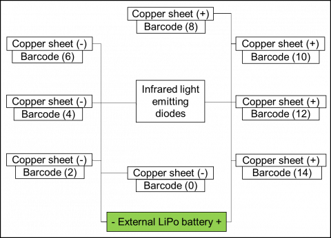
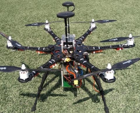
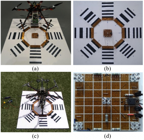
The prototype presented in this research is divided into three subsystems: the landing platform, the vision system, and the Hexacopter Drone. As shown in Figure 1 (a), a novel landing platform with twenty infrared light-emitting diodes (LEDs), eight barcodes, charging structure (eight conductive copper sheets), and power supply is carefully designed and used in this research. The LEDs are arranged in five groups and placed at the center of the landing platform. The barcodes are placed around the LED’s breadboard and attached to the charging system. Figure 1 (b) shows the aerial system which includes the vision system and Hexacopter Drone. The vision system consists of three cameras, two Arduino Nanos, two level shifters, and a Raspberry Pi. Two types of different cameras are used in our system. The main camera is a conventional RGB camera with an IR filter. It used to make sure that the LEDs are detected from high altitudes. The other two cameras are of type Pixy and used to make sure that the barcodes are detected when the Drone is getting close to the conductive copper sheet. In particular, the barcodes are used mainly to align the polarity of the main onboard battery with the charging system. As shown in Figure 1 (c), the system is attached to the bottom of the fuselage. The coordinates of the cameras are aligned with the Drone’s coordinate system so that their attitudes are matched with respect to the landing platform. Figure 1 (d) shows the Hexacopter Drone used in our experiments.
The overall landing and charging strategies are as follows. Drone is required to fly from an initial point to the location of the charging platform using GPS module and then autonomously locate and recognize the landing platform. The location of the landing platform is pre-programmed and defined via five waypoints (WP1, WP2, WP3, WP4, and WP5). Once the main onboard camera detects the regions of the IR-LEDs, Raspberry Pi will command the Pixhawk controller to move Drone towards the centre of the landing platform; denoted by WP5, and descend from there. During this period, Raspberry Pi will extract the center of each region. The center of the four regions at the edge (IR1, IR2, IR3, IR4) are then calculated and compared with the center of IR5. If the difference between them is larger than a certain threshold (In this research, and for the provided experimental study, the threshold is 9 pixel which was driven by several experimental studies. The basis for setting this threshold is the Ground Sampling Distance (GSD), where 1 pixel is corresponding to 0.5cm while Drone is flying at 2m (4.5cm error in landing process equivalent to 9 pixels). More discussion on the pose estimation and control strategy is presented in Sections 4.3 and 4.4 respectively), Raspberry Pi will command the Pixhawk flight controller to change flight mode to position hold and then yaw Drone to north. The previous process will be executed continuously until the result is below the certain threshold. From this point, Drone starts to descend to a lower height slowly. As soon as Drone is above the landing target with 2m, Pixy cameras are activated. Pixy cameras are trained to detect the barcodes and then land Drone at the correct charging plate. In particular, Arduino is programmed to differentiate between the barcodes attached to the positive terminal and to those attached to the negative terminal. After the landing process is completed, Raspberry Pi will initiate the charging mission. In case that the conductive copper sheets are lost, Raspberry Pi will command the Pixhawk flight controller to change flight mode to position hold. During this period, Raspberry Pi will command the Pixhawk flight controller to Yaw Drone and then polls the camera again to check if the conductive copper sheet is detected. If this is the case, the landing procedure continues as usual. Otherwise, Raspberry Pi will command the Pixhawk flight controller to fly Drone back to the first waypoint where it starts another landing attempt from scratch.
In General, ensuring the safety of drone operations during landing and charging is crucial, and various safety measures are typically implemented to address malfunctions or errors. Hence different safety measures can take a place, such as emergency landing protocol, fail-safe mode, sensor redundancy, battery management system, …etc. Various researches investigated the possible risk and safety measures of drone [41-43]. In the event of a malfunction or error, the combination of these safety measures aims to minimize potential risks and ensure the safe operation of the drone system. In this proposal we consider the normal flight scenario and drone operation, taking into account some essential safety measures during the landing and charging process, which are discussed in Section 6, of this paper.
(a) General block diagram for the landing platform
(b) General block diagram for the vision system
(c) Vision system attached to the bottom of the fuselage
(d) Hexacopter used in our experiments
Figure 1. Structure of the proposed approach
4.1 Camera matrix model
To describe the correspondence between a point in the world coordinate system and a point in the two-dimensional image plane, let $\left(X_w, Y_w, Z_w\right)^T$ be the space coordinates of a point $P_w$ in world coordinate system visible to the camera. Meanwhile, let $\left(X_c, Y_c, Z_c\right)^T$ be the image coordinate of the same point $P_C$ in 3D camera coordinate system and $(\tilde{\mathrm{x}}, \tilde{\mathrm{y}})^T$ be the image coordinate of the same point $\tilde{P}_c$ in the twodimensional image plane. Working in homogeneous coordinates, the relationship between a point $P_c$ in the threedimensional camera coordinate system and a point $\tilde{P}_c$ in the two-dimensional image plane using the intrinsic matrix $k$ of a camera can be described in a matrix form as follows:
$\tilde{P}_{\mathrm{c}}=P_o P_c$ (1)
where, $P_o$ is a camera matrix defined as $P_o=k[I \mid 0]$, and the intrinsic matrix $k$ is
$k=\left[\begin{array}{ccc}f_x & 0 & c_x \\ 0 & f_y & c_y \\ 0 & 0 & 1\end{array}\right]$ (2)
Then
$\left[\begin{array}{l}\tilde{\mathrm{x}} \\ \tilde{\mathrm{y}} \\ \tilde{\mathrm{z}}\end{array}\right]=\left[\begin{array}{cccc}f_x & 0 & c_x & 0 \\ 0 & f_y & c_y & 0 \\ 0 & 0 & 1 & 0\end{array}\right]\left[\begin{array}{c}X_c \\ Y_c \\ Z_c \\ 1\end{array}\right]$ (3)
Since the point $P_w$ is located in the world coordinate system, then, an additional transformation is needed to relate the point $P_w$ from the world reference system to the camera reference system. The transformation is accomplished by a rotation matrix $R_{3 \times 3}$ and translation vector $t_{3 \times 1}$ (extrinsic parameters). Therefore, the coordinates of the point $P_c$ given the coordinates of the point $P_w$ can be computed as follows:
$P_c=\left[\begin{array}{cc}R & t \\ 0_{1 \times 3} & 1\end{array}\right] P_w$ (4)
Substituting Eq. (4) in Eq. (1) and then in Eq. (3) will give us the following formulas:
$\begin{aligned} & \tilde{P}_{\mathrm{c}}=P_o P_c \\ & \tilde{P}_{\mathrm{c}}=k[I \mid 0]\left[\begin{array}{cc}R & t \\ 0_{1 \times 3} & 1\end{array}\right] P_w\end{aligned}$ (5)
$\left[\begin{array}{c}\tilde{\mathrm{x}} \\ \tilde{\mathrm{y}} \\ \tilde{\mathrm{z}}\end{array}\right]=\left[\begin{array}{llll}c_{11} & c_{12} & c_{13} & c_{14} \\ c_{21} & c_{22} & c_{23} & c_{24} \\ c_{31} & c_{32} & c_{33} & c_{34}\end{array}\right]\left[\begin{array}{c}X_w \\ Y_w \\ Z_w \\ 1\end{array}\right]$ (6)
The $c$ matrix in Eq. (6) is called complete camera calibration matrix, and the formula is used to map any point $P_w$ in world reference system to the image plane. Accordingly, the exact pixel coordinates of the detected object returned by the camera can be obtained by dividing the first two coordinates of $(\tilde{\mathrm{x}}, \tilde{\mathrm{y}}, \tilde{\mathrm{z}})^T$ by the third coordinate $(u=\tilde{\mathrm{x}} / \tilde{\mathrm{z}}$, $v=\tilde{\mathrm{y}} / \tilde{\mathrm{z}})$ [7].
4.2 Camera calibration
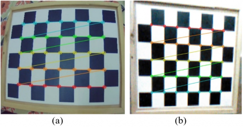
The open-source library OpenCV and classical black-white chessboard are used to estimate the extrinsic and intrinsic camera parameters. In our experimental setup, we calibrated two different cameras: IMX322 and Pixy cameras. We decide to use an 8×6 chessboard as a real-world object for the calibration process. Chessboards are commonly used for camera calibration because they provide a regular pattern of high-contrast features, which facilitates the calibration process. In order to achieve the camera calibration with a balance between having enough calibration points and avoiding unnecessary complexity, we have used am 8×6 chessboard which provides enough points to accurately estimate the intrinsic parameters of the camera. Using a larger chessboard is possible, but that would at the expense of computational complexity, moreover such size choice is very common in the field of computer vision for camera calibration and hence ensure the compatibility across different software tools as well as vision libraries (such as OpenCV, which provides functions specifically designed for detecting corners in an 8×6 chessboard, and it has been used in our experimental studies), although In some cases, especially when dealing with highly specialized applications or specific camera properties, other sizes of chessboards might be chosen for optimal results.
Figure 2 shows a chessboard image with the corners detected for both cameras. We used the OpenCV built-in function cv2.calibrateCamera() to calculate the camera matrix and distortion coefficients. Tables 1, and 2, show our result for both cameras. The camera matrix includes the intrinsic and extrinsic parameters of the camera. The intrinsic parameters of the camera composed of the focal lengths $\left(f_x, f_y\right)$ and the optical center of the camera $\left(c_x, c_y\right)$. Extrinsic parameters $(t, r)$ are related to the translation and rotation vectors, which are used to convert images from camera coordinate system to world coordinate system.
Figure 2. Chessboard image (a) chessboard image with corners detected by IMX322 camera, (b) chessboard image with corners detected by Pixy camera
Table 1. Distortion parameters of the IMX 322, and Pixy camera
|
|
K1 |
K2 |
P1 |
P2 |
K3 |
|
IMX 322 |
-0.4136 |
0.1757 |
-0.0018 |
-0.0055 |
-0.0079 |
|
Pixy |
0.0192 |
0.0778 |
0.0075 |
0.0066 |
-0.2803 |
Table 2. Intrinsic parameters of the IMX322, and Pixy camera
|
|
fx |
fy |
cx |
cy |
|
IMX 322 |
317.67388 |
403.8298 |
327.79963 |
233.78297 |
|
Pixy |
573.41894 |
621.38677 |
371.02411 |
329.16026 |
There are two major kinds of distortion caused by camera Radial distortion causes the straight lines in a real world to be curved when they appeared in the image, while tangential distortion causes the distance between the object and the viewing point to be closer than expected. Distortion coefficients include the radial distortion $\left(k_1, k_2, k_3\right)$ and tangential distortion $\left(p_1, p_2\right)$, in other words, the above five parameters known as distortion coefficient must be found together with above mentioned parameters. Such calibration is essential in our proposed system since the autonomous landing and charging process depends on the correct detection of the landing platform (Barcode, IR, and Conductive Copper Sheet) where the onboard camera is the responsible for detecting the regions of the IR-LEDs. The correct identification of camera parameters, ensure the correct calculation and detection of the landing platform and the center of the four regions at the edge (IR1, IR2, IR3, IR4). Data from the calibration process are obtained and used for the IR-LEDs detection and position estimation presented in subsection 4.3 and 4.4.
4.3 Pose estimation of the drone
As shown in Figure 3, a landing pad with five groups of infrared LEDs are used as a source for Drone pose estimation. In our experimental setup, Otsu's thresholding method is used to determine the infrared LEDs regions in the image. We then apply the Laplacian of Gaussian (LOG) filter to detect the bright blobs in the image. Since there are five bright bobs in the image, we use cv2.findContours() OpenCV built-in function to find the number of contours in the Image and then we calculate the moments for each contour using cv2.moments(). The centroid of each contour is then calculated by the formula $C x=M 10 / M 00$ and $C y=M 01 /$ $M 00$, where $C x$ is the $\mathrm{x}$ coordinate and $C y$ is the y coordinate of the centroid. Meanwhile, M10 is the 1st order spatial moment around x-axis, $M 01$ is the 1 st order spatial moment around y-axis, and $M 00$ is the 0 th order central moment. The centroid of the four regions at the edge (IR1, IR2, IR3, IR4) are then calculated $\left(u_a, v_a\right)$ and compared with the center of IR5 using $\left(\left(u=a b s\left(u_5-u_a\right),\left(v=a b s\left(v_5-v_a\right)\right)\right.\right.$, if the difference is less than a certain threshold, then the four edges will be considered as a searching area and their center will be tracked. The cv2.solvePnP() OpenCV built-in function is used to return the translation and the rotation vectors. The translation and the rotation vectors are then converted to the rotation matrix by the cv2.Rodrigues() OpenCV built-in function, which contains the roll, pitch, and yaw angle of the IR5 marker relative to the camera in the marker's coordinate system. Later, we calculated camera's position and attitude relative to the IR5 marker.
Figure 3. Landing pad with five groups of IR-LEDs
The coordinate system of the camera is aligned with the drone’s coordinate system so that the position and attitude of the camera frame in respect to the IR5 marker is also the position and attitude of the Drone relative to the same marker. The position and attitude of the Drone are then sent to the Pixhawk flight controller so that it can hover directly above the center of the IR5 marker before landing. The landing process is then initiated by activating the Pixy cameras. Pixy cameras are trained to detect the barcodes and then land Drone at the correct charging plate.
4.4 Vision algorithm and control strategy
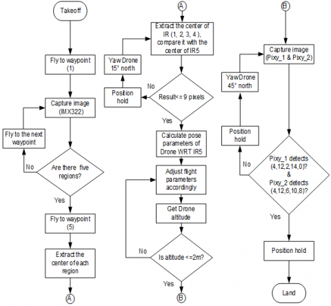
In order to achieve a high-precision landing task, and then initiate the charging process, a hierarchical vision-based autonomous landing algorithm is proposed in this research. The flowchart of our algorithm is presented in Figure 4.
Initially, Drone is required to take-off and fly toward the first waypoint using the GPS module, and then autonomously locate and recognize the candidate regions of the IR-LEDs in the image. If the Raspberry Pi does not detect any bright blobs in the image, it commands the Drone to fly towards the next waypoint and then polls the camera again until it detects five blobs in the image. If this is the case, Raspberry Pi will command the Pixhawk flight controller to fly Drone towards the WP5 and descend from there. During this period, Raspberry Pi will extract the center of each region. The center of the four regions at the edge (IR1, IR2, IR3, IR4) are then calculated and compared with the center of IR5. If the difference between them is larger than nine pixels (such threshold is driven by several experimental studies designed and measured for this purpose. The measures consider the dimension and placement of the conductive sheet on the Drone and ground station. The threshold is determined in order to cover the optimal match of the charging plates as well as the maximum possible placement of the conductive sheet subject to successful charging based on the actual dimension of the designed ground station), Raspberry Pi will command the Pixhawk flight controller to change flight mode to position hold and then Yaw Drone 15 degree toward north.
Figure 4. A flow-chart of the hierarchical vision-based autonomous landing algorithm (HVALA)
The previous process will be executed continuously until the result is below nine pixels. If this is the case, pose parameters of the main camera with respect to the IR5 marker are calculated, and then results will be sent to the Pixhawk flight controller to position Drone above the center of the IR5 marker before landing. During this period, altitude of Drone is calculated. If the result is less than two meters, Pixy cameras are activated. Two Pixy cameras are trained to detect the barcodes and then land Drone at the correct charging plate. The first camera is attached to the Arduino Nano board to look for the barcode values (4, 12, 2, 14, 0), while the second camera is attached to another Arduino Nano board to look for the barcode values (4, 12, 6, 10, 8). If this is not the case, Raspberry Pi will command the Pixhawk flight controller to Yaw Drone 45 degrees and then polls the camera again to check if the barcodes (4, 12) are detected by both cameras. Once this occurs, Raspberry Pi will land Drone and initiate the charging process.
4.5 System pre-requisite considerations and constrains
The proposed system introduces a novel autonomous landing and charging paradigm with combined technologies. Still, as in any other developed system, some constrains and operational parameters contribute to its functionality and effectiveness; such keys are summarized as follows:
4.5.1 Takeoff constrains
Within the used size of landing platform which is relatively small, the drone take off is limited to an altitude of less than 10 meter in order achieve a successful detection of the landing platform. Such constrains can be adjusted upon the variation of the landing platform dimension which is considered for further investigation in future work.
4.5.2 Infrared visibility and barcode detection
Leveraging infrared technology, the visibility of barcodes is constrained to a maximum distance of 2 meters. Beyond this range, the Pixy cameras cease to effectively observe the barcodes. Upon reaching a height of 2 meters above the ground, the Pixy cameras come into play, detecting barcodes.
4.5.3 Normal flight control parameter
The drone adheres to standard flight control parameters, taking into account factors such as wind speed, temperature, and other environmental conditions to ensure stable and controlled flight.
4.5.4 Operation constrains
Operational considerations include a limited flight duration (i.e within the current capability of Drone technology), emphasizing the importance of optimizing energy consumption and flight efficiency. To activate the charging process, a correct alignment of the polarity of conductive copper sheet is required.
The prototype presented in this research is divided into three subsystems: the vision system, the Hexacopter Drone, and the landing platform. The following subsections describe the proposed system in terms of the hardware components used to assemble each subsystem.
5.1 Vision system
The vision system being used in the proposed system is shown in Figure 5. The core components of the system consist of the followings: Raspberry Pi, conventional RGB camera with an IR filter, two Pixy cameras, two Nano Arduinos, and a balancing charging board. Raspberry Pi runs a Python application that processes the output from the cameras according to the proposed algorithm and outputs the pose parameters to the Pixhawk flight controller. Communication between the Raspberry Pi and the Pixhawk is done through the open source MAVLink protocol over a serial connection. All cameras are facing towards the ground. The main camera module is connected to the Raspberry Pi over a USB cable, while the other two cameras are connected to the Arduino Nano boards via a serial to SPI cable.
Figure 5. Vision System (a) Pixy cameras used in the system; (b) RGB camera, Raspberry Pi, and two Nano Arduinos; (c) RGB camera without an IR filter; (d) RGB camera with an IR filter fixed in front of the camera lens. (e) Raspberry Pi assembled with sensor module; (f) Vision system attached to the bottom of the fuselage
Table 3. Technical specifications of the Pixy camera
|
Processor |
NXP LPC4330 |
|
Image sensor |
OV9715, 1280x800 |
|
Lens field-of-view |
75°H, 47°V |
|
Power consumption |
140mA |
|
Power input |
6V to 10V |
|
Data outputs |
UART, SPI, I2C, USB |
|
Dimensions |
38.1×41.91×15.24mm |
|
Weight |
10g |
Table 4. Technical specifications of the IMX323 camera
|
Model |
ELP-USBFHD06H-FV |
|
Image sensor |
IMX323 |
|
Maximum resolution |
1050P |
|
Power consumption |
190mA |
|
Power input |
5V |
|
Data outputs |
USB |
|
Board size |
38×38mm |
|
Weight |
30g |
As shown in Figure 5 (a), two Pixy cameras modules are attached to the board. Pixy camera is a smart vision sensor that can be quickly taught to detect and track objects. It has NXP microcontroller which processes a 640×400 image at a frame rate of 60 frames per second. The camera is designed for object recognition, line tracking, and simple barcode reading. Arduino Nano is programmed in this research to read only eight barcodes. Table 3 shows the technical specifications of the Pixy camera. Figure 5 (b) shows the IMX322 camera. Table 4 shows the technical specifications of IMX322 camera. Figure 5 (c) and (d) show the RGB camera with and without an IR filter. Figure 5 (e) illustrates the assembled system, while Figure 5 (f) shows the vision system attached to the bottom of the fuselage.
5.2 Hexacopter Drone
As shown in Figure 1 (d), a custom-built hexacopter is used to demonstrate the proposed concept and being equipped with a telemetry radio, a GPS receiver, a Pixhawk flight controller, six Electronic Speed Controllers (ESC), six BLDC motors, six (9x4.5) inch propellers, barometer, magnetometer, accelerometer, gyroscope, three cameras, Raspberry Pi, and LiPo battery. Table 5 summarize the name and weight of the main components used to build the system.
As shown in Table 5, the total weight of the main components listed above is approximately 1670g. The total weight of the drone without the payload, including frame, motors, battery, ESC, GPS, radio, cables and other components is around 2063g. Adding the payload to later weight, gives us the total weight of the Drone, which is found to be 2703g. Based on the specification of the used motors, and propellers, and considering the total weight of the drone, the drone’s payload capacity is at 2209g, with a flight time of 17 minutes, which might be extended due to the fact that the actual weight of the payload is 640g which is so small compared to the drone’s payload capacity. Another factor affecting (increased) the flight time is the average ampere draw, which is reduced due to the installation of the vision system components at the center of the Drone, such balance of the vision system component not only reduced the total current but ensure Drone’s stability.
Table 5. The name and weight in grams of the main components
|
Item |
Weight in Grams |
Quantity |
|
S550 Hexacopter Frame |
550g |
1 |
|
Tiger motors (MN2214) |
57g |
6 |
|
6400mAh Lipo Battery |
485g |
1 |
|
Raspberry Pi |
45g |
1 |
|
30amp. ESC |
25g |
6 |
|
Pixhawk |
38g |
1 |
|
Pixy camera |
10g |
2 |
|
IMX323 camera |
30g |
1 |
The telemetry radio operates at 900MHz. It used to send the information from the Pixhawk flight controller to a ground station, such as: battery lifetime, heading, tilt, speed, flight mode, and altitude. Pixhawk flight controller is an advanced autopilot system that features the most advanced processor technology [44], which is able to control the drone based on the received sensor readings. Electronic speed controller provides power to BLDC motors and controls their speed individually using Pulse Width Modulation (PWM) signal. As shown in Figure 6 (a), two conductive pads are placed on the landing gears of the Drone’s front side, which are connected to the P+ and P- pins of the balancing charging board.
5.3 Landing platform
As shown in Figure 6, a novel landing platform is designed with twenty infrared light-emitting diodes, eight barcodes, charging structure, and power supply. The size of the landing platform is 78cm×78cm and consists mainly of two parts: the landing pad, and the wired charging station. As seen in Figure 6 (a), The charging station contains ten conductive copper sheets, eight of them are placed at the charging platform’s surface, and two of them are placed at the end of the Drone’s landing gears. Figure 6 (b) shows the barcodes embedded in the octagon charging station. Moreover, conductive copper sheets with numbers (8, 10, 12, 14) are soldered together and connected to the positive terminal of the external LiPo battery, while sheets with numbers (0, 2, 4, 6) are connected to the negative terminal of the external LiPo battery. Figure 6 (c) shows the landing platform attached to an external LiPo battery.
The onboard LiPo battery is connected to the balancing charging board. The charging plates on the Drone is also connected to the same board. One of the plates is connected to the P+ pin of the balancing charging board, while the second plate is connected to the P- pin of the balancing charging board. In order to match the terminals of conductive copper sheets on Drone with the correct terminals of the charging platform, Arduino Nano is programmed to differentiate between the sheets attached to the positive terminal and to those attached to the negative terminal. The charging process starts once the copper sheets on the charging platform and the copper sheets on the Drone are matched and in contact.
As shown in Figure 6 (d), the main landing pad contains twenty LEDs arranged in five groups and placed at the centre of the charging platform. Each group contains four LEDs that are connected serially. The size of the LED’s breadboard is 9cm×9cm. The board has a voltage regulator and gets its power from an external LiPo battery. Figure 3 shows the five groups where the first, second, third, fourth, and fifth groups are located at (0.5, 0.5), (0.5, 8.5), (8.5, 8.5), (8.5, 0.5), (4.5, 4.5) respectively.
Figure 6. The landing platform with the charging station and LED’s markers (a) Conductive copper sheets attached to the Drone and to the charging station (b) Barcodes embedded in the octagon charging station (c) Wired contact charging station with an external LiPo battery (d) LED’s breadboard used in the landing pad
As discussed earlier, the overarching landing and charging strategies involve a series of autonomous actions. Initially, the drone begin a journey from its starting point to the designated landing platform location, guided by the GPS module. Subsequently, it autonomously undertakes the task of locating and recognizing the landing platform. The specific location of the landing platform is predetermined and outlined through a sequence of five waypoints, namely WP1, WP2, WP3, WP4, and WP5. Upon reaching the searching zone of the landing platform, the main onboard camera comes into play, detecting the regions marked by the IR-LEDs. Following this detection, the Raspberry Pi takes charge, issuing commands to the Pixhawk flight controller. The Pixhawk controller then leads the drone's movement towards the centre of the landing platform, denoted by WP5, initiating a controlled descent from that position. If, during this phase, the presence of conductive copper sheet is confirmed, the landing procedure seamlessly proceeds as usual. However, if the sheets are not detected, the Raspberry Pi intervenes again. It commands the Pixhawk flight controller to navigate the drone back to the first waypoint, initiating a new landing attempt from the initial phase.
This entire operation is designed to be fully autonomous, encompassing flight to the five waypoints via GPS navigation and concluding with the autonomous landing phase facilitated by the main onboard camera. Importantly, this process is crafted to be intervention-free, requiring no manual involvement at any stage of the operation, considering the normal flight control and scenario. For operation under different environmental condition, it worth mentioning that extreme weather condition like strong winds, heavy rain, or intense heat can impact the drone’s electronic systems and flight stability which may lead to malfunction occurrence. High wind for example, can cause drones to drift off or struggle to maintain altitude, while heavy rain can lead to short-circuiting of vital components. Another impact of poor environmental condition, is the visibility; where poor weather condition such as fog, heavy rain, or snow can severly limit the visibility. This is particularly hazardous for visual line-of-sight (VLOS) operations, where the operator must keep the drone within their sight at all time. Pre-flight planning is essential and recommended practice to ensure the safety of the operation. Implementing comprehensive pre-flight weather checks and having contingency plans for adverse weather are the key, this includes monitoring weather forcast and understanding the weather threshold for safety operation of specific drone model. Such considerations have been taken into account while conducting the experimental test for this research, (further safety measures are considered and discussed in next section), as well as the adherence to the airspace regulation in the country to prevent any possible conflicts with other mission. All regulatory compliances measures have been considered before conducting the test and according to the local authority requirement including obtaining the required certificate as well as the authorization for outdoor flight.
As shown in Figures 7, 8, and 9, several experiments have been performed to measure the actual accuracy of the autonomous landing and charging algorithms. In the first set of experiments, the Drone is placed at 8 meters away from the landing platform and then commanded by the Raspberry Pi to take-off to 10m altitude. When Drone reaches the 10m take-off altitude, it flies toward the landing platform based on the GPS module. It autonomously follows a predefined trajectory which is defined via five waypoints (WP1, WP2, WP3, WP4, WP5). Waypoint five indicates the position of the landing platform, while the others represent a horizontal square path surrounding the position of the landing platform that Drone might initially follow. The distance between the waypoints (WP1, WP2, WP3, WP4) is set to 6 meters, while the WP5 is located at the center of the square.
As soon as Drone reaches the first waypoint, it starts the searching process by enabling the onboard vision system. Once the main onboard camera recognizes the landing platform and detects the infrared LEDs, Drone is commanded to move towards WP5 and starts to descend from there slowly. On other hand, if Drone does not detect the infrared LEDs, it will fly to the next waypoint and starts another landing attempt from scratch (i.e flying from any waypoint to WP5 and then start landing). If this is the case after visiting WP4, Raspberry Pi will command the Pixhawk controller to fly the Drone back to the initial point from where it starts another searching attempt from 8m altitude.
In the second set of experiments and during the landing process, a threshold of 2m is set above the position of the landing platform to decide or deny the last phase of the descent process. Pixy system (1) (i.e pixy camera and Arduino) is programmed to detect the barcodes (4, 12, 2, 14, 0), while Pixy system (2) is programmed to detect the barcodes (4, 12, 6, 10, 8) and then land the Drone at the conductive copper sheets. At this step, Raspberry Pi will command the Pixhawk flight controller to change the flight mode to position hold. Position hold is one of the flight modes that pause the descent process and automatically attempts to maintain the current location, heading and altitude of the Drone. During this period, if the polarity of the conductive sheets on Drone does not match the polarity of the charging station, Raspberry Pi will command the Pixhawk controller to Yaw Drone 45 degree until they get matched. Once this process finished, Raspberry Pi will land the Drone and initiate the charging process.
In case that the conductive copper sheet of the ground station are lost, Raspberry Pi will command the Pixhawk controller to fly the Drone back to WP1 from where it starts another landing attempt from scratch. In addition to the aforementioned precautions, specific operational protocols have been established to enhance safety and reliability during the hexacopter's various phases of operation, discussed briefly in Table 6.
Table 6. Main safety measured implemented during the hexacopter's various phases of operation
|
Measure/Action |
Description/Protocol |
|
Take-off Disarm Action (Take-off phase) |
In the event of an unexpected flip during take-off, an automatic disarm action is triggered to swiftly mitigate potential issues and ensure a safe operational start. |
|
Reliable GPS and RTL Mode (Initial phase) |
Ensuring a dependable GPS signal is crucial during the initial flight phase. If, for any reason, the drone encounters GPS signal issues, it is configured to autonomously switch to Return to Launch (RTL) mode, enhancing overall flight stability. |
|
Safe Landing Process Configurations (Landing Phase) |
After the second attempt, specifically during the phase of searching for infrared LEDs from an 8-meter altitude, the flight controller is configured to automatically switch the drone into Landing mode. This proactive measure ensures a controlled response in scenarios where infrared LED detection is challenging Following the second attempt of the final phase of the descent process, especially in situations where the conductive copper sheet are lost, the flight controller is configured to autonomously switch the drone into Landing mode. This feature is designed to address potential challenges in maintaining a stable descent process. |
|
Low Battery Failsafe |
A failsafe mechanism is in place to address low battery scenarios. If the voltage drops below 9.6 volts for a continuous duration of 10 seconds or if the estimated remaining capacity falls below a specified threshold, the flight controller is automatically programmed to switch the drone into Return to Launch (RTL) mode. This ensures a timely response to low battery situations, prioritizing the safe return of the hexacopter. |
These additional measures, spanning take-off, flight initiation, landing configurations, and low battery scenarios, contribute to a comprehensive safety framework, reinforcing the reliability and autonomy of the hexacopter's operational protocols.
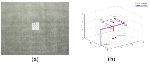
Figure 7 (a) shows an aerial view of the landing platform used in our experiments. The image is taken in flight from the main downward-pointing camera without the IR filter. Figure 7 (b) shows the actual path that is followed by the Drone using the GPS and the main downward-pointing camera with the IR filter. As expected, Drone moved towards WP5 as soon as it reached WP3. This indicates that the landing platform gets in view before reaching WP4. A photo is taken during this period and is shown in Figure 8 (a). From this point, Drone starts to descend to a lower height slowly, Figure 8 (b). After each time that Drone descends, the system checks if the height of the Drone relative to the landing platform is above 2m or not. Once the Drone’s height is below 2m, Figure 8 (c), the Pixy cameras are activated. From this point and onwards, Drone slowly lands automatically on the charging platform, a successful autonomous landing of the Drone is shown in Figure 8 (d). Meanwhile, the position and the attitude of the main onboard camera with respect to the LED’s breadboard is shown in Figure 9. Figure 9 (a) shows an aerial view of the infrared LEDs at an altitude of 8m, while Figures 9 (b), (c), and (d) show three trials while Drone descends on the charging platform. In each experiment, we recorded the landing position of the Drone and measure the distance between the center of the landing pad (IR5) and the center of the main onboard camera. A small error of 4.4cm on average was observed in the landing process. The deviation of up to 4.4cm is deemed acceptable in this application. The drone is programmed to initiate the landing sequence when the error between the center points of IR1, IR2, IR3, and IR4 and the center of IR5 falls below 4.5cm (equivalent to 9 pixels). The LEDs have been strategically placed on a (9×9)cm breadboard, creating a circular arrangement with a radius of 6.36cm. In the charging initiation process, if the drone comes within a distance less than 6.36cm from the central point, it is recognized as a successful condition for triggering the charging process. This error might be solved by increasing the width of the conductive copper sheet, since the width of the conductive copper sheets attached to the drone is 1cm while the width of conductive copper sheet at the landing platform is 5cm. As a result, any error less than 5cm is acceptable for this application. On the other hand, any error larger than 5cm and less than 6.36cm requires to increase the width of the copper sheets attached to the landing platform from 5cm to 7cm, which leads to a higher landing success rate. In addition, the last phase introduces an additional time overhead in the landing process. Trial results are listed in Table 7.
Figure 7. Planned mission, (a) Aerial view of the landing platform without the IR filter, (b) Actual path that is followed by Drone using the GPS and the main downward-pointing camera with the IR filter in one of the tests
Figure 8. Landing flight tests, (a) Drone is hovering over the landing platform at 10m altitude, (b) Drone is hovering over the landing platform at 5m altitude, (c) Drone is hovering over the landing platform at 2m altitude, (d) Drone after landing on the ground platform
Figure 9. LEDs detection and position estimation process, (a) Aerial view of the LEDs at an altitude of 8m, (b) The first trial that indicates the position and the attitude of the camera with respect to the infrared LED’s breadboard, (c) The second trial that indicates the position and the attitude of the camera with respect to the infrared LED’s breadboard, (d) The third trial that indicates the position and the attitude of the camera with respect to the infrared LED’s breadboard
Table 7. The results obtained during the final phase of the landing process using the Pixy cameras
|
Trial |
Landing Error (cm) |
x, y (cm) |
Landing Time (s) |
|
1 |
3.5 |
(6.11, 6.01) |
9 |
|
2 |
5 |
(5.93, 6.07) |
10 |
The proposed autonomous landing and charging system, showcases versatility and potential applicability across various domains such as agricultural drones (performing agricultural tasks over large areas without manual intervention), search and rescue drone (the autonomous landing and charging extend the drone operational range during the critical search and rescue operation), delivery drones (such system can transport packages over short distances and autonomously recharge between delivery, enabling a seamless and efficient delivery process). Drones used for environmental monitoring, such as assessing air quality or tracking wildlife, can benefit from autonomous landing and charging. This feature allows prolonged data collection without manual intervention. Moreover, drones employed for inspecting infrastructure, such as power lines, pipelines, or bridges, can leverage autonomous landing and charging. This capability ensures uninterrupted inspection routines, enhancing the reliability of infrastructure monitoring. The adaptability of such system across various applications demonstrate its potential and open the door for further exploration.
However, system constrains and limitation introduced in Section 4.5, are considered for further investigation. In particular, the altitude of less than 10 meter in order achieve a successful detection of the landing platform, can be managed by increasing the number of IR LEDs as well as increasing the dimension of the landing platform. Another opportunity to improve the proposed system is to increase the drone’s speed during IR detection phase and decreasing the landing time. Such improvement can be partially achieved by replacing the used Raspberry Pi with an advanced companion computer such as Jetson Nano and adding some features to the algorithm to change drone’s speed during the landing process phase. Finally, for future work, and to improve the communication between the companion computer and power supply, the algorithm might be modified, so that, the companion computer will monitor the battery status while charging, and command the drone to take off as soon as the battery is fully charged or as soon as the battery is charged above certain threshold for the case of critical mission. Finally. it should be pointed out, that deploying such autonomous systems bring forth ethical and regulatory considerations that should be taken seriously. One important ethical concern revolves around the preservation of privacy, particularly for such drones equipped with cameras and sensors operating in public spaces. It is very important for regulatory frameworks to address issues related to data collection, storage, and dissemination to ensure compliance with established privacy norms. Safety considerations take precedence, with regulations focusing on collision avoidance systems, adherence to altitude restrictions, and protocols for emergency situations to mitigate the risk of accidents. Ethical considerations extend to fostering public acceptance of autonomous systems through transparency in operations, clear communication about the purpose of drone missions, and addressing public concerns to build trust. Alignment with existing airspace regulations is essential to prevent conflicts with manned aircraft and other airspace users, requiring adherence to no-fly zones, altitude restrictions, and obtaining necessary approvals. Ethical considerations further include minimizing the environmental impact of drone operations, promoting the use of eco-friendly materials, efficient energy consumption, and responsible disposal practices.
Conducting such research on autonomous systems is highly crucial and absolutely essential, at the same time a collaborative approach involving industry stakeholders, policymakers, researchers and the public is indispensable in navigating such ethical and regulatory considerations, facilitating the responsible deployment and integration of autonomous systems into shared or public airspace.
In this research, we have presented the design and implementation of a real-time vision-based autonomous landing and charging system for a Hexacopter Drone. The system aimed to autonomously recharge drained battery and extend the overall flight duration. It based on the infrared LEDs detection and marker recognition. A custom-built hexacopter is used to demonstrate the proposed system and being equipped with a telemetry radio, a GPS receiver, a Pixhawk flight controller, electronic speed controllers, BLDC motors, propellers, barometer, magnetometer, accelerometer, gyroscope, three cameras, Raspberry Pi, balancing charging board, and LiPo battery. A novel landing platform with twenty infrared light-emitting diodes and eight barcodes was carefully designed and used in this research. A hierarchical vision-based autonomous landing algorithm (HVALA) based on Otsu thresholding method and Laplacian of Gaussian (LOG) operator was implemented in this research. The presented algorithm composed of two phases. Both are working sequentially to manage the landing and charging process. During the first phase, the LEDs were observed by the main camera. Algorithm was designed to keep the center of the infrared LED’s breadboard in the center of the image. In the second phase, Once the Drone is 2m above the ground, barcodes were observed by two Pixy cameras. The main strategy of the algorithm in this stage is to align the polarity of the main onboard battery with the charging system and then trigger the charging process. Thereby Drone can continue the mission after being recharged without any external interruption. We demonstrated the feasibility of the proposed algorithm through a series of autonomous flights experiments. The results obtained from the real-time flight experiments have shown that an autonomous landing to within 4.4cm in radius was achieved while introducing an additional time overhead in the landing process.
We gratefully acknowledge the invaluable feedback and suggestions provided by the reviewers, which significantly improved the quality of this work.
[1] Abualigah, L., Diabat, A., Sumari, P., Gandomi, A.H. (2021). Applications, deployments, and integration of internet of drones (IoD): A review. IEEE Sensors Journal, 21(22): 25532-25546. https://doi.org/10.1109/JSEN.2021.3114266
[2] Cocchioni, F., Mancini, A., Longhi, S. (2014). Autonomous navigation, landing and recharge of a quadrotor using artificial vision. In 2014 International Conference on Unmanned Aircraft Systems (ICUAS), IEEE, pp. 418-429. https://doi.org/10.1109/ICUAS.2014.6842282
[3] Lee, H., Jung, S., Shim, D.H. (2016). Vision-based UAV landing on the moving vehicle. In 2016 International Conference on Unmanned Aircraft Systems (ICUAS), Washington, USA, pp. 1-7. https://doi.org/10.1109/ICUAS.2016.7502574
[4] Wenzel, K.E., Rosset, P., Zell, A. (2010). Low-cost visual tracking of a landing place and hovering flight control with a microcontroller. Journal of Intelligent and Robotic Systems, 57: 297-311. https://doi.org/10.1007/s10846-009-9355-5
[5] Wenzel, K.E., Masselli, A., Zell, A. (2011). Automatic take off, tracking and landing of a miniature UAV on a moving carrier vehicle. Journal of Intelligent & Robotic Systems, 61: 221-238. https://doi.org/10.1007/s10846-010-9473-0
[6] Garrido-Jurado, S., Muñoz-Salinas, R., Madrid-Cuevas, F.J., Marín-Jiménez, M.J. (2014). Automatic generation and detection of highly reliable fiducial markers under occlusion. Pattern Recognition, 47(6): 2280-2292. https://doi.org/10.1016/j.patcog.2014.01.005
[7] Alshbatat, A.I.N. (2021). Adaptive vision-based system for landing an autonomous hexacopter drone on a specific landing platform. International Journal of Intelligent Systems Technologies and Applications, 20(3): 245-270. https://doi.org/10.1504/IJISTA.2021.120525
[8] Patruno, C., Nitti, M., Petitti, A., Stella, E., D’Orazio, T. (2019). A vision-based approach for unmanned aerial vehicle landing. Journal of Intelligent & Robotic Systems, 95(2): 645-664. https://doi.org/10.1007/s10846-018-0933-2
[9] Wei, L., Dong, W. J., Yang, L.M. (2017). A vision-based attitude/position estimation for the automatic landing of unmanned helicopter on ship. In Proceedings of the International Conference on Watermarking and Image Processing, pp. 1-5. https://doi.org/10.1145/3150978.3150992
[10] Kong, W., Zhou, D., Zhang, D., Zhang, J. (2014). Vision-based autonomous landing system for unmanned aerial vehicle: A survey. In 2014 International Conference on Multisensor Fusion and Information Integration for Intelligent Systems (MFI), IEEE, pp. 1-8. https://doi.org/10.1109/MFI.2014.6997750
[11] Liu, X., Zhang, S., Tian, J., Liu, L. (2019). An onboard vision-based system for autonomous landing of a low-cost quadrotor on a novel landing pad. Sensors, 19(21): 4703. https://doi.org/10.3390/s19214703
[12] Yang, S., Scherer, S.A., Zell, A. (2013). An onboard monocular vision system for autonomous takeoff, hovering and landing of a micro aerial vehicle. Journal of Intelligent & Robotic Systems, 69: 499-515. https://doi.org/10.1007/s10846-012-9749-7
[13] Saripalli, S., Montgomery, J.F., Sukhatme, G.S. (2003). Visually guided landing of an unmanned aerial vehicle. IEEE Transactions on Robotics and Automation, 19(3): 371-380. https://doi.org/10.1109/TRA.2003.810239
[14] Patruno, C., Nitti, M., Stella, E., D’Orazio, T. (2017). Helipad detection for accurate UAV pose estimation by means of a visual sensor. International Journal of Advanced Robotic Systems, 14(5): 1729881417731083. https://doi.org/10.1177/1729881417731083
[15] De Oliveira, C.S., Anvar, A.P., Anvar, A., Silva Jr, M.C., Neto, A.A., Mozelli, L.A. (2015). Comparison of cascade classifiers for automatic landing pad detection in digital images. In Simposio Brasileiro De Automacao Ineligente.
[16] Wynn, J.S., McLain, T.W. (2019). Visual servoing with feed-forward for precision shipboard landing of an autonomous multirotor. In 2019 American Control Conference (ACC), IEEE, pp. 3928-3935. https://doi.org/10.23919/ACC.2019.8814694
[17] Gui, Y., Guo, P., Zhang, H., Lei, Z., Zhou, X., Du, J., Yu, Q. (2013). Airborne vision-based navigation method for UAV accuracy landing using infrared lamps. Journal of Intelligent & Robotic Systems, 72: 197-218. https://doi.org/10.1007/s10846-013-9819-5
[18] Xuan-Mung, N., Hong, S.K., Nguyen, N.P., Le, T.L. (2020). Autonomous quadcopter precision landing onto a heaving platform: New method and experiment. IEEE Access, 8: 167192-167202. https://doi.org/10.1109/ACCESS.2020.3022881
[19] Hayajneh, M.R., Badawi, A.R.E. (2019). Automatic UAV wireless charging over solar vehicle to enable frequent flight missions. In Proceedings of the 2019 3rd International Conference on Automation, Control and Robots, pp. 44-49. https://doi.org/10.1145/3365265.3365269
[20] Janousek, J., Marcon, P. (2018). Precision landing options in unmanned aerial vehicles. In 2018 International Interdisciplinary PhD Workshop (IIPhDW), IEEE, pp. 58-60. https://doi.org/10.1109/IIPHDW.2018.8388325
[21] Nowak, E., Gupta, K., Najjaran, H. (2017). Development of a plug-and-play infrared landing system for multirotor unmanned aerial vehicles. In 2017 14th Conference on Computer and Robot Vision (CRV), IEEE, pp. 256-260. https://doi.org/10.1109/CRV.2017.23
[22] Wynn, J.S., McLain, T.W. (2019). Visual serving for multirotor precision landing in daylight and after-dark conditions. In 2019 International Conference on Unmanned Aircraft Systems (ICUAS), IEEE, pp. 1242-1248. https://doi.org/10.1109/ICUAS.2019.8798020
[23] Wang, L., Bai, X. (2018). Quadrotor autonomous approaching and landing on a vessel deck. Journal of Intelligent & Robotic Systems, 92: 125-143. https://doi.org/10.1007/s10846-017-0757-5
[24] Badakis, G., Koutsoubelias, M., Lalis, S. (2021). Robust precision landing for autonomous drones combining vision-based and infrared sensors. In 2021 IEEE Sensors Applications Symposium (SAS), pp. 1-6. https://doi.org/10.1109/SAS51076.2021.9530091
[25] Bocewicz, G., Nielsen, P., Banaszak, Z., Thibbotuwawa, A. (2018). Deployment of battery swapping stations for unmanned aerial vehicles subject to cyclic production flow constraints. In Information and Software Technologies: 24th International Conference, ICIST 2018, Vilnius, Lithuania, October 4-6, 2018, Proceedings. Springer International Publishing, 24: 73-87. https://doi.org/10.1007/978-3-319-99972-2_6
[26] Lee, D., Zhou, J., Lin, W.T. (2015). Autonomous battery swapping system for quadcopter. In 2015 International Conference on Unmanned Aircraft Systems (ICUAS), IEEE, pp. 118-124. https://doi.org/10.1109/ICUAS.2015.7152282
[27] Dale, D.R. (2007). Automated ground maintenance and health management for autonomous unmanned aerial vehicles. Doctoral Dissertation, Massachusetts Institute of Technology.
[28] Tan, C.K., Wang, J.L., Paw, Y.C., Liao, F. (2019). Robust linear output feedback controller for autonomous landing of a quadrotor on a ship deck. International Journal of Control, 92(12): 2791-2805. https://doi.org/10.1080/00207179.2018.1459859
[29] Huang, C.M., Chiang, M.L., Hung, T.S. (2017). Visual servoing of a micro quadrotor landing on a ground platform. International Journal of Control, Automation and Systems, 15: 2810-2818. https://doi.org/10.1007/s12555-015-0478-0
[30] Qi, Y., Jiang, J., Wu, J., Wang, J., Wang, C., Shan, J. (2019). Autonomous landing solution of low-cost quadrotor on a moving platform. Robotics and Autonomous Systems, 119: 64-76. https://doi.org/10.1016/j.robot.2019.05.004
[31] Almeshal, A.M., Alenezi, M.R. (2018). A vision-based neural network controller for the autonomous landing of a quadrotor on moving targets. Robotics, 7(4): 71. https://doi.org/10.3390/robotics7040071
[32] Olivares-Mendez, M.A., Kannan, S., Voos, H. (2015). Vision based fuzzy control autonomous landing with UAVs: From V-REP to real experiments. In 2015 23rd Mediterranean Conference on Control and Automation (MED), IEEE, pp. 14-21. https://doi.org/10.1109/MED.2015.7158723
[33] Palafox, P.R., Garzón, M., Valente, J., Roldán, J.J., Barrientos, A. (2019). Robust visual-aided autonomous takeoff, tracking, and landing of a small UAV on a moving landing platform for life-long operation. Applied Sciences, 9(13): 2661. https://doi.org/10.3390/app9132661
[34] Xie, J., Peng, X., Wang, H., Niu, W., Zheng, X. (2020). UAV autonomous tracking and landing based on deep reinforcement learning strategy. Sensors, 20(19): 5630. https://doi.org/10.3390/s20195630
[35] He, Y., Zeng, Z., Li, Z., & Deng, T. (2023, February). A new vision-based method of autonomous landing for UAVs. In 2023 9th International Conference on Electrical Engineering, Control and Robotics (EECR), IEEE, pp. 1-6. https://doi.org/10.1109/EECR56827.2023.10149915
[36] Ortega, L.D., Loyaga, E.S., Cruz, P.J., Lema, H.P., Abad, J., Valencia, E.A. (2023). Low-cost computer-vision-based embedded systems for UAVs. Robotics, 12(6): 145. https://doi.org/10.3390/robotics12060145
[37] Camacho, A.M., Perotto-Baldivieso, H.L., Tanner, E.P., Montemayor, A.L., Gless, W.A., Exum, J., Yamashita, T.J., Foley, A.M., DeYoung, R.W., Nelson, S.D. (2023). The broad scale impact of climate change on planning aerial wildlife surveys with drone-based thermal cameras. Scientific Reports, 13(1): 4455. https://doi.org/10.1038/s41598-023-31150-5
[38] Dhanush, G., Khatri, N., Kumar, S., Shukla, P.K. (2023). A comprehensive review of machine vision systems and artificial intelligence algorithms for the detection and harvesting of agricultural produce. Scientific African, e01798. https://doi.org/10.1016/j.sciaf.2023.e01798
[39] Springer, J., Kyas, M. (2022). Autonomous drone landing with fiducial markers and a gimbal-mounted camera for active tracking. In 2022 Sixth IEEE International Conference on Robotic Computing (IRC), IEEE, pp. 243-247. https://doi.org/10.1109/IRC55401.2022.00047
[40] Xin, L., Tang, Z., Gai, W., Liu, H. (2022). Vision-based autonomous landing for the uav: A review. Aerospace, 9(11): 634. https://doi.org/10.3390/aerospace9110634
[41] Alshbatat, A.I.N., Dong, L., Vial, P.J. (2016). Controlling an unmanned quad-rotor aerial vehicle with model parameter uncertainty and actuator failure. International Journal of Intelligent Systems Technologies and Applications, 15(4): 295-322. https://doi.org/10.1504/IJISTA.2016.080102
[42] Al-Dosari, K., Hunaiti, Z., Balachandran, W. (2023). A review of civilian drones systems, applications, benefits, safety, and security challenges. The Effect of Information Technology on Business and Marketing Intelligence Systems, 793-812. https://doi.org/10.1007/978-3-031-12382-5_43
[43] Ge, Z., Jiang, J., Pugh, E., Marshall, B., Yan, Y., Sun, L. (2023). Vision-based UAV landing with guaranteed reliability in adverse environment. Electronics, 12(4): 967. https://doi.org/10.3390/electronics12040967
[44] Meier, L., Tanskanen, P., Fraundorfer, F., Pollefeys, M. (2011). Pixhawk: A system for autonomous flight using onboard computer vision. In 2011 IEEE International Conference on Robotics and Automation, pp. 2992-2997. https://doi.org/10.1109/ICRA.2011.5980229