Abubakar Siddique![]() | Abdullah Mujahid | Waseem Aslam*
| Abdullah Mujahid | Waseem Aslam*![]() | Muhammad Sajid | Zeeshan Ahmad Arfeen
| Muhammad Sajid | Zeeshan Ahmad Arfeen![]()
© 2024 The authors. This article is published by IIETA and is licensed under the CC BY 4.0 license (http://creativecommons.org/licenses/by/4.0/).
OPEN ACCESS
Voltage-related power quality issues, including voltage sag, swell, and total harmonic distortion (THD), have become a significant concern in recent times. These issues, particularly harmonics, are known to degrade utility performance and lifespan, necessitating urgent rectification to ensure a high-quality power supply. This is crucial as our generation increasingly depends on electricity for enhanced living standards. Flexible AC transmission system (FACTS) devices are gaining considerable interest as effective solutions to these problems. Among these, the dynamic voltage restorer (DVR) is particularly noteworthy for its potential to reduce power quality disturbances in the distribution network. In this study, we developed a DVR based on an artificial neural network (ANN) controller. The activation function employed was Train LM for the input and hidden layers, and pure linear for the output layer, with the Levenberg Marquardt back propagation (LMBP) serving as the training algorithm. The designed model was then tested to tackle voltage-related power quality problems in the distribution network of Jamal Din Wala (JDW) sugar mills. The comprehensive model featured a three-phase voltage source inverter, a scheme utilizing rotating reference frame theory, and sine pulse width modulation (SPWM) for voltage sag and swell sensing along with insulated gate bipolar transistor (IGBT) switching. We analyzed three types of DVR output defects using MATLAB/Simulink and compared the results of the ANN controller with those of a conventional PI controller. The DVR output was modeled in MATLAB/Simulink for three types of defects and two degrees of voltage sag and swell. The results demonstrated that the DVR effectively mitigated voltage sags and swells in the JDW sugar mills distribution network. Furthermore, during the validation of the proposed ANN, a comparison of results with the conventional PI controller under balanced and unbalanced sags and swells showed a significant improvement. The ANN achieved a voltage restoration of up to 99.8% and a total harmonic distortion of 13.5%, a marked improvement over the PI controller, which achieved 97% voltage restoration and 19.5% total harmonic distortion, respectively.
voltage sag swell, distribution feeder, FACTS devices, DVR, PI controller, neural network
JDW sugar mills Punjab, Pakistan have Cogeneration bio mass bagasse fuel-based power plant. JDW sugar mills Cogeneration Power plant is consist of one steam turbine & High-pressure Solid fuel Boiler, having generating power capacity of 26.35MW. JDW power plant is providing power to NEPRA through 132kV grid station and also providing power to JDW sugar mills through 11KV feeder. Most of the time it observed voltages fluctuation at sugar mills 11kV feeder due to inductive load & variation in Grid frequency. Almost all connected load of JDW sugar mills is very sensitive therefore it is planned to lessen the load voltage fluctuation and voltage sage/swell Power quality issues are becoming more prevalent as new electric power delivery infrastructure becomes more electronic [1]. Today's load equipment is more adaptable than older devices. Output losses, economic losses, and environmental consequences [2] can result from poor power quality. The delivery system's most critical and frequent power quality issues are sags, swells, and harmonics. CPDs are used in power systems to address power quality issues. Used to maintain power factor, Circuit voltage and compensate the reactive power. CPDs can adjust power quality (PQ). The DVR can compensate for skewed source voltage by compensating the load voltage [3]. The most recent solution uses neural networks and genetic algorithms in power conditioning devices [4, 5]. Based on biological nervous systems, neural networks have several components that work together. The relationship between elements usually defines the network function. PQ enhancement is achieved using an ANN-controlled DVR [6]. To address low PQ and boost utility efficiency, electric power is analyzed [7-9]. Poor PQ difficulties finally lead to network economic failure. For the electrical utility and end users, PQ is concerned mostly with retaining voltage and current profiles [10].
1.1 Power quality issues
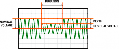
Voltage sag is defined as a 10-90 percent drop in voltage level over a half cycle to one minute. Voltage sag & swell can last a long time equipment life, resulting in an "under-voltage" profile. Instantaneous, momentary, and transient voltage sags exist [9]. Voltage sag during fault condition is shown in Figure 1.
Figure 1. Voltage sag during fault condition
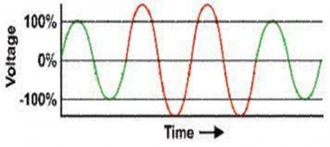
Voltage swell is described as 10-80% of typical switching frequency across a half-cycle to a minute. Over-voltage is a hardware failure. Voltage swell is classified as follows.
When a large load is disconnected, system voltage will rise, Voltage increases when a single line to ground or line to line fault happens. Overheating electronic components and devices can cause voltage swell/ sag as shown in Figure 2.
Figure 2. Voltage swells during fault condition
Electrical machinery is more affected by PQ issues. Voltage sag/swell is a serious problem that power system network is currently experiencing. If not addressed properly, normal concern can increase into a serious problem, resulting in total equipment failure. A situation like this can be solved by starting a new line of custom products. A DVR is one of the most practical ways for protecting against voltage sag/swell [11-14]. To keep the voltage profile consistent, this modified device is coupled in series with the load bus. As a result, it is normally in standby mode. Three single phase transformers that combine the expand and contract operations can be controlled. These voltages are all in phase with the load voltage. DVRs come in three service options [15]: Short circuits and excessive inrush currents are isolated via bypass settings. Current is supplied in a number of variant directions [16].
Voltage sags are quite common in modern power systems and generally caused by Motor starting, Pulsed load switching [16].
Causes of voltage swells include electrical faults, switching operations grid disturbances, such as sudden changes in load or generation and unbalanced faults [16].
1.2 Conventional solutions
Existing solutions to overcome voltage relevant PQ problems include.
1) Capacitor banks
Which has the following disadvantages;
Sensitive to voltage fluctuations;
Have shorter life (8–10 years);
High repairing cost.
2) Synchronous condensers
Disadvantages:
High maintenance cost;
There are considerable losses in the motor;
Except in sizes above 500 kVAR, the cost is greater.
As a synchronous motor has no self-starting torque, therefore, an auxiliary equipment has to be provided for this purpose.
FACTS devices are also available equipped with conventional PI controllers. So, there is always requirement of efficient control strategy having robust and fast response. The proposed solution utilizes neural networks for fast response and efficient performance.
Consider at normal condition (no fault), current through load A and load B is equal (balance load). When there’s fault on feeder 1, a high current (short circuit current) will flow to feeder 1. So, based on Kirchhoff’s Law, currents flow to feeder 2 will be reduced. Consequently, the voltage will also drop in feeder 2. This voltage drop will be defined as voltage sags. Assume Load A=ZLOAD_A, Load B=ZLOAD_B, Feeder 1 Reactance=x1, Feeder 2 Reactance=x2, Current from supply source = I, Current in feeder 1=I1, Current in feeder 2=I2, Total Current in feeders (A+B) I=I1+I2
In normal conditions (without fault in the system),
$I=\frac{V_2}{x_2+Z_{\text {LOUD_B }} B}+\frac{V_2}{x_1+Z_{\text {LOAD }} A}$
When a fault happened in feeder 1, because of short circuit, a high current will flow through feeder 1 as well as source current I. During this time, voltage in feeder 2 decreased due to increasing of voltage drop across source reactance xs, this makes sag happened.
$I=\frac{V_2}{x_2+Z_{L O A D-B}}+\frac{V_2}{x_1}$ (When fault happened)
Hence, V2=Vs–Ixs, and V2 decreased from nominal value (V2 become as voltage sag).
A. Mathematical Model for Voltage Injection by DVR
$Z_{\text {th }}=R_{\text {th }}+\mathrm{j} X_{\text {th }}$ (1)
$V_{\mathrm{DVR}}+V_{\mathrm{th}}=V_{\mathrm{L}}+Z_{\mathrm{th}} I_{\mathrm{L}}$ (2)
$V_{\mathrm{DVR}}=V_{\mathrm{L}}+Z_{\mathrm{th}} I_{\mathrm{L}}-V_{\mathrm{th}}$ (3)
$I_{\mathrm{L}}=\left[\frac{P_L+j Q_L}{V_I}\right]^*$ (4)
$V_{D V R} \angle \alpha=V_L \angle 0^{\circ}+Z_{t h} I_L \angle(\beta-\theta)-V_{t h} \angle \delta$
where, α, β and δ are the angle of VDVR, Zth and Vth, respectively and θ is the load power factor angle with
$\theta=\tan ^{-1}\left(\frac{Q_L}{P_L}\right)$
The power injection of the DVR can be written as:
$\mathrm{S}_{\mathrm{DVR}}=V_{D V R} I_L$
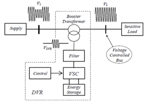
Figure 3. DVR schematic
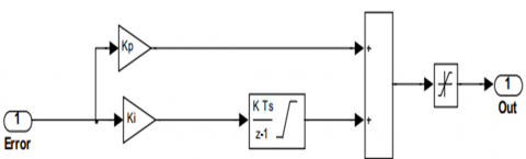
DVR schematic is shown in Figure 3. If the DVR can be controlled or run, this step is not necessary. The linear load voltage is detected and transmitted by a sequence analyzer. This transformation can remove zero sequence components from abc components. The PI controllers with d- and q-coordinates are distinct from one another [17, 18]. Figure 4 depicts a PI controller that regulates the overall error as well as the integral value. As illustrated in Figure 4, the PI controller is a feedback controller that regulates the overall error as well as the integral value.
Figure 4. Show the structure of PI controller
The compensating computer is controlled by a multi-layer back propagation in ANN [19]. The toolbox trains ANNs [20]. The Levenberg Marquardt (LM) Back propagation algorithm [21] supervises the ANN controller. The first order optimization algorithm uses Gradient Descent GD method to find a local minimum function. Despite starting just below the final minimum, this method has poor final convergence. Interpolating between GD and the Gauss Newton (GN) algorithm [22]. Although it starts far from the end goal, the LM algorithm seeks a solution. When compared to the GN algorithm, the LM algorithm has superior training procedures. This algorithm's benefits include faster convergence, less memory usage, and learning. All values for training the ANN come from PI controllers. The ANN controller has three layer one is input 2nd is hidden and 3rd is output. This feedback is the error signals shift, which is the difference between the real and estimated values. The ANN controller reduces errors. The mean square error in the ANN controller's output function represents the input and output values.
Extreme train periods, time, or result minimization are all ways to reject ANN preparation (mu).
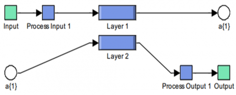
The controller is primarily interested in quickly detecting the disruptive signal with extreme accuracy and a high interactive response to the desired DVR compensation. Under conditions of parameter change, disturbance in the load and non-linearity, etc., the traditional controller cannot operate correctly. A recent survey has shown that an ANN-based controller provides rapid dynamic responses while keeping the DVR stable over a wide range of operating conditions. Moreover, the ANN contains nonlinear elements referred as neurons which are interconnected. It generally represents a cluster of interconnected simple nonlinear elements that have the capacity to learn and adapt. The main blocks of neural networks are shown in Figure 5.
Figure 5. ANN controller
A control system based on the multi-layer neural network is developed to maximize the DVR's performance characteristics. The ANN-based controller has three-layer components, one neuron input layer, 20 neurons hidden layer and one neuron output layer. In the MATLAB workspace, the data obtained from the PI controller are stored which is used for the neural network controller offline training. Here, that activation function used is Train LM for input layer and hidden layers and pure linear for the output layer. Levenberg Marquardt back propagation (LMBP) is the used training algorithm in this study.
Because of the voltage sag and swell of the JDW-II sugar mills 11kV feeder, power quality is an issue, as is unbalanced load distribution in power distribution network. Increased penetration of their load distribution in the existing power system create significant technical challenges. The work improved power quality by employing an artificial neural network (ANN)-based DVR and obtained the highest output from the hybrid system. The key bulletins of the paper are:
Developed simulation model of JDW-II Sugar mills 11kV feeder at MATLAB/Simulink. Developed /designed the model of ANN based DVR controller Integration of proposed designed of DVR in the developed model on MATLAB of JDW-II sugar mills 11kV feeder. Testing of proposed DVR by creating short circuit or any abnormal conditioned on developed model of JDW-II sugar mills 11kV feeder and a comparison between proposed and traditional controller (PI Controller).
For controlling of a synchronized reference frame (dq-control), Park Transformation turns three-phase time-changing signals into DC signals by rotating a frame in time with the voltage vector on the grid. It has dq=1, q=0, and wt=0. It is 90 degrees off of the phase a line.
Transform direct time-domain components to revolving, abc, abc quadrature, and zero. It can keep the active and reactive power by using an invariant Park transform in the abc power frame. In a well-balanced scheme, the whole equals the parts.
The system's three-phase orientation can be specified to match the a-phase to the axis of either the rotating frame at time t=0 or Q. Figure 5 depicts the orientation of the rotor's windings in a stator and a non-rotating dq frame, respectively.
When a four-wire system consisting of phases A, B, C, and neutral was added to it. It calculates the instantaneous power components of the p-q using the formulas provided.
$\left[\begin{array}{l}v_0 \\ v_\alpha \\ v_\beta\end{array}\right]=\sqrt{\frac{2}{3}} \cdot\left[\begin{array}{ccc}1 / \sqrt{2} & 1 / \sqrt{2} & 1 / \sqrt{2} \\ 1 & -1 / 2 & -1 / 2 \\ 0 & \sqrt{3} / 2 & -\sqrt{3} / 2\end{array}\right] \cdot\left[\begin{array}{c}v_a \\ v_b \\ v_c\end{array}\right]$,
$\left[\begin{array}{c}i_0 \\ i_\alpha \\ i_\beta\end{array}\right]=\sqrt{\frac{2}{3}} \cdot\left[\begin{array}{ccc}1 / \sqrt{2} & 1 / \sqrt{2} & 1 / \sqrt{2} \\ 1 & -1 / 2 & -1 / 2 \\ 0 & \sqrt{3} / 2 & -\sqrt{3} / 2\end{array}\right] \cdot\left[\begin{array}{c}i_a \\ i_b \\ i_c\end{array}\right]$
P and Q are related to the same — voltages and currents and can be written as a single unit: P and Q;
$\left[\begin{array}{l}p \\ q\end{array}\right]=\left[\begin{array}{cc}v_\alpha & v_\beta \\ -v_\beta & v_\alpha\end{array}\right] \cdot\left[\begin{array}{l}i_\alpha \\ i_\beta\end{array}\right]$
$P_0=v_0 . i_0$ Instantaneous zero sequence power
$\mathrm{P}=v_\alpha \cdot i_\alpha+v_\beta \cdot i_\beta$ Instantaneous real power
$\mathrm{q}=v_\alpha \cdot i_\beta-v_\beta \cdot i_\alpha$ Instantaneous imaginary power (by definition)
Figure 6. Research overview
They are illustrated in Figure 6 for an electrical system represented in a-b-c coordinates and have the following physical meanings in terms of physical quantities.
3.1 Park transformation
$\left[\begin{array}{l}V_d \\ V_q\end{array}\right]=\frac{2}{3}\left[\begin{array}{lll}\cos \theta & \cos \left(\theta-\frac{2 \pi}{3}\right) & \cos \left(\theta+\frac{2 \pi}{3}\right) \\ \sin \theta & \sin \left(\theta-\frac{2 \pi}{3}\right) & \sin \left(\theta+\frac{2 \pi}{3}\right)\end{array}\right]\left[\begin{array}{l}V_A \\ V_B \\ V_C\end{array}\right]$
$v_{d=} \frac{2}{3}\left(v_a \sin (\theta)+v_b \sin \left(\theta-\frac{2 \pi}{3}\right)+v_c \sin \left(\theta+\frac{2 \pi}{3}\right)\right)$ (5)
$v_{q=} \frac{2}{3}\left(v_a \cos (\theta)+v_b \cos \left(\theta-\frac{2 \pi}{3}\right)+v_c \cos \left(\theta+\frac{2 \pi}{3}\right)\right)$ (6)
$v_0=\frac{1}{3}\left(v_a+v_b+v_c\right)$ (7)
These equations define the conversion from the three-phase system (a, b, c) to the dq0 stationary frame. In this transformation, phase A is oriented to align with the d-axis, which is orthogonal to the q-axis. The angle θ denotes the angular difference between phase A and the d-axis.
3.2 Inverse Park transformation
Proposed DVR model, block diagram and schematic diagram of DVR is illustrated in Figures 7, 8 and 9 of proposed DVR controller based on ANN.
$\left[\begin{array}{l}V_A \\ V_B \\ V_C\end{array}\right]=\left[\begin{array}{cc}\cos \theta & -\sin \theta \\ \cos \left(\theta-\frac{2 \pi}{3}\right) & \sin \left(\theta-\frac{2 \pi}{3}\right) \\ \cos \left(\theta+\frac{2 \pi}{3}\right) & \sin \left(\theta+\frac{2 \pi}{3}\right)\end{array}\right]\left[\begin{array}{l}V_d \\ V_q\end{array}\right]$
$\begin{gathered}\mathrm{V}_{\mathrm{A}}=\mathrm{V}_{\mathrm{d}} \cos \theta-\mathrm{V}_{\mathrm{q}} \sin \theta \\ \mathrm{V}_{\mathrm{B}}=\mathrm{V}_{\mathrm{d}} \cos \left(\theta-\frac{2 \pi}{3}\right)+\mathrm{V}_{\mathrm{q}} \sin \left(\theta-\frac{2 \pi}{3}\right) \\ \mathrm{V}_{\mathrm{c}}=\mathrm{V}_{\mathrm{d}} \cos \left(\theta+\frac{2 \pi}{3}\right)+\mathrm{V}_{\mathrm{q}} \sin \left(\theta+\frac{2 \pi}{3}\right)\end{gathered}$
B. Component used for developed DVR
BUS -3 VI measurement
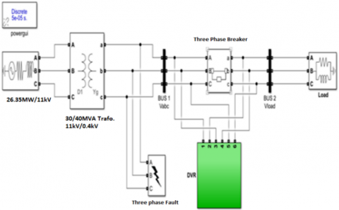
Figure 7. Proposed DVR model
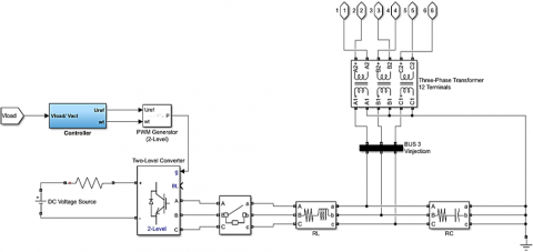
Figure 8. Block diagram of DVR
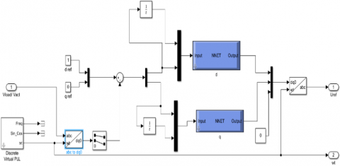
Figure 9. Schematic diagram of proposed DVR controller based on ANN
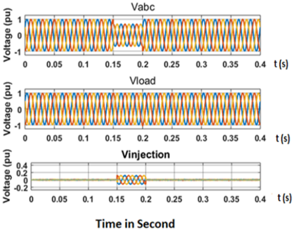
Three-phase voltage sag during fault condition PI controller Injected Voltage is shown in Figure 10.
Three-phase grid & load voltages sag by 60%. Between 0.03 and 0.07 seconds, and duration of 0.04 seconds, and with DVR set to bypass, no voltage is injected.
Figure 10. Shows time on the X-axis and voltage on the Y-axis (PU)
Figure 11. Three phase voltage sag during fault condition
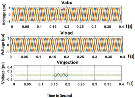
Figure 12. Three-phase voltage swell during fault condition, voltage is injected with DVR, the PI controller is connected with DVR, and the results are under voltage swell conditions
PI controller injected the voltage during fault conditioned. Three-phase voltage swell during fault condition with PI controller is shown in Figure 11.
Three-phase voltage swell under fault-condition condition with ANN controller is shown in Figure 12.
Figure 13. Three-phase supply voltages sag (45 percent)
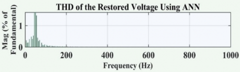
Figure 14. THD of the restored voltage using ANN
Figure 15. Voltage restoration using PI controller
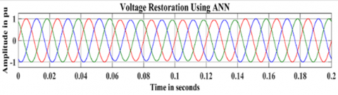
Figure 16. Voltage restoration using ANN controller
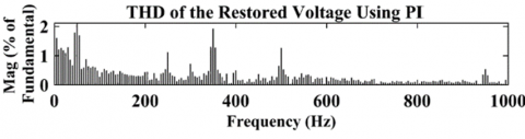
Figure 17. THD of the restored voltage using PI controller
Comparative study ANN versus PI controller is shown in Figure 13. Between 0.03 sec and 0.07 sec of duration 0.04 sec & DVR has injected voltage with controller PI and ANN, the controller response ANN is faster than PI. Total harmonics distortion of the restored voltage using ANN is depicted in Figure 14.
Load voltage under LLLG fault & results are with ANN & PI controller as shown in Figures 15 and 16.
Figure 17 shows the frequency in Hz on the X-axis and THD amplitude on the Y-axis when three-phase supply voltages sag & DVR is injected voltage results are with PI controller. The comparison results of ANN with PI controller are as shown in Table 1.
Table 1. Comparison results of ANN with PI controller
|
Controller |
3- ϕ Sag Voltage Restoration |
1- ϕ Sag Voltage Restoration |
3- ϕ Swell Voltage Restoration |
1- ϕ Swell Voltage Restoration |
THD % |
|
ANN |
99.80% |
99.50% |
99.60% |
99.80% |
13.50 |
|
PI |
98.10% |
98.40% |
97% |
98.20% |
19.70 |
In conclusion, this paper is focused on improving the voltage profile of JDW sugar mills' Jawar Distribution Feeder in RYK, Pakistan, through the implementation of an Artificial Neural Network (ANN)-based dynamic voltage restorer (DVR). The effectiveness of the ANN controller was compared to that of a traditional Proportional-Integral (PI) controller, with specific emphasis on voltage sag compensation, voltage swell compensation, and Total Harmonic Distortion (THD) reduction. The results obtained from the comparison between the ANN and PI controllers were significant. The ANN controller demonstrated superior performance in various aspects. It achieved a lower THD of 13.5% compared to the PI controller's 19.7%, indicating its capability to effectively mitigate harmonic distortions in the system.
Regarding voltage sag compensation, the ANN controller achieved an impressive restoration rate of 99.8% for 3-phase voltage sags, outperforming the PI controller's restoration rate of 98.1%. Similarly, for 3-phase voltage swells, the ANN controller achieved a restoration rate of 99.6%, surpassing the PI controller's restoration rate of 97%.
For 1-phase voltage swells, the ANN controller achieved a restoration rate of 99.8%, while the PI controller achieved a restoration rate of 98.2%. Moreover, the ANN controller demonstrated excellent performance in 1-phase voltage sag compensation, achieving a restoration rate of 99.5%, compared to the PI controller's restoration rate of 98.4%.
These results clearly indicate that the ANN-based DVR system outperforms the traditional PI controller in terms of voltage sag compensation, voltage swell compensation, and THD reduction. The ANN controller's superior performance can be attributed to its ability to learn from historical data and make accurate predictions, enabling it to respond promptly to voltage variations and restore them to the desired levels.
The findings of this research have significant implications for the power distribution industry, particularly in industrial settings like JDW sugar mills. By effectively compensating for voltage sags, swells, and reducing THD, the proposed ANN-based DVR system ensures a stable and reliable power supply, minimizing equipment damage, downtime, and associated financial losses.
[1] Vanam, S., Bharath, B.S.P. (2022). Power quality improvement in grid system with PV based SVPWM-DVR for sag & swell mitigation with a novel ANN controller. In 2022 International Conference on Electronic Systems and Intelligent Computing (ICESIC), Chennai, India, pp. 200-205. https://doi.org/10.1109/ICESIC53714.2022.9783590
[2] Tata, H., Madeti, S.R.K., Sai Veerraju, M. (2022). Power quality improvement of a hybrid renewable energy systems using dynamic voltage restorer with PI controller. In International Conference on Recent Advances in Mechanical Engineering Research and Development, pp. 549-559. https://doi.org/10.1007/978-981-19-9493-7_53
[3] Reddy, N.V.K., Reddy, R.S., Vikram, S.M., Manitha, P.V., Deepa, K., Sailaja, V. (2022). Voltage Sag compensation with DVR based on machine learning controller. In 2022 International Conference on Applied Artificial Intelligence and Computing (ICAAIC), Salem, India, pp. 508-514. https://doi.org/10.1109/ICAAIC53929.2022.9793314
[4] Dhalayat, A.A.K., Hasabe, R.P. (2022). Dynamic voltage restorer for power quality enhancement with improved efficiency using artificial neural networks. In 2022 2nd International Conference on Intelligent Technologies (CONIT), Hubli, India, pp. 1-7. https://doi.org/10.1109/CONIT55038.2022.9848191
[5] Abas, N., Dilshad, S., Khalid, A., Saleem, M.S., Khan, N. (2020). Power quality improvement using dynamic voltage restorer. IEEE Access, 8: 164325-164339. https://doi.org/10.1109/ACCESS.2020.3022477
[6] Lavanya, V., Kumar, N.S. (2018). A review: Control strategies for power quality improvement in microgrid. International Journal of Renewable Energy Research, 8(1): 1-16.
[7] Raptis, T.E., Vokas, G.A., Langouranis, P.A., Kaminaris, S.D. (2015). Total power quality index for electrical networks using neural networks. Energy Procedia, 74: 1499-1507. https://doi.org/10.1016/j.egypro.2015.07.706
[8] Mostefa, T., Tarak, B., Hachemi, G. (2018). An automatic diagnosis method for an open switch fault in unified power quality conditioner based on artificial neural network. Traitement du Signal, 35(1): 7-21. https://doi.org/10.3166/TS.35.7-21
[9] Islam, F.R., Lallu, A., Mamun, K.A., Prakash, K., Roy, N.K. (2020). Power quality improvement of distribution network using BESS and capacitor bank. Journal of Modern Power Systems and Clean Energy, 9(3): 625-632. https://doi.org/10.15662/IJAREEIE.2017.0605034
[10] Shuai, Z., Yao, P., Shen, Z.J., Tu, C., Jiang, F., Cheng, Y. (2014). Design considerations of a fault current limiting dynamic voltage restorer (FCL-DVR). IEEE Transactions on Smart Grid, 6(1): 14-25. https://doi.org/10.1109/TSG.2014.2357260
[11] Pal, R., Gupta, S. (2015). State of the art: Dynamic voltage restorer for power quality improvement. Electrical & Computer Engineering: An International Journal (ECIJ), 4(2), 79-98. https://doi.org/10.14810/ecij.2015.4208
[12] Natesan, C., Ajithan, S.K., Palani, P., Kandhasamy, P. (2014). Survey on microgrid: Power quality improvement techniques. International Scholarly Research Notices, 2014: Article ID 342019. http://doi.org/10.1155/2014/342019
[13] Zheng, Z., Xiao, X., Huang, C., Li, C. (2018). Enhancing transient voltage quality in a distribution power system with SMES-based DVR and SFCL. IEEE Transactions on Applied Superconductivity, 29(2): 1-5. https://doi.org/10.1109/TASC.2018.2882469
[14] Son, J., Hussain, R., Kim, H., Oh, H. (2014). SC-DVR: A secure cloud computing based framework for DVR service. IEEE Transactions on Consumer Electronics, 60(3): 368-374. https://doi.org/10.1109/TCE.2014.6937320
[15] Pradhan, M., Mishra, M.K. (2018). Dual P-Q theory based energy-optimized dynamic voltage restorer for power quality improvement in a distribution system. IEEE Transactions on Industrial Electronics, 66(4): 2946-2955. https://doi.org/10.1109/TIE.2018.2850009
[16] Srilakshmi, B., Reddy, K.S., Mahadeva, H.C., Gayathri, M. (2018). Power quality improvement using dynamic voltage restorer. In 2018 3rd IEEE International Conference on Recent Trends in Electronics, Information & Communication Technology (RTEICT), Bangalore, India, pp. 558-561. https://doi.org/1109/RTEICT42901.2018.9012583
[17] Pal, K., Akella, A.K., Namrata, K., Pati, S. (2022). Classification of fault using artificial neural network and power quality improvement using DVR in a PV integrated hybrid power system. In 2022 International Conference on Intelligent Controller and Computing for Smart Power (ICICCSP), Hyderabad, India, pp. 1-4. https://doi.org/10.1109/ICICCSP53532.2022.9862499
[18] Farhat, M., Hussein, M., Atallah, A.M. (2017). Enhancement performance of a three phase grid connected photovoltaic system based on pi-genetic algorithm (PI-GA) controller. In 2017 Nineteenth International Middle East Power Systems Conference (MEPCON), Cairo, Egypt, pp. 145-151. https://doi.org/10.1109/MEPCON.2017.8301177
[19] Sulehri, A.M., Jeelani, N., Ikram, A.A. (2018). Power quality improvement in an AC network using artificial neural network and hysteresis band current controller. Ingeniería e Investigación, 38(3): 42-49. https://doi.org/10.15446/ing.investig.v38n3.67885
[20] Kumar, T.A., Rao, L.S. (2017). Improvement of power quality of distribution system using ANN-LMBNN based D-STATCOM. In 2017 Innovations in Power and Advanced Computing Technologies (i-PACT), Vellore, India, pp. 1-6. https://doi.org/10.1109/IPACT.2017.8245211
[21] Chauhan, A., Goswami, A. (2018). Power quality improvement by DSTATCOM control by artificial neural network technique. International Research Journal of Engineering and Technology (IRJET), 5(12): pp. 1397-1399.
[22] Ab-BelKhair, A., Rahebi, J., Nureddin, A.A.M. (2020). A study of deep neural network controller-based power quality improvement of hybrid PV/Wind systems by using smart inverter. International Journal of Photoenergy, Article ID 8891469. https://doi.org/10.1155/2020/8891469