Elaf J. Dhulkefl![]() | Zuhair Shakor Mahmood*
| Zuhair Shakor Mahmood*![]() | Ali Najdet Nasret
| Ali Najdet Nasret![]() | Ahmed Burhan Mohammed
| Ahmed Burhan Mohammed![]()
© 2023 IIETA. This article is published by IIETA and is licensed under the CC BY 4.0 license (http://creativecommons.org/licenses/by/4.0/).
OPEN ACCESS
The integration of sensor fusion techniques has played a crucial role in the advancement of the contemporary robot applications era. This is primarily due to the fact that numerous robot applications heavily rely on the amalgamation of data from multiple sensors, which capture information from the immediate surroundings. Examples of such applications include interactive virtual reality games, navigation systems, and fitness trackers. This study presents the implementation of a sensor fusion technique utilizing low-cost sensors, specifically a gyro sensor and a tilt sensor, to precisely estimate the balancing angle of an inverted pendulum robot system. Hence, this research study presents an innovative approach to address the issue of gyro drift, which has a detrimental impact on the precision of orientation calculations in the indirect Kalman filter-based sensor fusion. The emergence of kinematics and dynamics is observed in this particular process. The frequency responses of two distinct sensors, namely a gyro and a tilt sensor, have been subjected to analysis. A technique of sensor fusion has been utilized to counterbalance the inherent drift of the gyroscope sensor. The integration of a low-cost gyro sensor and a tilt sensor through the process of filtering facilitates the determination of the pendulum angle with efficacy, thereby eliminating the necessity of deploying more expensive sensors. The implementation of control for tracking circular trajectories has been carried out in empirical investigations.
gyroscope sensor, gyro sensor, mobile inverted pendulum
As an extension of the classic inverted pendulum system, the mobile inverted pendulum system is seen as a potentially fruitful field of research. Due of its exceptional mobility, the inverted pendulum system on wheels has garnered considerable interest. The device in question showcases a combination design that combines elements of a wheeled mobile robot with an inverted pendulum [1].
The renowned Segway has invented a novel mobility system based on an inverted pendulum, which has some intriguing properties. Commercialized for human use, the Segway is a standard movable pendulum transit device. Unfortunately, the Segway technology is beyond of reach for most people since it requires high-priced sensors for control [2].
Numerous studies on the subject of controlling an inverted pendulum with two wheels have been carried out. The JOE is a portable inverted pendulum device that is quite tiny. The mobile pendulum system aims to achieve two control goals: balance and navigation. As it navigates its terrain, the system must remain stable.
The mobile pendulum system has had disturbance observer-based control implemented in order to regulate its behaviour. Control based on the use of partial feedback linearization has been provided.
The precise determination of the angle of the mobile pendulum system and the position of the cart is of utmost importance for the effective regulation of the mobile pendulum system. Encoder sensors exhibit higher reliability compared to gyro sensors, with the latter's performance being directly proportional to their cost [3, 4].
Consequently, the present study details the construction of a novel mobile pendulum robot with a focus on optimizing cost-effectiveness. The measurement of the pendulum's angle is achieved by means of a cost-effective gyro sensor and tilt sensor. The lower-cost gyro sensor manifests temporal drift as a consequence of the integration process that is entailed in the acquisition of angle measurements. The presence of gyro sensor drift poses a challenge to the usability of measurement data by controllers, as it causes deviations in the data. Prior to implementing control measures on the mobile pendulum system, it is imperative to ensure accurate data acquisition. Otherwise, the assurance of control performance cannot be guaranteed [5, 6].
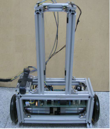
The proposed methodology entails the utilization of a dual-sensor system to estimate the angular velocity of the pendulum. Although both the gyro and tilt sensors are capable of detecting an object's inclination in relation to the ground, the gyro's superior high frequency response renders it a more optimal selection. The integration of multiple sensors enhances the precision of the angular velocity computation of the pendulum. Two domains that have been actively researched to tackle the drift problem of gyro sensors are the development of filters and the modelling of the sensor using neural networks [7, 8]. Presently, the mobile applications era is anticipating the forthcoming generation in which a virtual personal assistant (VPA) assumes the role of a central unified framework. This framework integrates distinct applications to provide individuals contextually aware individualized information and services. Sensor fusion is a crucial component in enhancing the precision of multi-sensing information derived from the surrounding environment, thereby facilitating accurate responses from virtual personal assistants (VPAs) to user requests. Additionally, sensor fusion contributes to the development of user experience features for interactive relaxation applications and other related purposes. This is achieved through the collaborative integration of diverse advanced technologies . .Through the utilization of the Internet of Things (IoT) infrastructure, it becomes possible to establish interconnections with a diverse array of sensors. In the context of human activities of daily life (HADL), the accelerometer and gyroscope sensors are widely utilized and have become ubiquitous in modern smartphones. Furthermore, it is projected that this advancement will last for a minimum of the following ten years [9, 10]. The Figure 1 shows the inverted pendulum on two wheels while the Figure 2 represent the portable of pendulum.
Figure 1. Inverted pendulum on two wheels
Nevertheless, the swift advancements in smartphone technology have posed challenges for mobile applications since they necessitate code modifications to accommodate the integration of supplementary hardware components in newer devices [11, 12]. This issue has a detrimental impact on a significant number of smartphones currently in use worldwide, as well as a substantial quantity of programs available in various marketplaces. The pedometer sensor was incorporated into the Google Nexus 5 (Google, San Francisco, CA, USA), Samsung Galaxy S5 (Samsung, Seoul, Korea), and Apple iPhone 5S (Apple, Cupertino, CA, USA) iterations, as exemplified. Hence, the step-count data provided by the pedometer cannot be considered without making adjustments to its underlying code. Furthermore, in the event that developers attempt to modify and recompile the code in order to incorporate the sensor fusion technique for enhancing their apps, an additional issue develops as the applications independently employ sensor fusion utilizing their own distinct methodologies. The aforementioned issue not only imposes a strain on the operational efficiency of the smartphone, but also introduces additional delays in the processing duration.
The determination of the pendulum's angle is accomplished through the utilization of a gyro sensor and tilt sensor that are economically efficient. The integration process involved in acquiring angle measurements with the lower-cost gyro sensor results in temporal drift [13, 14].
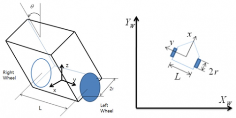
Figure 2. Portable inverted pendulum
The robot is characterized using the following equations for its linear velocity $v_m$ and its orientation angular velocity $\omega_m$:
${{\omega }_{m}}=\frac{{{v}_{R}}-{{v}_{L}}}{L}$ (1)
${{v}_{m}}=\frac{{{v}_{R}}+{{v}_{L}}}{2}$ (2)
${{\omega }_{m}}={{\phi }_{m}}$ (3)
The equation's variables are designated as such: r represents the wheel's radius, L represents the distance between the wheels, and $\phi _m$ represents the orientation angle.
The determination of the velocity for each axis, namely x and y, in the mobile inverted pendulum system can be expressed in the subsequent manner.
Velocity along the x-axis $v_m$:
${{v}_{x}}={{v}_{m}}*\cos \left( {{\phi }_{m}} \right)$ (4)
Velocity along the y-axis $v_y$:
${{v}_{y}}={{v}_{m}}*\sin \left( {{\phi }_{m}} \right)$ (5)
where, $v_m$ is the linear velocity of the robot, and $\phi _m$ is the orientation angle of the robot.
These equations describe how the overall linear velocity of the robot $v_m$ is decomposed into its x and y components based on the orientation angle $\phi _m$. The horizontal velocity of the robot is denoted by the x-velocity ($v_x$), whereas the vertical velocity of the robot is represented by the y-velocity $v_y$.
$\left[ \begin{matrix} {{v}_{x}} \\ {{v}_{y}} \\ {{\phi }_{m}} \\ \end{matrix} \right]=\left[ \begin{matrix} \cos {{\phi }_{m}} & 0 \\ \sin {{\phi }_{m}} & 0 \\ 0 & 0 \\ \end{matrix} \right]=\left[ \begin{matrix} {{v}_{m}} \\ {{\omega }_{m}} \\ \end{matrix} \right]$ (6)
$\left[ \begin{matrix} {{v}_{m}} \\ {{\omega }_{m}} \\ \end{matrix} \right]=\left[ \begin{matrix} \frac{r}{2} & \frac{r}{2} \\ \frac{r}{L} & -\frac{r}{L} \\ \end{matrix} \right]\left[ \begin{matrix} {{\omega }_{R}} \\ {{\omega }_{L}} \\ \end{matrix} \right]$ (7)
Combining Eqs. (6) and (7), we can derive the kinematics matrix for the mobile inverted pendulum system as follows:
$\left[ \begin{matrix} {\dot{x}} \\ {\dot{y}} \\ {{{\dot{\phi }}}_{m}} \\ \end{matrix} \right]=\left[ \begin{matrix} \frac{r}{2}\cos {{\phi }_{m}} & \frac{r}{2}\cos {{\phi }_{m}} \\ \frac{r}{2}\sin {{\phi }_{m}} & \frac{r}{2}\sin {{\phi }_{m}} \\ \frac{r}{L} & -\frac{r}{L} \\ \end{matrix} \right]\left[ \begin{matrix} {{\omega }_{R}} \\ {{\omega }_{L}} \\ \end{matrix} \right]$ (8)
It is noteworthy that the MIPS exhibits non-holonomic characteristics and possesses a restricted set of kinematic equations. The subsequent text presents a depiction of the motion equation pertaining to the mobile robot with wheeled drive, which is subject to kinematics constraints.
$M\left( q \right)\ddot{q}+C\left( q\cdot \dot{q} \right)+{{A}^{T}}\lambda =p\tau $ (9)
where:
Considering the inertia, Coriolis/centrifugal forces, restrictions, and input torques, this equation summarizes the MIPS's entire dynamics. You may get the accelerations of the system by solving this equation. $\ddot{q}$, and hence the prediction of its motion and behavior over time [8].
The symbols present in the given equation are explicitly defined as follows: The symbols M(q), $C(q \cdot \dot{q})$, A, P, u, and λ respectively represent the inertia matrix, Coriolis and centrifugal force vector, constraint matrix, input transform matrix, input torque vector, and Lagrangian multiplier [9-16].
$\dot{q}=S\left( q \right)v$ (10)
$S\left( q \right)=\left[ \begin{matrix} \cos \phi & 0 & 0 \\ \sin \phi & 0 & 0 \\ 0 & 1 & 0 \\ 0 & 0 & 1 \\ \frac{1}{r} & \frac{L}{2r} & 0 \\ \frac{1}{r} & -\frac{L}{2r} & 0 \\ \end{matrix} \right]$ (11)
When the constraint A(q) matrix is found to be supplied by the kinematic constraint equations.
$A\left( q \right)=\left[ \begin{matrix} \sin \phi & -\cos \phi & 0 & 0 & 0 & 0 \\ \cos \phi & \sin \phi & \frac{L}{2} & 0 & -r & 0 \\ \cos \phi & \sin \phi & -\frac{L}{2} & 0 & 0 & -r \\ \end{matrix} \right]$ (12)
The acceleration is obtained by differentiating (10), then plugging that result into Eq. (9).
$\ddot{q}=\dot{S}v+S\dot{v}$ (13)
When the gravity factor is taken into account and (13) is substituted into (9), we get
$MS\dot{v}+M\dot{S}v+C+G=P\tau -{{A}^{T}}\lambda $ (14)
${{S}^{T}}MS\dot{v}+{{S}^{T}}M\dot{S}v+{{S}^{T}}\left( C+G \right)={{S}^{T}}P\tau $ (15)
4.1 Sensing devices' frequency responses
Frequency response testing has been performed on all sensors to determine their individual qualities. In order to test sensors, a special board has been developed. On the spinning link, you'll find gyro and tilt sensors for checking the reaction at various frequencies.
Each filter's frequency response is measured and shown in Figure 3. Zero hertz to six hertz is the frequency range. Comparing the gyro sensor with the tilt sensor, we find that the former can be described as the first order system, but the latter cannot. In contrast to the gyro sensor, the tilt sensor has an unexpected response at frequencies around 2 Hz, making it impossible to model accurately. Since the gyro sensor works well at high frequencies, it may be used in conjunction with the tilt sensor, which works well at low frequencies. The complementary filter is the result [15, 16].
${{H}_{t}}\left( s \right){{F}_{t}}\left( s \right)+{{H}_{g}}\left( s \right){{F}_{g}}\left( s \right)=1$ (16)
where, $H_t(s)=1, H_g(s)=1, F_t(s)=\frac{1}{\tau s+1}$.
${{F}_{t}}\left( s \right)=\frac{\tau s}{\tau s+1}$
The tilt is subjected to a filter with a low pass characteristic, whereas the gyro is subjected to a filter with a high pass characteristic. The parameter τ has been determined through empirical observation and has been designated a numerical value of 0.5.
The diagram is depicted in Figure 4, which demonstrates a methodology for sensor fusion that is based on filtering. The signals generated by each sensor are subjected to filtration using the complementary filter. The resulting outputs are then aggregated through the process of summation. The estimation of the angle of the pendulum is subsequently performed by employing the Kalman filter [17, 18].
Figure 3. Each sensor's frequency response was studied in detail
Figure 4. The diagram depicting the process of filtering sensors
4.2 The process of refining or screening outcomes to obtain a more specific and relevant set of data
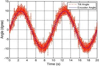
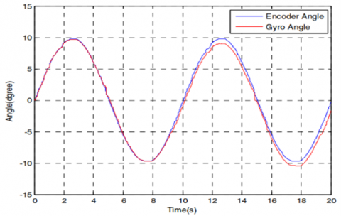
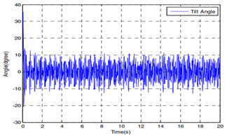
The effectiveness of the filter has been assessed at different frequencies. The sensor's output at a frequency of 0.3 Hz is illustrated in Figures 5, 6, and 7. The obtained outcomes are juxtaposed with the data obtained from an encoder sensor. Figures 8, 9, and 10 depict the 2.5 Hz movements subsequent to the application of the complementary filter and the Kalman filter. The diagram presented in Figure 8 illustrates the results obtained from the tilt sensor, revealing a significant level of noise in the output. Figure 9 portrays the drift of the gyro signal, whereas Figure 10 demonstrates the filtering process that has been implemented on these signals. Whilst the readings produced by the encoder and gyro sensor may bear similarities, it is important to note that the latter is susceptible to the issue of drift.
Figure 5. The angle of tilt at a frequency of 0.3 Hz
Figure 6. Angular displacement of a gyroscope at a frequency of 0.3 Hz
Figure 7. The filtered angle at a frequency of 0.3 Hz
Figure 8. The angle of inclination at a frequency of 2.5 Hz
Figure 9. The angular orientation of a gyro at a frequency of 2.5 Hz
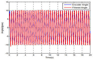
The resolution of the drift problem is accomplished via signal filtration, as illustrated in Figure 10 that exhibits the resultant filtered signals. The signals captured by the sensors display a noteworthy similarity to the output signals generated by the encoder sensor, which functions as the point of comparison. Therefore, the effectiveness of signal filtration is observed.
Figure 10. The filtered angle at a frequency of 2.5 Hz
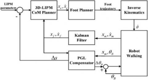
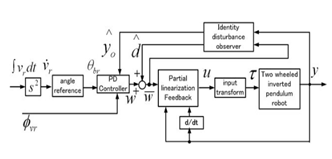
The angle $\theta_d$ and angular velocity $\dot{\theta}_d$ are both set to zero as per the prescribed values. The PD controller has been purposefully developed to govern the heading angle denoted as $\emptyset_{m d}$. The studies conducted involved the implementation of a Proportional-Derivative (PD) control system with feedforward compensation on a robotic platform. The study revealed that the tracking errors, denoted as ˜q, exhibited a decrease when an increased number of feedforward terms were taken into account. The experimental results were reported utilizing two model-based methods, specifically the PD control with feedforward compensation and the computed torque control. The researchers reached the conclusion that both control methods exhibited equivalent performance and demonstrated a considerable enhancement in tracking accuracy, in comparison to the independent joint PD control. The PID controller is utilized to regulate the position of the system. The mathematical expressions dictating the rotational force exerted by the left and right wheels are delineated. The PID controller ensures system stability by maintaining a consistent error range, while the feedforward learning scheme adapts to and counteracts the nonlinear dynamics of an uncertain robotic system [19]. However, throughout the learning process, it is necessary to set the fixed PID gains at a reasonably big value in order to ensure the stability of the overall learning system, as indicated by the following statement. Figure 11 illustrates the block diagram of controlling.
$\begin{align} & {{\tau }_{L}}={{K}_{1}}\left( {{\theta }_{d}}-\theta \right)+{{K}_{2}}\left( {{{\dot{\theta }}}_{d}}-\dot{\theta } \right)+{{K}_{3}}\left( {{\phi }_{md}} \right)+ \\ & {{K}_{4}}\left( {{\omega }_{md}}-{{\omega }_{m}} \right)+{{K}_{5}}\left( {{x}_{md}}-{{x}_{m}} \right)+{{K}_{6}}\left( {{v}_{md}}-{{v}_{m}} \right) \\ & +{{K}_{7}}\int\limits_{0}^{1}{\left( {{x}_{md}}-{{x}_{m}} \right)dt} \\ \end{align}$ (16)
$\begin{align} & {{\tau }_{R}}={{K}_{1}}\left( {{\theta }_{d}}-\theta \right)+{{K}_{2}}\left( {{{\dot{\theta }}}_{d}}-\dot{\theta } \right)-{{K}_{3}}\left( {{\phi }_{md}} \right)- \\ & {{K}_{4}}\left( {{\omega }_{md}}-{{\omega }_{m}} \right)+{{K}_{5}}\left( {{x}_{md}}-{{x}_{m}} \right)+{{K}_{6}}\left( {{v}_{md}}-{{v}_{m}} \right) \\ & +{{K}_{7}}\int\limits_{0}^{1}{\left( {{x}_{md}}-{{x}_{m}} \right)dt} \\ \end{align}$ (17)
Figure 11. Block diagram for controlling
6.1 The results derived from empirical research conducted through scientific inquiry
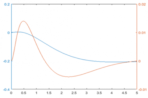
Figure 12. The angle of the body refers to the position or orientation of the body in relation to a reference point or axis
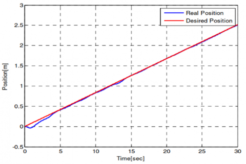
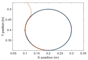
The pursuit of a circular trajectory is a necessary condition for the mobile pendulum robot. It took 30 seconds to complete one revolution around the circular path with a diameter of 0.8 meters. The diagram presented in Figure 12 illustrates the angular displacement of the pendulum. The robotic system is capable of maintaining equilibrium with a high degree of effectiveness, even in the presence of an angular error of approximately 0.02 radians. The figures depicting the results of tracking are presented as Figures 13, 14, and 15. The outcome of the circular trajectory tracking exhibits a minor deviation attributed to the process of dead reckoning.
Figure 13. Position
Figure 14. Direction
Figure 15. The outcome of circular trajectory tracking
The present study outlines a methodology for assessing the efficacy of low-cost sensors, namely the gyro and tilt sensor, for the purpose of detecting the angle of a pendulum. The accurate measurement of angles is made easier through the application of both the complementary filter and the Kalman filter. The utilization of basic PID controllers is employed to regulate the trajectory tracking of the robot while concurrently ensuring balance. Notwithstanding the effective demonstration evinced by empirical studies, there exists a tracking error. The proposal suggests exploring the potential field of study that involves the advancement of intricate control algorithms with the objective of reducing tracking errors. The incorporation of dual appendages onto the mobile inverted pendulum platform will facilitate not only locomotion but also the accomplishment of diverse objectives. The empirical findings indicate that our proposed approach has superior performance and accuracy. Furthermore, it should be noted that any modifications made to the device driver do not have a detrimental impact on the upper-level programs. The applications are not required to make any changes to their code or undergo the process of re-programming and re-compiling in order to make use of the sensor fusion capabilities. In future investigations, the suggested framework will be extended to facilitate interaction with additional sensors and will be deployed to accommodate diverse hardware and operating systems of various devices.
[1] Israilov, S., Fu, L., Sánchez-Rodríguez, J., Fusco, F., Allibert, G., Raufaste, C., Argentina, M. (2023). Reinforcement learning approach to control an inverted pendulum: A general framework for educational purposes. Plos One, 18(2): e0280071. https://doi.org/10.1371/journal.pone.0280071
[2] Feng, Z., Li, R.B., Wu, L. (2023). Adaptive decentralized control for constrained strong interconnected nonlinear systems and its application to inverted pendulum. IEEE Transactions on Neural Networks and Learning Systems. https://doi.org/10.1109/TNNLS.2023.3238819
[3] Hofer, M., Muehlebach, M., D’Andrea, R. (2023). The One-Wheel Cubli: A 3D inverted pendulum that can balance with a single reaction wheel. Mechatronics, 91: 102965. https://doi.org/10.1016/j.mechatronics.2023.102965
[4] Zhang, B., Guo, H., Ding, J., Luo, J., Wang, M., Sun, Y., Pu, H. (2023). A quasi-zero adjustable stiffness magnetoelectric generator of an inverted pendulum for ultra-low frequency blue energy harvesting. Nano Energy, 112: 108478. https://doi.org/10.1016/j.nanoen.2023.108478
[5] Zeghlache, S., Ghellab, M.Z., Djerioui, A., Bouderah, B., Benkhoris, M.F. (2023). Adaptive fuzzy fast terminal sliding mode control for inverted pendulum-cart system with actuator faults. Mathematics and Computers in Simulation, 210: 207-234. https://doi.org/10.1016/j.matcom.2023.03.005
[6] Sun, Z., Hu, S., Xie, H., Li, H., Zheng, J., Chen, B. (2023). Fuzzy adaptive recursive terminal sliding mode control for an agricultural omnidirectional mobile robot. Computers and Electrical Engineering, 105: 108529.
[7] Zeghlache, S., Ghellab, M.Z., Djerioui, A., Bouderah, B., Benkhoris, M.F. (2023). Adaptive fuzzy fast terminal sliding mode control for inverted pendulum-cart system with actuator faults. Mathematics and Computers in Simulation, 210: 207-234.
[8] Nagarajan, A., Victoire, A.A. (2023). Optimization reinforced PID-sliding mode controller for rotary inverted pendulum. IEEE Access, 11: 24420-24430. https://doi.org/10.1109/ACCESS.2023.3254591
[9] Oloo, J. (2023). Effect of loss of control effectiveness on an inverted pendulum balanced on a moving quadrotor. Heliyon, 9(3): e14494. https://doi.org/10.1016/j.heliyon.2023.e14494
[10] Catenacci Volpi, N., Greaves, M., Trendafilov, D., Salge, C., Pezzulo, G., Polani, D. (2023). Skilled motor control of an inverted pendulum implies low entropy of states but high entropy of actions. PLoS Computational Biology, 19(1): e1010810. https://doi.org/10.1371/journal.pcbi.1010810
[11] Balogh, T., Insperger, T. (2023). Extending the admissible control-loop delays for the inverted pendulum by fractional-order proportional-derivative controller. Journal of Vibration and Control, 10775463231181662. https://doi.org/10.1177/10775463231181662
[12] Ping, Z., Xu, D., Tang, H., Ge, S., Lu, J.G., Wang, H. (2023). Switched energy and neural network-based approach for swing-up and tracking control of double inverted pendulum. IEEE Transactions on Systems, Man, and Cybernetics: Systems, 53(9): 5536-5544. https://doi.org/10.1109/TSMC.2023.3273820
[13] Bhourji, R.S., Mozaffari, S., Alirezaee, S. (2023). Reinforcement learning DDPG–PPO agent-based control system for rotary inverted pendulum. Arabian Journal for Science and Engineering, 1-14. https://doi.org/10.1007/s13369-023-07934-2
[14] Saleem, O., Abbas, F., Iqbal, J. (2023). Complex fractional-order LQIR for inverted-pendulum-type robotic mechanisms: Design and experimental validation. Mathematics, 11(4): 913. https://doi.org/10.3390/math11040913
[15] de Carvalho Junior, A., Angelico, B.A., Justo, J.F., de Oliveira, A.M., da Silva Filho, J.I. (2023). Model reference control by recurrent neural network built with paraconsistent neurons for trajectory tracking of a rotary inverted pendulum. Applied Soft Computing, 133: 109927. https://doi.org/10.1016/j.asoc.2022.109927
[16] Kowalczyk, P., Płociniczak, Ł., Wróblewska, Z. (2023). Energy variations and periodic solutions in a switched inverted pendulum model of human running gaits. Physica D: Nonlinear Phenomena, 443: 133554. https://doi.org/10.1016/j.physd.2022.133554
[17] Mahmood, Z.S., Nasret, A.N., Mahmood, O.T. (2021). Separately excited DC motor speed using ANN neural network. AIP Conference Proceedings, 2404(1): 080012. https://doi.org/10.1063/5.0068893
[18] Mahmood, Z.S., Kadhim, I.B., Nasret, A.N. (2021). Design of rotary inverted pendulum swinging-up and stabilizing. Periodicals of Engineering and Natural Sciences, 9(4): 913-920. http://dx.doi.org/10.21533/pen.v9i4.2453
[19] Salih, A.B., Mahmood, Z.S., Ali, A.H.M., Nasret, A.N. (2022). Enhancement of motor speed identification using artificial neural networks. Indonesian Journal of Electrical Engineering and Computer Science, 27(3): 1388-1396. https://doi.org/10.11591/ijeecs.v27.i3.pp1388-1396